ABB_ 800xA 创建一个趋势模版
- 格式:pdf
- 大小:402.48 KB
- 文档页数:4

1ABB 800xA 系统画面编辑之菜单栏1. 新增菜单栏第一层 第二层 第三层新增第三层2在新增层数添加画面:添加的画面编辑:需要注意的是,此处每一层的名字都有其含义,在接下来的画面编辑会用到;如上文,一共7大层,每一个大层包括N 个中层,中层又包括N 个小层,最终的画面是在小层上添加的;上文是在A7-Test 大层添加了中层G1-Layer1,再添加小层011-Layer1,最后在小层添加画面test1,三层名字在下文的函数编辑都需要对应。
编辑简单的按钮及文本32. 菜单栏设计2.1 整体框架设计2.2 添加元素123后面依次类推第一层 第二层第三层42.2 添加元素5这些元素的属性包含了很多变量及函数,接下来会逐一介绍。
注5注6672.3 输入属性及变量的添加2.3.1图为添加的变量82.3.2 属性的添加图为添加的输入属性2.4 变量及属性定义变量1:EV_TabRowSelHeight-------------- EV_Height * 0.28EV_Height ---------------------------_Height 内部变量,见2.3.1变量2:EV_PathArea----------------------------""变量3:EV_NameArea7------------------------String(LateBoundPropertyRef("[Operator Workflow Structure]" + EV_PathSite + "/A7-*", "Name", "Name", True, 0)#Value)变量定义如下:EV_PathSite------------------------------ EV_PathArray#GetValue(0)EV_PathArray ----------------Split(EV_CurrentViewRef#ReferencePresentation(ObjectPath), "/")EV_CurrentViewRef -------CurrentDisplayViewReference()变量4:VisbleArea 输入属性见2.3.2变量5:EV_WidthArea------------------EV_Width / 10.EV_Width-----------------------_Width 同上内部变量变量6:EV_YPosAreaSel------------------ EV_TabRowHeadHeightEV_TabRowHeadHeight -------- EV_TabRowHeight * 0.2EV_TabRowHeight-------------- EV_Height * 0.28变量7:EV_TabRowHeight-----------------见变量6变量8:EV_Area7Sel-----------------------EV_PathArea = EV_NameArea7变量定义如下:EV_NameArea7------------String(LateBoundPropertyRef("[Operator Workflow Structure]" +EV_PathSite + "/A7-*", "Name", "Name", True, 0)#Value)EV_PathArea以及EV_PathSite见变量3变量9:EV_PathGroup-----------------""变量10:EV_NameGroup11-----------String(LateBoundPropertyRef("[Operator Workflow Structure]" + EV_PathSite + "/" + EV_PathArea + "/G1*", "Name", "Name", True, 0)#Value)EV_PathArea以及EV_PathSite见变量39变量11:VisibleGroup-----------同样属于输入属性,见变量4变量12:EV_WidthGroup-------- EV_Width/8变量13:EV_YPosGroupSel------ if VisibleArea then EV_TabRowHeight + EV_TabRowGap + EV_TabRowHeadHeight else EV_TabRowHeadHeight变量定义如下:VisibleArea-------------属于输入属性,见变量4EV_TabRowHeight 以及 EV_TabRowHeadHeight见变量6EV_TabRowGap-----------EV_Height*0.03变量14:EV_Group1Sel------------EV_PathGroup = EV_NameGroup11EV_PathGroup见变量9EV_NameGroup11见变量10变量15:EV_YPosGroup----if VisibleArea then EV_TabRowHeight + EV_TabRowGap else 0.VisibleArea-------------属于输入属性,见变量4EV_TabRowHeight 以及EV_TabRowGap见变量13变量16:EV_DisplayButtonWidth---------EV_Width / NumberOfDisplayButtonsEV_Width-----------------------_Width 同上内部变量NumberOfDisplayButtons------见变量4中输入属性,初始值12变量17:EV_YPosDisplay---------if VisibleArea && VisibleGroup then (EV_TabRowHeight +EV_TabRowGap) * 2 else if VisibleArea || VisibleGroup then EV_TabRowHeight + EV_TabRowGap else 0VisibleArea以及VisibleGroup见变量4中输入属性,初始值trueEV_TabRowHeight 以及EV_TabRowGap见变量1310112.4 函数说明注1 第一层文本显示代码: if IP_TrimEnable then Substring(EV_NameArea7,IndexOf(EV_NameArea7, "-") + 1, EV_NameArea7#Length) else EV_NameArea7 函数中变量见上文变量8。


基于800xA平台的ABB线材减定径生产线摘要:随着现代化工业技术以及生产工序自动化的迅速发展,对钢材的品种规格、尺寸精度以及性能等都提出了更高的要求。
衡量一个国家钢铁生产发展水平的标志就是钢材的轧制技术水平。
基于800xa平台的线材减定径机线具有传统系统控制无法比拟的优点,同时减定径为热轧生产的核心部分,因此研究热轧机的减定径机组热轧过程具有重要意义。
本文介绍了高速线材生产线的主要设备及自动化系统设置,对关键设备的控制原理及其软件实现也作了详细分析。
abstract: with the rapid development of modern industrial technology and production process automation, it puts forward higher requirements for the steel specifications,size precision and performance. symbol to measure a country’s level of iron and steel development and production is the steel rolling technology level. wire reducing and sizing mill line based on the 800xa platform has incomparable advantages compared with traditional control system, at the same time reducing and sizing mill is a core part of the hot rolling production, so it is important to research the hot rolling process of hot rolling mill reducing sizing mill. this paper introduces the setting of main equipment and automation system of high speed wire production line, and analyzes thecontrol principle of the key equipment and its software realization in detail.关键词:减定径;自动控制;热轧机key words: reducing and sizing mill;automatic control;hot rolling mill中图分类号:tg335 文献标识码:a 文章编号:1006-4311(2013)25-0044-021 基于800xa平台的线材减定径线1.1 高速线材减定径线高速线材减定径生产线主要包括夹送辊、拨料器、3号飞剪、精轧机、减定径、水箱、吐丝机前夹送辊以及吐丝机。

ABB 800xA系统画面新手教程---建立和PLC通讯1.系统配置之前介绍了新建系统以及搭建菜单栏画面,本文介绍画面和PLC通讯,最后实现PLC的变量在HMI上显示。
1.点击Plant Explorer Workplcae,点击Config Wizard点此打开2.选择新建的系统3.选择System Extension Load4.选择System Administration5.添加一下内容安装,主要就是需要安装AC800M Connect连接PLC等待安装完成后,我们就可以开始添加一个PLC工程了。
2. 新建PLC 工程1. 找到Control Network ,点击Create2. 在Control Structure 菜单下右击选择New Object如果没有第一节安装插件,是找不到Control System 的3. 选中新建的网络右击选择New Object4. 创建一个PLC 项目,由于我们是通过仿真器模拟在线,因此选择SoftController 控制器项目新建完成后,我们可以看到Control Structure菜单下多了一些东西:接下来就可以打开PLC项目了:新建完成后自动生成这些内容选中新建的工程,右击选择Open Project 自动打开Control Builder M professional,这个软件里的工程和左边Plant Explorer Workplace 里面的工程是同步更新的。
当然,我们也可以直接打开Control Builder 软件来新建工程。
3.PLC仿真仿真步骤和之前介绍过的精简版(Compact Control Builder)是一样的,只不过仿真器软件不同,专业版有专门仿真器,如下:专业版仿真器精简版仿真器1.打开仿真器,点击Start运行,然后点击File打开2.找到网络地址3.在跳出来弹框设置地址4.选择控制器,右击选择属性->系统ID接下来编写简单程序,用于和HMI模拟通讯。
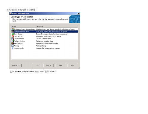
1\先将要添加的电脑节点删除!
选中 system administrator点击 Next继续 NEXT
选中 remove client 然后 NEXT
选中要删除的节点(如OS2012),点击 next 等待删除节点完成,需要等待一分钟左右。
(我这边电脑较慢)
2、将电脑计算机名称及域名更改。
重新命名计算机名称,检查域名是否正确!检查网络设置是都正确,IP地址最好也换一个!
3、重新添加到域!!
选择 ADD CLIENT 点击next
在 client NODE 下拉菜单中找到要添加的计算机名称。
点击NEXT 等待域添加成功。
然后该计算机需要等待半小时左右(我这边电脑较慢),等待C:下OperateITTemp文件(好像是这个文件,记得不是很清楚了)不再增大后,便可登陆系统了!。
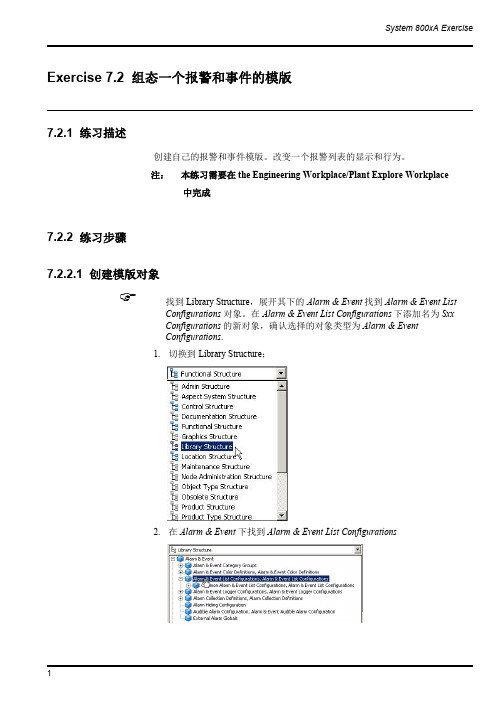
System 800xA Exercise 1Exercise 7.2组态一个报警和事件的模版7.2.1练习描述创建自己的报警和事件模版。
改变一个报警列表的显示和行为。
注:本练习需要在the Engineering Workplace/Plant Explore Workplace中完成7.2.2练习步骤7.2.2.1创建模版对象找到Library Structure ,展开其下的Alarm &Event 找到Alarm &Event ListConfigurations 对象。
在Alarm &Event List Configurations 下添加名为Sxx Configurations 的新对象,确认选择的对象类型为Alarm &Event Configurations .1.切换到Library Structure;2.在Alarm &Event 下找到Alarm &Event ListConfigurations2 3.创建一个类型为Alarm &Event List Configurations 的新对象,命名为Sxx_Configurations☞拷贝位于Common Alarm &Event Configurations 组中的Common Alarm ListConfiguration 对象。
1.选择Common Alarm List Configuration对象并拷贝它☞将其作为一个子对象粘贴到Sxx Configurations 组下。
1.选择Sxx_Configurations 对象并粘贴。
Exercise6.3Creating a Faceplate for the User_defined Function Block(Optional)6.3.1DescriptionWe are going create a solution with a block,called myTank_FB,.It will have thefollowing characteristics.∙A variable called TankLevel,which represents the level in the Tank∙A variable FlowSpeed,which sets the speed of filling∙A variable called OnOff which starts/stops the filling of the Tank∙A parameter MaxAlarm which sets the level for a HH Alarm∙A parameter MinAlarm which sets the level for a LL AlarmWe would like to have the following aspects connected to the myTank_FB∙Graphical Element showing the Tank,the name,the alarm limits and the Level∙A Faceplate for control of the Tank∙Trend Display showing the Level∙A history log logging the Level∙An Alarm and Event list showing the Tank Alarms6.3.2Solution StepsProcess Portal A and Control Builder is an an integrated DCS System.This means thatyou only need to engineering they system once.All objects that you create in theControl Builder will automatically appear in Process Portal and vice versa.6.3.2.1Start Plant ExplorerStart Plant Explorer and open navigate to the Control StuctureOpen the Project in the Control StructureIt may take a minute or two to open the Project.6.3.2.2Create a new of ProgramCreate a new Program and call it Exercise and assign a Task to the it.Process Portalgets confused if you have several applications with the same name.Be sure to select aunique name for your application.Attach it to a Task in the Controller6.3.2.3Creation of your LibraryThe next step is to create a library,so we can re-use the solution we create today inseveral projects.Create a Library called YourName DemoLib,for example demoLib.6.3.2.4Creation of myTank_FBIn the library we should create a function block type called myTank_FB.Control Builder is part of the Industrial IT,which leads to that what you create in theControl Builder is also created in the Plant Explorer.Create the functionality of the Tank Block as described below.We will later increasethe functionality.Note that you need to be in the Control Builder to makes the changes in the code.Either you switch to the Control Builder using the Tabs or you can right mouse clickon you Function Block in Plant Explorer and select Function Block Editor.Code and ParametersVariables6.3.2.5Creation of Graphic Element on myTank_FBThe next step is to create a Graphic Element on the myTank_FB type in Process Portal.We want to create a Graphic Element that shows the value of Level in a NumericDisplay and in a Bar Graph and show the name of the function block.Locate the myTank_FB in the Object Type Structure and select New Aspect.Create a new Graphic Element PG2and call it Graphic Element.Edit the element.Create the static part as followsI used the following elements1.For the tank top,bottom and body2.For the Name3.For the Bar Graph4.For the Numeric LevelIt is time to connect the elements to the process.What we are going to use it the Expression Builder.By doing this is in Object Type Structure we assign the variables relatively to the Tank Object Type.This means that the assignments will work for any tank that we create,i.e.we do not need to assign the Name and the Level to each Tank. It is done automatically.Select the Numeric and jump to the properties window.Set the parameter No1~5aswell as the blow graphic.Adjust the No.6parameter to a proper value.For the No.7parameter,jump to the Expression Editor from selecting radio buttons within the Properties Window to add dynamic value:TankLevel.Continue to add the Level to the input of the BarGraph.Connect the TextElement’s Text property to the Name of the Function Block.Save the graphic and test the behavior.Testing,while in the Graphic Editor,can be done by“View>Test Data”.Take a look in the Object Type Structure on the graphic element.6.3.2.6Creation of the your first programLets create a small application consisting of two instances of the myTank_FB and testthe functionality.We will use the Function Block Editor to write our application inProgram2Connect LibrariesThe first step we need to do is to Connect the myUserLib to our Application.Go theControl Structure and select your application.Press Connect LibrariesSelect myUserLib and press OK6.3.2.7Create the ProgramGo to Excise_No2and declare a Function Block called myTank1and assign FS1(Flow Speed1)to the input and set it to5.Repeat the procedure for another Tankcalled myTank2and use the input FS2(Flow Speed2)and set it to10.The solution is belowVariables and CodeFunction BlocksAs soon as you press Apply in the Editor Window you will get the Function Blocks in the Control Structure of Process Portal.This is what we call Integrated Engineering.Take a look in the Control Structure and you will see both Tanks.We would like to see if our programs works.Go to Simulate mode and test your program.Below is the Excise_No2in simulation modeYou can see the value of the parameters,but if you want to see the variables,for example the level you need to go down one level.You can do that my right mouse clicking on the function block and select“Online Editor”By doing that you get a view of the code inside the Function Block.In this mode you will see all variables inside the function block.Go download and go on-lineNow when you know your element is working,it is time to download and go-online.Remember to set you System Identity for you SoftController to your IP address(127.0.0.1:2for the SoftController)6.3.2.8Check that you have live dataYou can check that you have live data by looking at the Function Block aspects in theControl Structure.Locate the Exercise,Program1,select the Function Block and the tab Property Viewand select“Subscribe for live data”If you get values in the table you know that you have live data.If you do not get live data,make sure that you have started the OPC Server and thatyou have selected your PC as the provider.6.3.2.9Creation of the faceplate for myTank_FBNow we want to create a faceplate,to control our Level in the myTank_FB.First of all we need to add the code that makes is possible to stop the TankLevel in theTank.Go back to the Control Builder and edit the myTank_FB by adding an OnOff variableand use it as below.Create the FaceplateThe Faceplate is the main aspect for the faceplate.Locate the myTank_FB in theObject Type Structure and create a Faceplate PG2aspect named Faceplate.Take a look at the faceplate.At this moment it is just empty.We would like to fill it with some information and some actions buttons.The first step is to select the Config view and create two buttons On and Off to set the value of the running variable.Switch to Config View and select the Buttons tab.Click Icon/Labels to specify what icon or text you want to have on the button.The next step is to select what property we want to set.This button should set the OnOff.The third step is to set what property value we should write to the controller when we push the button.We would like to write True to the OnOff when we push the Open Button.You can also supply a tool tip.The last thing you need to do is to select in what positions the button should appear.The positions are numbered from left to right. Repeat the procedure for the Close Buttons.Call it C.The last thing you need to do is to set the position of the Button in the Faceplate.Go back to the Faceplate View and take a look at your Faceplate.Go back to the Control Structure and select the Overview Graphics on Excise_No2. Right mouse click on Tank1and select the Faceplate.Try to Open and Close the Tank.Tank2has the same functionality since we built the Faceplate on the Type.It would be nice if an operator could open the Faceplate by just clicking on the Object. It is quite easy to configure that behavior.Go back to the Object Type Structure and select the Faceplate Aspect.Right mouse click and select Properties.Select Default Aspect in the Aspect Details Tab.Go back to the Overview Graphics and click on the Tank to bring up the faceplate. Creation of a Faceplate ElementWe want to have a faceplate element in the middle of the faceplate that show a bargraph with the level.We also want to be able to set the level manually.In order to do that,we need to create a faceplate element on the myTank_FB.AFaceplate Element is an element that can accept input to the controller.Edit the faceplate element.We want to be able to click and set the level and turn the Level on and off.We are going to use the ToggleButton and the BarTie the Level to the Bar value in the Properties Window.Attach the Toggle button to the OnOff signalSave the Faceplate ElementYou need to out this faceplate element in to the faceplate.Go to the Object Type Structure and select Config View on the Faceplate and select to include the Faceplate Element in the Elements tab.Click ApplyOpen your Overview Graphics and select the Faceplate.It shall now have a nice Faceplate Element in the Faceplate.You can set the level and toggle On Off with theToggle Button.Add an indicatorWe would like to have an Indicator showing the status of the running variable.Select the ConfigView on the Faceplate in the ObjectType structure.Click in the Icons/Labels Window and supply the what shall be shown as the indicatorWe need to decide when what icon should be shown.Click in the Expression Window to supply an ExpressionIif($'.:OnOff',0,1)This expression means:Show label number0if OnOff is TRUE otherwise show label number1.Select the position to show the IndicatorOpen your Overview Graphics and select the Faceplate.It shall now have a nice Faceplate Element in the Faceplate.You can set the level and toggle On Off with the Toggle Button.6.3.2.10Creation of an Overview DisplayWe would like to have an Overview Displays that holds both of our Tanks.Go to theFunction Structure and create a new Graphic Display PG2.Right mouse click to Edit.We would,of course,like to re-use instead of creating a new Tank Element.A graphic element may be used in any graphic display.To add an element to thedisplay,select the Element Browser icon from the toolbar:All of the dynamic linking to the process data is already done.This is the power ofusing graphic elements.Therefore we are going to use the Element Explorer to selectthe Graphic Elements on our Tanks.Select myTank1and Mytank2in the Control Structure,all reusable graphic elementsare listed.This time myTank1own a graphic element named graphic element only.Select and add the graphic element in the display by several methods: -select the element and click on the edit panel-double-click the selected graphic element-drag and drop the element on to the edit panel-select the graphic element and press“Enter”.Arrange them and insert a text as a Headline.There are two modes which can be selected in the Graphics Builder:•Edit ModeThis is the default mode and allows the user to build the graphic aspect without any interactive connection to dynamic data.•Live ModeThis allows the user to view the behavior of graphic aspects with dynamic values.Please use Live mode to see result below.As you see you can have live data in the Graphics Builder.Save the Graphics.If you do not see the live data please make sure you have selected the Live Data option 6.3.2.11Add a Trend Display for myTank_FBWe would like to have a run-time trend showing the Level of the Tank.Go to theObject Type Structure and select the myTank_FB and create a Trend Display.We create Trend Display on the type.In order to get a relative path,type in“.”(youtype in a dot and the dot will be replace by the type name)for the Object.Select theFunction Block as the Aspect and the TankLevel as the property.Also set the high range to100.00Save the trend.Open your Overview Graphics and select the Trend Display.Change the time range to a minute.Configure history to log the TankLevelsWe would like to historize the TankLevel.Go to the Control Structure and create a Log Configuration Aspect on Tank1.The Log Configuration Aspect lets you define what property to log and what template to use.The template defines how to log,e.g.how often and how large of a storage each tag has.Click on the TankLevel to log it.Select the Template you would like to usePress OK and Apply.Now you TankLevel for Tank1is being Historized.Repeat the Procedure for Tank2and its TankLevel.6.3.2.12Add an Aspect Link to the Trend on the FaceplateWe want to have an Aspect Link on the faceplate to the Trend Display.Go back to theObject Type Structure and select Config View on the Faceplate and the Indicators Tab.Select the View you want the button to open.Select to use the Aspect Icon as the Icon/LabelSelect the position to be number6for all different sizes of the faceplate.Open your Overview Graphics and select the Faceplate6.3.2.13Adding Alarming to the myTank_FBConfigure the Alarm Handling for the myTank_FBIn order to get the Alarming functionality in the Controller you need to insert theAlarmEventLib into the projectConnect the Alarm&EventLib to the Application.Connect the Alarm&Event Lib to myUserLib.We will add the alarming to our myTank_FB type,which means that all our instances will get the Alarm features.Add two FunctioBlocks of the AlarmCond type,called HIHI and LOLO,to the myTank_FB.We would like to be able to change the HIHILimit and the LOLOLimit from the user interface.In order to get the correct Name displayed in the Alarm and Event List,we need to add a Name parameter and assign in the program.Declare variables and write the code as belowParametersSince we added some Parameters we needed to update the Control Logic.Download the code to the ControllerSetup AC800M/C OPC Server to collect AlarmsIf you have not configured the OPC Server to collect Alarms from your controller,please follow the steps below.(You need to do this every time you re-start yoursystem or you need to configure the OPC Server to Auto Load the configuration)Open the OPC Panel from the Start MenuType in the IP-address of your controller and press ConnectYour OPC Server is now connected to your ControllerConnect Process Portal to the OPC ServerIf you have not connected the OPC Server to Process Portal A,please follow the stepsbelow.You only need to do this onceOpen Plant Explorer and the Service Structure and locate Event collector and new aservice group object named AC800M OPC AE Collector.Add a service Provide object named AC800M OPC AE Provider in this group..Click Add and select the OPC AE Server for AC800M.Click Apply in the ServiceGroup Definition Aspect.You have now setup the Alarm Collection in Process PortalCheck the AlarmingOpen your Overview Graphics and select the Alarm List for Tank1.Note:The AlarmList was created automatically on the myTank_FB and it is configured to show alarmsonly for the selected object.You can also check the Alarms for Tank2by right mouse clicking on the Tank2andselecting the Alarm&Event List.Create an Alarm&Event List for an AreaWe would like to have an Alarm List for that shows all alarms from Tank1and Tank2.Go to Excise_No2and create an Alarm&Event listThis Alarm&Event List should show the Alarms coming from Excise_No2andbelow,i.e.myTank1and myTank2.Select the Config View on the Alarm&Event List and select“Objects and Decedents”.Press Apply.Open your Overview Graphics and select the Alarm List for Excise_No2by selectingit from the Context Menu for Excise_No2.Adding the Object DescriptionWe would like to get the Object Description from the object in the Controller to bepresented in the Alarm&Event List.To do that we need to add a parameter,called Description,on the Function Block.Goto the Control Builder and the parameter.Of course we also need to add Description variables to our instances in the ControlLogic as in blow screen dumpDownload to the controller.Now the Control Logic is prepared,but we need to do one more thing in Process Portal to get the Description available.Every time you change a Description in the controller you need to locate the Name Uploader Aspect in the Control Structure. Locate it and press upload.By doing this the descriptions on the Function Blocks inthe Controller will be transferred to Process PortalYou can bring up the Alarm&Event List,when the synchronization is done,and youshould see the object description.Include Alarm Limits in FaceplateWe would like to see the Alarm Limits in the Faceplate.Go to the Object Type Structure and select the faceplate element of myTank_FB.Select Edit.。