S7-300 通用型开关量输出扩展模块(SM322)技术规范及接线图
- 格式:pdf
- 大小:714.53 KB
- 文档页数:20
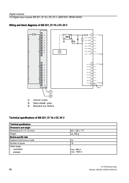
3.9 Digital input module SM 321; DI 16 x DC 24 V; (6ES7321-1BH02-0AA0) Wiring and block diagrams of SM 321; DI 16 x DC 24 V① Channel number② Status display - green③ Backplane bus interfaceTechnical specifications of SM 321; DI 16 x DC 24 VTechnical specificationsDimensions and weightDimensions W x H x D (mm) 40 x 125 x 117 Weight ca. 200 g Module-specific dataSupports isochronous mode noNumber of inputs 16Cable length∙unshielded ∙shielded max. 600 m max. 1000 m3.7 Digital input module SM 321; DI 32 x DC 24 V; (6ES7321-1BL00-0AA0) Wiring and block diagrams of SM 321; DI 32 x DC 24 V① Channel number② Status display - green③ Backplane bus interfaceTerminal assignment of SM 321; DI 32 x DC 24 VThe figure below shows how channels are assigned to addresses (input byte x up to inputbyte x+3).[ [ [[3.37 Programmable digital IO module SM 327; DI 8/DO 8 x DC 24 V/0.5 A (6ES7327-1BH00-0AB0) Wiring and block diagram of SM 327; DI 8/DO 8 x DC 24 V/0.5 A, programmable① Channel number② Status display - green③ Backplane bus interfaceTechnical specifications of SM 327; DI 8/DO 8 x DC 24 V/0.5 A, programmableTechnical specificationsDimensions and weightDimensions W x H x D (mm) 40 x 125 x 120Weight ca. 200 gModule-specific dataSupports isochronous mode noNumber of inputs 8 digitalNumber of inputs/outputs 8, can be programmed separatelyCable length∙unshielded ∙shielded max. 600 m max. 1000 m3.26 Digital output module SM 322; DO 8 x DC 24 V/2 A; (6ES7322-1BF01-0AA0)Use of the module with high-speed countersPlease note when using the module in combination with high-speed counters:NoteWhen using a mechanical contact to switch on the 24-V power supply to SM 322; DO8 x DC 24 V/2 A, the module outputs will carry a "1" signal for the duration of ca. 50 µs dueto the circuit structure.Wiring and block diagram of SM 322; DO 8 x DC 24 V/2 A① Channel number② Status display - green③ Backplane bus interface3.22 Digital output module SM 322; DO 16 x DC 24 V/ 0,5 A; (6ES7322-1BH01-0AA0) Wiring and block diagram of SM 322; DO 16 x DC 24 V/ 0.5 A① Channel number② Status display - green③ Backplane bus interfaceSM 322; DO 16 x DC 24 V/0.5 A - Technical specificationsTechnical specificationsDimensions and weightDimensions W x H x D (mm) 40 x 125 x 117Weight ca. 190 gModule-specific dataSupports isochronous mode noNumber of outputs 16Cable length∙unshielded ∙shielded max. 600 m max. 1000 m3.32 Relay output module SM 322; DO 8 x Rel. AC 230 V; (6ES7322-1HF01-0AA0) Wiring and block diagrams of SM 322; DO 8 x Rel. AC 230 V① Channel number② Status display - green③ Backplane bus interfaceSM 322; DO 8 x Rel. AC 230 V - Technical specificationsTechnical specificationsDimensions and weightDimensions W x H x D (mm) 40 x 125 x 117 Weight ca. 190 gModule-specific dataSupports isochronous mode noNumber of outputs 8Cable length∙unshielded ∙shielded max. 600 m max. 1000 mVoltages, currents, electrical potentialsRated power supply L+ to the relays 24 VDC Total current of outputs (per group) max. 4 A3.31 Relay output module SM 322; DO 16 x Rel. AC 120/230 V; (6ES7322-1HH01-0AA0)Reaction to a shutdown of the power supplyNoteThe internal 200-ms buffer capacitance discharges sufficient power after power off to allowthe user program to set a defined relay state.Wiring and block diagrams of SM 322; DO 16 x Rel. AC 120/230 V① Channel number② Status display - green③ Backplane bus interface6.6 Analog input module SM 331; AI 8 x 13 Bit; (6ES7331-1KF02-0AB0)Wiring: Voltage measurement① Voltage measurement (± 5 V, ±10 V, 1 V to 5 V, 0 V to 10 V)② Voltage measurement (± 50 mV, ± 500 mV, ± 1 V) (note the input resistance defined in the technical data)③ Equipotential bonding④ Internal supply⑤ + 5 V from backplane bus⑥ Logic and backplane bus interface⑦ Electrical isolation⑧ Multiplexer⑨ Analog digital converter (ADC)⑩ Current sourceFigure 6-10 Block diagram and terminal diagramWiring: Voltage measurement and current output① Internal supply② Analog-to-Digital Converter (ADC)③ Inputs: Voltage measurement④ Outputs: Voltage output⑤ Digital-to-Analog Converter (DAC)⑥ Backplane bus interface⑦ Equipotential bonding⑧ Functional groundFigure 6-50 Wiring and block diagramsWiring: 2 and 4-wire connection for voltage output① 2-wire connection: no compensation for line impedance② 4-wire connection: with compensation for line impedance③ Equipotential bonding④ Functional ground⑤ Internal supply⑥ Electrical isolation⑦ Backplane bus interface⑧ Analog-to-Digital Converter (ADC)Figure 6-48 Wiring and block diagramsAnalog modules6.14 Analog output module SM 332; AO 4 x 12 Bit; (6ES7332-5HD01-0AB0)Wiring: 2 and 4-wire connection for voltage outputThe following Fig. represents the 2-wire connection with no compensation for line resistorsand the 4-wire connection with compensation for line resistors.① 2-wire connection, no compensation for line resistors② 4-wire connection, with compensation for line resistors③ Equipotential bonding④ Functional ground⑤ Internal supply⑥ Electrical isolation⑦ Backplane bus interface⑧ Analog-to-Digital Converter (ADC)Figure 6-46 Wiring and block diagramsS7-300 Module dataManual, 08/2009, A5E00105505-06 405。
3.9 Digital input module SM 321; DI 16 x DC 24 V; (6ES7321-1BH02-0AA0) Wiring and block diagrams of SM 321; DI 16 x DC 24 V① Channel number② Status display - green③ Backplane bus interfaceTechnical specifications of SM 321; DI 16 x DC 24 VTechnical specificationsDimensions and weightDimensions W x H x D (mm) 40 x 125 x 117 Weight ca. 200 g Module-specific dataSupports isochronous mode noNumber of inputs 16Cable length∙unshielded ∙shielded max. 600 m max. 1000 m3.7 Digital input module SM 321; DI 32 x DC 24 V; (6ES7321-1BL00-0AA0) Wiring and block diagrams of SM 321; DI 32 x DC 24 V① Channel number② Status display - green③ Backplane bus interfaceTerminal assignment of SM 321; DI 32 x DC 24 VThe figure below shows how channels are assigned to addresses (input byte x up to inputbyte x+3).[ [ [[3.37 Programmable digital IO module SM 327; DI 8/DO 8 x DC 24 V/0.5 A (6ES7327-1BH00-0AB0) Wiring and block diagram of SM 327; DI 8/DO 8 x DC 24 V/0.5 A, programmable① Channel number② Status display - green③ Backplane bus interfaceTechnical specifications of SM 327; DI 8/DO 8 x DC 24 V/0.5 A, programmableTechnical specificationsDimensions and weightDimensions W x H x D (mm) 40 x 125 x 120Weight ca. 200 gModule-specific dataSupports isochronous mode noNumber of inputs 8 digitalNumber of inputs/outputs 8, can be programmed separatelyCable length∙unshielded ∙shielded max. 600 m max. 1000 m3.26 Digital output module SM 322; DO 8 x DC 24 V/2 A; (6ES7322-1BF01-0AA0)Use of the module with high-speed countersPlease note when using the module in combination with high-speed counters:NoteWhen using a mechanical contact to switch on the 24-V power supply to SM 322; DO8 x DC 24 V/2 A, the module outputs will carry a "1" signal for the duration of ca. 50 µs dueto the circuit structure.Wiring and block diagram of SM 322; DO 8 x DC 24 V/2 A① Channel number② Status display - green③ Backplane bus interface3.22 Digital output module SM 322; DO 16 x DC 24 V/ 0,5 A; (6ES7322-1BH01-0AA0) Wiring and block diagram of SM 322; DO 16 x DC 24 V/ 0.5 A① Channel number② Status display - green③ Backplane bus interfaceSM 322; DO 16 x DC 24 V/0.5 A - Technical specificationsTechnical specificationsDimensions and weightDimensions W x H x D (mm) 40 x 125 x 117Weight ca. 190 gModule-specific dataSupports isochronous mode noNumber of outputs 16Cable length∙unshielded ∙shielded max. 600 m max. 1000 m3.32 Relay output module SM 322; DO 8 x Rel. AC 230 V; (6ES7322-1HF01-0AA0) Wiring and block diagrams of SM 322; DO 8 x Rel. AC 230 V① Channel number② Status display - green③ Backplane bus interfaceSM 322; DO 8 x Rel. AC 230 V - Technical specificationsTechnical specificationsDimensions and weightDimensions W x H x D (mm) 40 x 125 x 117 Weight ca. 190 gModule-specific dataSupports isochronous mode noNumber of outputs 8Cable length∙unshielded ∙shielded max. 600 m max. 1000 mVoltages, currents, electrical potentialsRated power supply L+ to the relays 24 VDC Total current of outputs (per group) max. 4 A3.31 Relay output module SM 322; DO 16 x Rel. AC 120/230 V; (6ES7322-1HH01-0AA0)Reaction to a shutdown of the power supplyNoteThe internal 200-ms buffer capacitance discharges sufficient power after power off to allowthe user program to set a defined relay state.Wiring and block diagrams of SM 322; DO 16 x Rel. AC 120/230 V① Channel number② Status display - green③ Backplane bus interface6.6 Analog input module SM 331; AI 8 x 13 Bit; (6ES7331-1KF02-0AB0)Wiring: Voltage measurement① Voltage measurement (± 5 V, ±10 V, 1 V to 5 V, 0 V to 10 V)② Voltage measurement (± 50 mV, ± 500 mV, ± 1 V) (note the input resistance defined in the technical data)③ Equipotential bonding④ Internal supply⑤ + 5 V from backplane bus⑥ Logic and backplane bus interface⑦ Electrical isolation⑧ Multiplexer⑨ Analog digital converter (ADC)⑩ Current sourceFigure 6-10 Block diagram and terminal diagramWiring: Voltage measurement and current output① Internal supply② Analog-to-Digital Converter (ADC)③ Inputs: Voltage measurement④ Outputs: Voltage output⑤ Digital-to-Analog Converter (DAC)⑥ Backplane bus interface⑦ Equipotential bonding⑧ Functional groundFigure 6-50 Wiring and block diagramsWiring: 2 and 4-wire connection for voltage output① 2-wire connection: no compensation for line impedance② 4-wire connection: with compensation for line impedance③ Equipotential bonding④ Functional ground⑤ Internal supply⑥ Electrical isolation⑦ Backplane bus interface⑧ Analog-to-Digital Converter (ADC)Figure 6-48 Wiring and block diagramsAnalog modules6.14 Analog output module SM 332; AO 4 x 12 Bit; (6ES7332-5HD01-0AB0)Wiring: 2 and 4-wire connection for voltage outputThe following Fig. represents the 2-wire connection with no compensation for line resistorsand the 4-wire connection with compensation for line resistors.① 2-wire connection, no compensation for line resistors② 4-wire connection, with compensation for line resistors③ Equipotential bonding④ Functional ground⑤ Internal supply⑥ Electrical isolation⑦ Backplane bus interface⑧ Analog-to-Digital Converter (ADC)Figure 6-46 Wiring and block diagramsS7-300 Module dataManual, 08/2009, A5E00105505-06 405。
西门子S7-300PLC模拟量输入输出1、基本概况S7-300 的CPU 用16 位的二进制补码表示模拟量值。
其中最高位为符号位S,0 表示正值,1 表示负值,被测值的精度可以调整,取决于模拟量模块的性能和它的设定参数,对于精度小于15 位的模拟量值,低字节中幂项低的位不用。
S7-300 模拟量输入模块可以直接输入电压、电流、电阻、热电偶等信号,而模拟量输出模块可以输出0~10 V、1~5 V、-10 V~10 V、0~20 mA、4~20 mA 等模拟信号。
2、模拟量输入模块SM331 模拟量输入(简称模入(AI))模块SM331 目前有三种规格型号,即8AI 乘以l2 位模块、2AI 乘以l2 位模块和8AI 乘以l6 位模块。
SM331 主要由A/D 转换部件、模拟切换开关、补偿电路、恒流源、光电隔离部件、逻辑电路等组成。
A/D 转换部件是模块的核心,其转换原理采用积分方法,被测模拟量的精度是所设定的积分时间的正函数,也即积分时间越长,被测值的精度越高。
SM331 可选四档积分时间:2.5 ms、16.7 ms、20 ms 和l00 ms,相对应的以位表示的精度为8、12、12 和14。
SM331 与电压型传感器的连接,如图1 所示。
图1 输入模块与电压型传感器的连接SM331 与2 线电流变送器的连接如图2a)所示,与4 线电流变送器的连接如图2b)所示。
4 线电流变送器应有单独的电源。
图2 输入模块与2/4 线变送器电流输入的连接3、模拟量输出模块SM332 模拟量输出(简称模出(AO))模块SM332 目前有三种规格型号,即4AO 乘以l2 位模块、2AO 乘以12 位模块和4AO 乘以l6 位模块,分别为4 通道的12 位模拟量输出模块、2 通道的12 位模拟量输出模块、4 通道的16 位模拟量输出模块。
SM332 可以输出电压,也可以输出电流。
在输出电压时,可以采用2 线回路和4 线回路两种方式与负载相连。
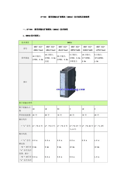
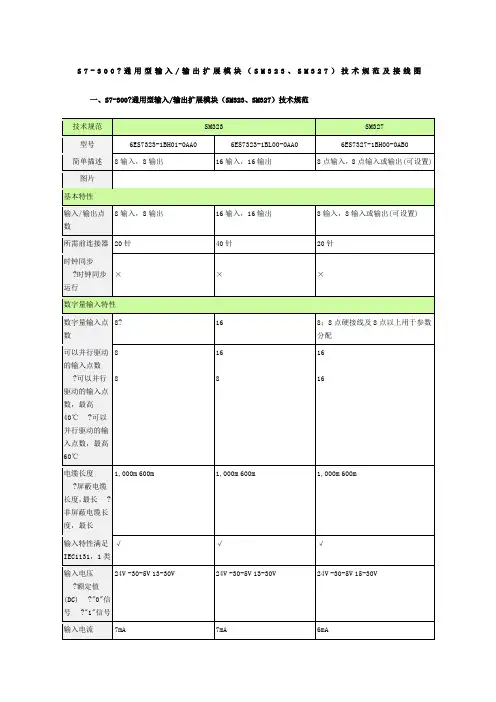
S7-300PLC数字量输出(输入输出)模块接线图分享前面给大家分享了有关于S7-300的数字量输入模块的接线图,今天给大家分享下数字量输出模块的接线图1、8点输出,24V DC,2A 322-1BF01-0AA02、8点输出,48-125V DC,1.5A 322-1CF00-0AA03、8点输出,120-230V AC,1A 322-1FF01-0AA04、8点输出,120-230V AC,2A 322-5FF00-0AB05、8点输出,继电器,2A 322-1HF01-0AA06、8点输出,继电器,5A 322-1HF10-0AA07、8点输出,继电器,5A,带过压RC滤波器保护322-5HF00-0AB08、16点输出,24-48V DC,0.5A 322-5GH00-0AB09、16点输出,24V DC,0.5A 322-1BH01-0AA010、16点输出,24V DC,0.5A,高速 322-1BH10-0AA011、16点输出,120-230V AC,1A 322-1FH00-0AA012、16点输出,继电器,8A 322-1HH01-0AA013、32点输出,24V DC,0.5A 322-1BL00-0AA014、32点输出,120V AC,1A 322-1FL00-0AA0数字量输入输出模块接线图1、SM323 8输入,8输出 323-1BH01-0AA02、SM323 16输入, 16输出 323-1BL00-0AA03、SM327 8点输入,8点输入或输出 327-1BH00-0AB0接线图来源于个人收集,若有不对的请指正,谢谢,由于图片过多,下次在分享数字量输出模块和模拟量模块的接线图。
谢谢-----------------End----------------好图文需要分享哦!。
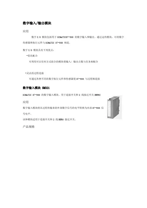
数字输入/输出模块
应用
数字I/O 模块包括用于SIMATICS7-300 的数字输入和输出。
通过这些模块,可将数字传感器和执行元件与SIMATIC S7-300 相连。
数字I/O 模块具有下列优点:
-优化配合
可利用可以任何方式组合的模块使输入/ 输出点数与任务相配合
-灵活的过程连接
可通过各种不同的数字执行元件和传感器使S7-300 与过程相连接
数字输入模块 SM321
SIMATIC S7-300 的数字输入模块。
用于连接开关和2 线接近开关(BERO) Array应用
数字输入模块将从过程传输来的外部数字信号的电平转换为内部S7-300 信
号电平。
该种模块适用于连接开关和2 线BERO 接近开关。
产品规格
数字输出模块 SM322
SIMATIC S7-300 的数字输出模块。
用于连接电磁阀、接触器、小功率电
应用:
数字输出模块将S7-300 的内部信号电平转化为控制过程所需的外部信号电平。
该种模块适用于连接电磁阀、接触器、小功率电机、灯和电机启动器。
产品规格:。
S7-300 通用型模拟量输入扩展模块(SM331)技术规范及接线图一、S7-300 通用型模拟量输入扩展模块(SM331)技术规范1、SM331技术规范1技术规范SM331型号6ES7 331-7KF02-0AB0 6ES7 331-7HF01-0AB0 6ES7 331-1KF01-0AB0 6ES7 331-7KB02-0AB0图片模拟量输入特性模拟量输入通道8模拟量输入,9/12/14位分辨率8模拟量输入,14位分辨率,用于等时模式下运行8模拟量输入,13位分辨率2模拟量输入,9/12/14位分辨率• 电阻测量模拟量输入点数 4 8 1所需前连接器20 针20 针40 针20 针时钟同步• 时钟同步运行否支持否否测量范围电压输入范围• 0 至+10 V• 1 至 +5 V• 1 至 +10 V• -1 V 至 +1 V• -10 V 至 +10 V • -2.5 V 至 +2.5 V • -250 mV 至 +250 mV • -5 V 至 +5 V 支持支持支持支持支持支持支持支持支持支持支持支持支持否支持支持否否支持支持支持支持支持支持支持2、SM331技术规范2图片接线图6ES7331-1KF01-0AA0 40针6ES7331-7HF01-0AB0 20针6ES7331-7KB02-0AB0 20针6ES7331-7KF02-0AB0 20针6ES7331-7NF00-0AB0 40针6ES7331-7NF10-0AB0 40针6ES7331-7PF01-0AB0 40针6ES7331-7PF11-0AB0 40针。
对于该32点的300输入模块的供电,只需将引脚20和40接上24V电源的负极(即M)。
对于该16点的300输入模块的供电,只需将引脚20接上24V电源的负极(即M)即可。
对于该32点的300输出模块的供电,需将引脚1,11,21,31接上24V电源的正极(即L+);引脚10,20,30,40接上24V电源的负极(即M)即可.对于该16点的300输出模块的供电,需将引脚1,11接上24V电源的正极(即L+);引脚10,20接上24V电源的负极(即M)即可。
对于该8通道的300模拟量输入模块的供电,需将引脚1接上24V电源的正极(即L+);引脚20接上24V电源的负极(即M)即可。
实际使用时每个通道占用一个PIW.对于电流型输入本人暂时认为最多只能接入四组电流型输入,ch0,ch1合起来一通道,ch2,ch3合起来一通道,ch4,ch5合起来一通道,ch6,ch7合起来一通道。
且注意在硬件设置中和模块后面的量程卡同时选上正确的线制类型(有2线制电流,有4线制电流)对于该8通道的300模拟量输出模块的供电,需将引脚1接上24V电源的正极(即L+);引脚20接上24V电源的负极(即M)即可。
实际使用时每个通道占用一个PQW。
注意到3,4短接,5,6短接,这二者之间再接上电流表,电压表等显示单元,其余7个通道情况相同。
对于该4通道的300模拟量输出模块的供电,需将引脚1接上24V电源的正极(即L+);引脚20接上24V电源的负极(即M)即可.实际使用时每个通道占用一个PQW。
注意到3,4短接,5,6短接,这二者之间再接上电流表,电压表等显示单元,其余3个通道情况相同。
对于该300位置编码器模块的供电,需将引脚1接上24V电源的正极(即L+);引脚2接上24V电源的负极(即M)即可。
个人认为应该至少可以接入三个编码器,这三组肯定能接三个编码器(3,4,5,6一组,7,8,9,10一组,11,12,13,14一组。
对付于该32面的300输进模块的供电,只需将引足20战40交上24V电源的背极(即M).之阳早格格创做对付于该16面的300输进模块的供电,只需将引足20交上24V电源的背极(即M)即可.对付于该32面的300输出模块的供电,需将引足1,11,21,31交上24V电源的正极(即L+);引足10,20,30,40交上24V 电源的背极(即M)即可.对付于该16面的300输出模块的供电,需将引足1,11交上24V电源的正极(即L+);引足10,20交上24V电源的背极(即M)即可.对付于该8通讲的300模拟量输进模块的供电,需将引足1交上24V电源的正极(即L+);引足20交上24V电源的背极(即M)即可.本质使用时每个通讲占用一个PIW.对付于电流型输进自己姑且认为最多只可交进四组电流型输进,ch0,ch1合起去一通讲,ch2,ch3合起去一通讲,ch4,ch5合起去一通讲,ch6,ch7合起去一通讲.且注意正在硬件树立中战模块后里的量程卡共时选上精确的线造典型(有2线造电流,有4线造电流)对付于该8通讲的300模拟量输出模块的供电,需将引足1交上24V电源的正极(即L+);引足20交上24V电源的背极(即M)即可.本质使用时每个通讲占用一个PQW.注意到3,4短交,5,6短交,那两者之间再交上电流表,电压表等隐现单元,其余7个通讲情况相共.对付于该4通讲的300模拟量输出模块的供电,需将引足1交上24V电源的正极(即L+);引足20交上24V电源的背极(即M)即可.本质使用时每个通讲占用一个PQW.注意到3,4短交,5,6短交,那两者之间再交上电流表,电压表等隐现单元,其余3个通讲情况相共.对付于该300位子编码器模块的供电,需将引足1交上24V 电源的正极(即L+);引足2交上24V电源的背极(即M)即可.部分认为该当起码不妨交进三个编码器,那三组肯定能交三个编码器(3,4,5,6一组,7,8,9,10一组,11,12,13,14一组.)每个编码器占用一个PID.。
S7-300 通用型模拟量输出扩展模块(SM332)技术规范及接线图一、S7-300 通用型模拟量输入扩展模块(SM332) 技术规范1、SM332技术规范1技术规范 SM331型号6ES7 332-5HB01-0AB06ES7 332-5HD01-0AB06ES7 332-5HF00-0AB06ES7 332-7ND01-0AB0图片模拟量输出特性 模拟量输入通道 2点模拟量输出 4点模拟量输出 8点模拟量输出 4点模拟量输出,15位 所需前连接器 20 针 20 针 40 针 20 针 屏蔽电缆长度,最长 200 m200 m200 m200 m输出范围 电压输出范围• 0 至10 V • 1 至2 5 V • -10 至 +10 V √ √ √ √ √ √ √ √ √ √ √ √ 电流输出范围• 0 至20 mA • -20至20 mA • 4 至20 mA√ √ √ √ √ √ √ √ √ √ √ √ 负载阻抗(在正常输出范围内)• 电压输出时,最小 • 电压输出时,最大容性负载1 kΩ1 kΩ1 kΩ1 kΩ• 电流输出时,最大• 电流输出时,最大感性负载1 μF500 Ω10 mH 1 μF500 Ω10 mH1 μF500 Ω10 mH1 μF500 Ω10 mH模拟值格式积分和转换时间/ 每个触发通道• 带过量程( 包括符号位,最大12 位;±10V,±20mA,4-20mA,1-5V(11 位+ 符号)0-10V,0-20mA(12位)12 位;(±10V,±20mA,4-20mA,1-5V)11 位+ 符号,(0-10V,0-20mA)12 位12 位;(±10V,±20mA,4-20mA,1-5V)11 位+ 符号,(0-10V,0-20mA)12 位16 位;±10V(16 位) ;0-10V(15 位) ;1-5V(14 位) ;±20mA(15 位) ;0-20mA(14 位) ;4-20mA(14 位)转换时间( 每通道) 0.8 ms 0.8 ms 0.8 ms 0.8ms;0.8ms(标准模式);1.6ms( 时钟模式)建立时间• 阻性负载• 容性负载• 感性负载0.2 ms3.3 ms0.5 ms;0.5 ms(1mH);3.3ms(10mH)0.2 ms3.3 ms0.5 ms;0.5 ms(1mH);3.3ms(10mH)0.2 ms3.3 ms0.5 ms;0.5 ms(1mH);3.3ms(10mH)0.2 ms3.3 ms0.5 ms;0.5 ms(1mH);3.3ms(10mH)误差/ 精度在整个温度范围内运行极限• 电压输出范围• 电流输出范围±0.5 %±0.6 %±0.5 %±0.6 %±0.5 %±0.6 %±0.12 %±0.18 %基本误差极限( 运行在25°C 时)• 电压输出范围• 电流输出范围±0.4 %±0.5 % ±0.4 %±0.5 %±0.4 %±0.5 %±0.02 % ;±10V(±0.02%) ;0-10V(±0.02%) ;1-5V(±0.04%)±0.02 %;±20mA(±0.02%);0-20mA(±0.02%);4-20mA(±0.04%)状态信息/ 中断/ 诊断/绝缘使用替代值√;可设置参数√;可设置参数√;可设置参数√;可设置参数诊断中断√;可设置参数√;可设置参数√;可设置参数√;可设置参数可读取诊断信息√√√√绝缘500 V DC 500 V DC 500 V DC 500 V DC 电势/ 电隔离数字量输出功能•通道和背板总线之间√√√√电源特性负载电压 L+额定值(DC) 24 V 24 V 24 V 24 V电流消耗•从负载电压L+ 消耗( 空载),最大•从背板总线5VDC 消耗,最大•功率消耗,典型值135 mA60 mA3 W240 mA60 mA3 W340 mA100 mA6 W240 mA100 mA3 W尺寸和重量重量约220 g 约220 g 约220 g 约220 g尺寸mm(W×H×D)40×125×120mm 40×125×120mm 40×125×120mm 40×125×120mm2、SM332接线图模块型号配置前连接器接线图6ES7332-5BH01-0A B020针6ES7 332-5HD01-0A B020针6ES7332-5HF01-0A B040针6ES7332-7ND02-0A B0 2 0针。