UT58A数字万用表电原理图
- 格式:docx
- 大小:480.77 KB
- 文档页数:2
万⽤表的基本⼯作原理和使⽤⽅法图解⼀、万⽤表的基本⼯作原理“万⽤表”是万⽤电表的简称,它是我们电⼦制作中⼀个必不可少的⼯具。
万⽤表能测量电流、电压、电阻、有的还可以测量三极管的放⼤倍数,频率、电容容量⼤⼩、逻辑电位、分贝值等。
万⽤表有很多种,现在最流⾏的有机械指针式的和数字式的万⽤表。
它们各有其优缺点;对于电⼦初学者,建议使⽤指针式万⽤表,因为它对我们熟悉⼀些电⼦知识原理很有帮助。
下⾯主要介绍⼀下机械指针式万⽤表的测量原理。
此类万⽤表的基本原理是利⽤⼀只灵敏的磁电式直流电流表(微安表)做表头。
当微⼩电流通过表头,就会有电流指⽰。
但表头不能通过⼤电流,所以,必须在表头上并联与串联⼀些电阻进⾏分流或降压,从⽽测出电路中的电流、电压和电阻。
下⾯分别给予介绍。
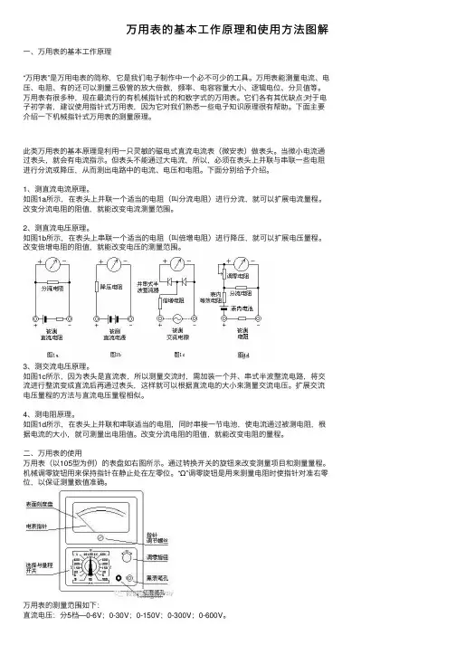
1、测直流电流原理。
如图1a所⽰,在表头上并联⼀个适当的电阻(叫分流电阻)进⾏分流,就可以扩展电流量程。
改变分流电阻的阻值,就能改变电流测量范围。
2、测直流电压原理。
如图1b所⽰,在表头上串联⼀个适当的电阻(叫倍增电阻)进⾏降压,就可以扩展电压量程。
改变倍增电阻的阻值,就能改变电压的测量范围。
3、测交流电压原理。
如图1c所⽰,因为表头是直流表,所以测量交流时,需加装⼀个并、串式半波整流电路,将交流进⾏整流变成直流后再通过表头,这样就可以根据直流电的⼤⼩来测量交流电压。
扩展交流电压量程的⽅法与直流电压量程相似。
4、测电阻原理。
如图1d所⽰,在表头上并联和串联适当的电阻,同时串接⼀节电池,使电流通过被测电阻,根据电流的⼤⼩,就可测量出电阻值。
改变分流电阻的阻值,就能改变电阻的量程。
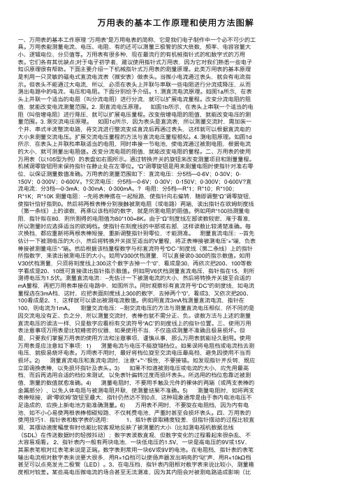
⼆、万⽤表的使⽤万⽤表(以105型为例)的表盘如右图所⽰。
通过转换开关的旋钮来改变测量项⽬和测量量程。
机械调零旋钮⽤来保持指针在静⽌处在左零位。
“Ω”调零旋钮是⽤来测量电阻时使指针对准右零位,以保证测量数值准确。
万⽤表的测量范围如下:直流电压:分5档—0-6V;0-30V;0-150V;0-300V;0-600V。
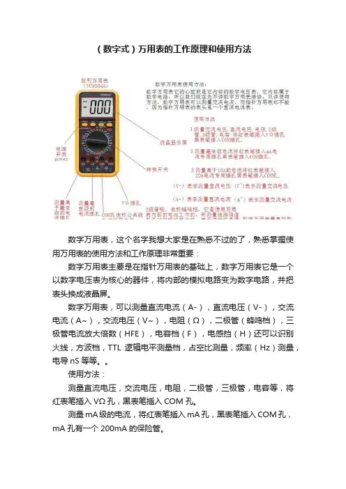
(数字式)万用表的工作原理和使用方法数字万用表,这个名字我想大家是在熟悉不过的了,熟悉掌握使用万用表的使用方法和工作原理非常重要:数字万用表主要是在指针万用表的基础上,数字万用表它是一个以数字电压表为核心的器件,将内部的模拟电路变为数字电路,并把表头换成液晶屏。
数字万用表,可以测量直流电流(A-),直流电压(V-),交流电流(A~),交流电压(V~),电阻(Ω),二极管(蜂鸣档),三极管电流放大倍数(HFE),电容档(F),电感挡(H)还可以识别火线,方波档,TTL逻辑电平测量档,占空比测量,频率(Hz)测量,电导nS等等。
使用方法:测量直流电压,交流电压,电阻,二极管,三极管,电容等,将红表笔插入VΩ孔,黑表笔插入COM孔。
测量mA级的电流,将红表笔插入mA孔,黑表笔插入COM孔,mA孔有一个200mA的保险管。
测量高于mA级别的电流将红表笔插入20A或10A电流专用插孔,黑表笔插入COM孔。
COM孔也称公共端是专门插入黑表笔的插孔。
主板维修中,使用2级管档测量对地阻值对地阻值方法将数字万用表打到2级管档红表笔接地黑表笔测量使用直流20V电压档测量主板上电压电压法将数字万用表打到直流20V电压档黑表笔接地红表笔去测量。
使用电阻档测量主板上电阻的阻值。
注意:2级管档和电阻档测量对地阻值的数值不一样。
数字万用表二级管档测量原理二级管档也称蜂鸣档,主要是在 2级管档基础上加一个蜂鸣器.数字万用表内部的电路测量电压是电阻串联分压,测量电流时电阻并联分流,只不过是测量出来的数据统一给A/D(数模转换器)通过它处理出来的信号显示到显示器上。
蜂鸣档:9V直流电压作为电源在将红黑表笔分别接触一根导线的两端9V的电压流出来的电流通过红表笔流会黑表笔构成回路电流流过蜂鸣器如果电流高的话蜂鸣器会响,在这里测量的线路阻值低于70欧蜂鸣器就会响。
数字万用表的工作原理:数字表的核心是它的A/D转换器,也就是模数转换器,将被测量的模拟信号变为数字信号给LCD液晶屏显示。
万⽤表的基本⼯作原理和使⽤⽅法图解⼀、万⽤表的基本⼯作原理 “万⽤表”是万⽤电表的简称,它是我们电⼦制作中⼀个必不可少的⼯具。
万⽤表能测量电流、电压、电阻、有的还可以测量三极管的放⼤倍数,频率、电容容量⼤⼩、逻辑电位、分贝值等。
万⽤表有很多种,现在最流⾏的有机械指针式的和数字式的万⽤表。
它们各有其优缺点;对于电⼦初学者,建议使⽤指针式万⽤表,因为它对我们熟悉⼀些电⼦知识原理很有帮助。
下⾯主要介绍⼀下机械指针式万⽤表的测量原理。
此类万⽤表的基本原理是利⽤⼀只灵敏的磁电式直流电流表(微安表)做表头。
当微⼩电流通过表头,就会有电流指⽰。
但表头不能通过⼤电流,所以,必须在表头上并联与串联⼀些电阻进⾏分流或降压,从⽽测出电路中的电流、电压和电阻。
下⾯分别给予介绍。
1. 测直流电流原理。
如图1a所⽰,在表头上并联⼀个适当的电阻(叫分流电阻)进⾏分流,就可以扩展电流量程。
改变分流电阻的阻值,就能改变电流测量范围。
2. 测直流电压原理。
如图1b所⽰,在表头上串联⼀个适当的电阻(叫倍增电阻)进⾏降压,就可以扩展电压量程。
改变倍增电阻的阻值,就能改变电压的测量范围。
3. 测交流电压原理。
如图1c所⽰,因为表头是直流表,所以测量交流时,需加装⼀个并、串式半波整流电路,将交流进⾏整流变成直流后再通过表头,这样就可以根据直流电的⼤⼩来测量交流电压。
扩展交流电压量程的⽅法与直流电压量程相似。
4. 测电阻原理。
如图1d 所⽰,在表头上并联和串联适当的电阻,同时串接⼀节电池,使电流通过被测电阻,根据电流的⼤⼩,就可测量出电阻值。
改变分流电阻的阻值,就能改变电阻的量程。
⼆、万⽤表的使⽤万⽤表(以105型为例)的表盘如右图所⽰。
通过转换开关的旋钮来改变测量项⽬和测量量程。
机械调零旋钮⽤来保持指针在静⽌处在左零位。
“Ω”调零旋钮是⽤来测量电阻时使指针对准右零位,以保证测量数值准确。
万⽤表的测量范围如下:直流电压:分5档—0-6V;0-30V;0-150V;0-300V;0-600V。
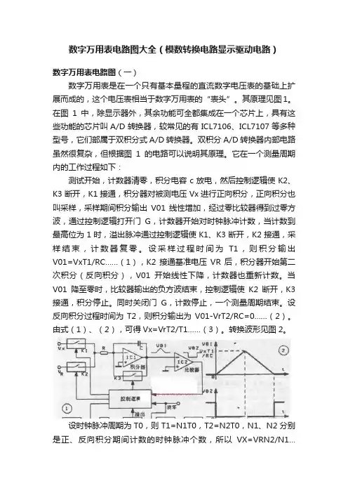
数字万用表电路图大全(模数转换电路显示驱动电路)数字万用表电路图(一)数字万用表是在一个只有基本量程的直流数字电压表的基础上扩展而成的,这个电压表相当于数字万用表的“表头”。
其原理见图1。
在图1中,除显示器外,其余功能可全都集成在一个芯片上,具有这些功能的芯片叫A/D转换器,较常见的有ICL7106、ICL7107等多种型号,它们部属于双积分式A/D转换器。
双积分A/D转换器内部电路虽然很复杂,但根据图1的电路可以说明其原理。
它在一个测量周期内的工作过程如下:测试开始,计数器清零,积分电容c放电,然后控制逻辑使K2、K3断开,K1接通,积分器对被测电压Vx进行正向积分,正向积分也叫采样,采样期间积分输出V01线性增加,经过零比较器得到过零方波,通过控制逻辑打开门G,计数器开始对时钟脉冲计数,当计数到最高位为1时,溢出脉冲通过控制逻辑使K1、K3断开,K2接通,采样结束,计数器复零。
设采样过程时间为T1,则积分输出V01=VxT1/RC……(1),K2接通基准电压VR后,积分器开始第二次积分(反向积分),V01开始线性下降,计数器也重新计数。
当V01降至零时,比较器输出的负方波结束,控制逻辑使K2断开,K3接通,积分停止。
同时关闭门G,计数停止,一个测量周期结束。
设反向积分过程时间为T2,则积分输出为V01-VrT2/RC=0……(2)。
由式(1)、(2),可得Vx=VrT2/T1……(3)。
转换波形见图2。
设时钟脉冲周期为T0,则T1=N1T0,T2=N2T0,N1、N2分别是正、反向积分期间计数的时钟脉冲个数,所以VX=VRN2/N1…(4)。
对干31/2位A/D转换器,采样期间计数到1000个脉冲时计数器有溢出,故N1=1000是个定值,如再规定VR=100.0mV,则有VX=0.1N2……(5)。
(5)式说明,适当选择N1及VR的值,可使VX与N2的有效数字相同,只是小数点位置不同。
如将小数点定在显示值N2的十位,便可直接读数。
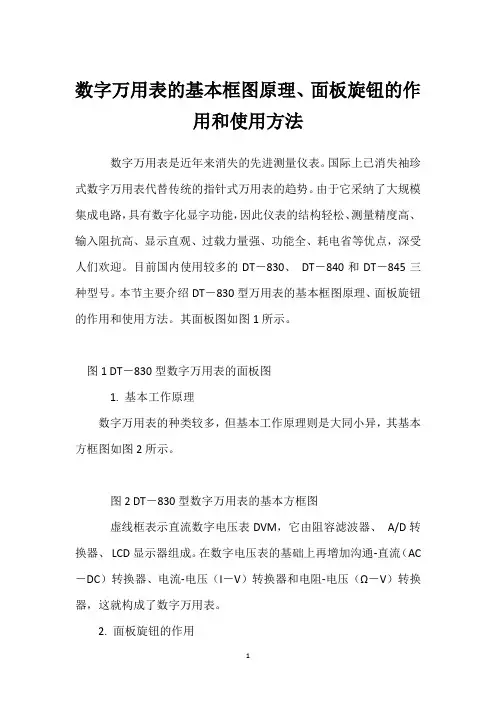
数字万用表的基本框图原理、面板旋钮的作用和使用方法数字万用表是近年来消失的先进测量仪表。
国际上已消失袖珍式数字万用表代替传统的指针式万用表的趋势。
由于它采纳了大规模集成电路,具有数字化显字功能,因此仪表的结构轻松、测量精度高、输入阻抗高、显示直观、过载力量强、功能全、耗电省等优点,深受人们欢迎。
目前国内使用较多的DT-830、DT-840和DT-845三种型号。
本节主要介绍DT-830型万用表的基本框图原理、面板旋钮的作用和使用方法。
其面板图如图1所示。
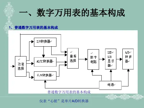
图1 DT-830型数字万用表的面板图1. 基本工作原理数字万用表的种类较多,但基本工作原理则是大同小异,其基本方框图如图2所示。
图2 DT-830型数字万用表的基本方框图虚线框表示直流数字电压表DVM,它由阻容滤波器、A/D转换器、LCD显示器组成。
在数字电压表的基础上再增加沟通-直流(AC -DC)转换器、电流-电压(I-V)转换器和电阻-电压(Ω-V)转换器,这就构成了数字万用表。
2. 面板旋钮的作用万用表面板如图1所示,上面排列着液晶显示屏、量程开关、输入插口、hFE插口和电源开关五个部分,各部分的功能如下:(1)液晶显示屏:万用表的显示位数是4位,因最高位(千位)只能显示数字“1”或者不显示数字,故算半位,总称位(读作三位半)。
最大显示数为1999或-1999。
当测量直流电压和直流电流时,仪表有自动显示极性功能,若测量值为负,显示的数字前面将带“-”号。
当仪表输入超载时,屏上消失“1”或“-1”。
(2)量程开关:旋转式量程开关位于面板中心,是转换工作种类和量程用的。
开关四周用不同的颜色和分界线标出各种不同工作状态的范围。
(3)输入插口:输入插口是万用表通过表笔和测量点连接的部位,共有“COM”、“V.Ω”、“mA”和“10A”四个孔。
负表笔始终置于“COM”插口,正表笔要依据工作种类和测量值的大小置于“V.Ω”、“mA”或“10A”中。
文件名称: UT58A手持万用表安全操作规程文件编号:版本号:A版文件密级:公开文件状态:批准、实施受控标识:受控拟制:x x x xxxx年 x 月 x日评审:x x x xxxx年 x 月 x日会签:审核:x x x xxxx年 x 月 x日批准:x x x xxxx年 x 月 x日修订页目录1. 目的 (1)2. 适用范围 (1)3. 角色和职责 (1)4. 安全操作要求 (1)5. 工作内容 (2)5.1. 综合指标 (2)5.2. 运行环境 (2)5.3. 技术指标 (2)5.4. 设备仪器功能名称 (3)5.4.1. 测量操作说明 (4)5.5. 结束生产 (9)5.5.1. 日常生产结束 (9)5.6. 禁止项目 (9)6. 日常点检及保养 (9)6.1.1. 日常点检............................................................................................... 错误!未定义书签。
6.1.2. 设备维护与保养 (10)6.2. 注意事项 (10)7. 相关文件和记录 (10)UT58A手持万用表操作规范1.目的依据UT58A型新型标准数字万用表使用手册,规范UT58A手持万用表设备的操作流程,使操作员工达到安全操作、使用、日常维护事项定义,确保设备长期稳定运行,提升使用寿命与质量。
2.适用范围本规程适用于公司UT58A手持万用表的操作、点检、维护和保养。
3.角色和职责4.1)使用本机人员经过培训后操作。
2)请按照规程里有关的操作说明使用仪表,否则可能消弱或失去仪表为您提供的安全保护。
3)使用前要检查仪表和表笔,谨防任何损坏或不正常的现象,如果发现异常情况:如表笔线裸露、机壳损坏、液晶显示器无显示等,请不要使用。
严禁使用没有后盖和后盖没有盖好的仪表,否则有电击危险。
4)表笔破损必须更换,并换上同样型号或相同电器规格的表笔。
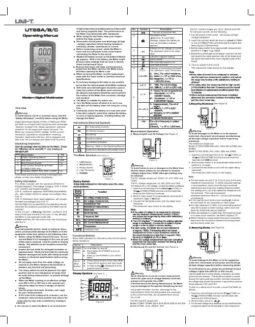
(See Figure 5)forOverviewWarningTo avoid electric shock or personal injury, read the “Safety Information”, carefully before using the Meter.Digital Multimeters Model UT58A, UT58B and UT58C are 2000-count hand-held instruments with remarkable features: ex-large LCD, steady operations, overload protection for all ranges and unique structure. The Meter can measure AC/DC voltage, AC/DC current, resistance, capacitance, temperature, frequency, transistor, diode and continuity, and is equipped with data hold, full icon display and sleep mode functions.Unpacking InspectionIn the event you find any missing or damaged part, please contact your dealer immediately.1 English Operating Manual2 Test Lead3 Multi-Purpose Socket4 Point Contact Temperature Probe (UT58B/UT58C only)59V Battery (NEDA 1604, 6F22 or 009P)Item DescriptionQty 1 pc 1 pair 1 pc 1 pc 1 pcSafety InformationThis Meter complies with the standards IEC61010:Pollution Degree 2, Overvoltage Category (CAT. II 1000V,CAT. III 600V) and Double Insulation.CAT . II: Local level, appliance, PORTABLE EQUIPMENT etc., with smaller transient voltage overvoltages than CAT. IIICAT. III: Distribution level, fixed installation, with smaller transient overvoltages than CAT. IVUse the Meter only as specified in this operating manual,otherwise the protection provided by the Meter may be impaired.In this manual, a Warning identifies conditions and actions that pose hazards to the user, or may damage the Meter or the equipment under test.A Note identifies the information that user should pay WarningTo avoid possible electric shock or personal injury,and to avoid possible damage to the Meter or to the equipment under test, adhere to the following rules:●Before using the Meter inspect the case. Do not use the Meter if it is damaged or the case (or partof the case) is removed. Look for cracks or missing plastic. Pay attention to the insulation around the connectors.●Inspect the test leads for damaged insulation orexposed metal. Check the test leads for continuity. Replace damaged test leads with identical model number or electrical specifications before using the Meter.●Do not apply more than the rated voltage, as marked on the Meter, between the terminals or between any terminal and grounding.●The rotary switch should be placed in the right position and no any changeover of range shall be made during measurement to prevent damage of the Meter.●When the Meter working at an effective voltage over 60V in DC or 30V rms in AC, special care should be taken for there is danger of electric shock.●Use the proper terminals, function, and range for your measurements.●If the value to be measured is unknown, use the maximum measurement position and reduce the range step by step until a satisfactory reading is obtained.do not alter the internal circuit of the Meter randomly.●Soft cloth and mild detergent should be used to clean the surface of the Meter when servicing.No abrasive and solvent should be used to prevent the surface of the Meter from corrosion, damage and accident.●The Meter is suitable for indoor use.●Turn the Meter power off when it is not in useand take out the battery when not using for a long time.●Constantly check the battery as it may leak when it has been using for some time, replace the battery as soon as leaking appears. A leaking battery will damage the Meter.●Do not use or store the Meter in an environmentof high temperature,humidity,explosive,inflammable and strong magnetic field. The performance of the Meter may deteriorate after dampened.●When using the test leads, keep your fingers behind the finger guards.●Disconnect circuit power and discharge all high -voltage capacitors before testing resistance, continuity, diodes, capacitance or current.●Before measuring current, check the Meter’s fuses and turn off power to the circuit before connecting the Meter to the circuit.●Replace the battery as soon as the battery indicator appears. With a low battery, the Meter might produce false readings that can lead to electric shock and personal injury.●Remove test leads, test clips and temperature probe from the Meter and turn the Meter power off before opening the Meter case.●When servicing the Meter, use the replacement parts with the same model or identical electrical specifications.●To avoid any damage to the meter or any accident,(Figure 1)The Meter Structure (See Figure 1)1.LCD Display.2.HOLD Button.3. Rotary Switch.4. Input Terminals.5.POWERFunctional ButtonsBelow table indicated for information about the functional button operations.(Figure 2)(See Figure 2)(Figure 3)WarningTo avoid harms to you or damages to the Meter from electric shock, please do not attempt to measure voltages higher than 1000V although readings may be obtained.The DC Voltage ranges are: 200mV, 2V, 20V, 200V and 1000V.The AC Voltage ranges are: 2V, 20V, 200V and 750V Measurement OperationA. Measuring DC and AC Voltage (See Figure 4)(See Figure 3)T HzV or V ΩCOM input terminal.2. Set the rotary switch to an appropriate measurement position in V or V range.3. Connect the test leads across with the object to be measured.The measured value shows on the display.(figure 4)WarningNever attempt an in-circuit current measurement where the open circuit voltage between terminals and ground is greater than 250V .If the fuse burns out during measurement, the Meter may be damaged or the operator himself may be hurt.WarningTo avoid damages to the Meter or to the devices under test, disconnect circuit power and discharge all the high-voltage capacitors before measuring resistance.The resistance ranges are:Model UT 58A/UT58B:200Ω,2k Ω,20k Ω,2M Ω,20M Ω and 200M Ω.Model UT 58C:200Ω, 2k Ω, 20k Ω, 2M Ω and 20M Ω.V Ω (UT58C)orV Ω COM terminal.2. Set the rotary switch to an appropriate measurement position in Ω range.3. Connect the test leads across with the object being measured.The measured value shows on the e proper terminals, function, and range for the measurement. When the testing leads are connected to the current terminals, do not parallel them across any circuit.The DC Current ranges are:Model UT58A/ UT58B: 20µA,2mA,20mA,200mA and 20A.Model UT58C: 2mA, 200mA, 20A The AC Current ranges are: 2mA, 200mA and 20ATo measure current, do the following:1.Turn off power to the circuit. Discharge all high- voltage capacitors.2. Insert the red test lead into the A or µAmA (UT58A) or mA (UT58B/UT58C) terminal and the black test lead into the COM terminal.3.Set the rotary switch to an appropriate measurement position in A or A range.4. Break the current path to be tested. Connect the red test lead to the more positive side of the break and the black test lead to the more negative side of the break.5. Turn on power to the circuit.The measured value shows on the display.(Figure 6)Note●The test leads can add 0.1to 0.2Ω of error to the slow- resistance measurement. To obtain accurate readings in low-resistance, short-circuit the input terminals beforehand and record the reading obtained (called this reading as X). (X) is the additional resistance from the test lead. Then use the equation:measured resistance value (Y) – (X)=accurate readings of resistance.●If the input terminal short-circuit reading 0.5,check the test leads for any looseness or other cause.●For high resistance (>1M Ω), it is normal taking several seconds to obtain a stable reading; select short test leads for stable and precise readings.●When the resistance is higher than the maximum range or in open circuit condition, the Meter displays “1”.●When resistance measurement has been completed, disconnect the connection between the testing leads and the circuit under test.WarningTo avoid damage to the Meter or to the equipment under test, disconnect circuit power and discharge all high-voltage capacitors before measuring diodes.To avoid harms to you, please do not attempt to input voltages higher than 60V DC or 30V rms AC.Use the diode test to check diodes, transistors, and other semiconductor devices. The diode test sends a current through the semiconductor junction, and then measures the voltage drop across the junction. A good silicon junction drops between 0.5V and 0.8VTo test out a diode out of a circuit, connect the Meter as follows:V Ω V Ω 3. component, place the red test lead on the component’sattention to.(See Figure 6)(See Figure 7)3. Remove the 3 screws from the case bottom, and Fused Protection for uA mA Input Terminals:G. Measuring TemperatureI. Measuring Frequency (UT58C Only)anode and place the black test lead on the component’s cathode.The measured value shows on the display.●The open-circuit voltage is around 3V.●When diode testing has been completed, disconnect the connection between the testing leads and the circuit under test.WarningTo avoid harms to you, please do not attempt to input voltages higher than 60V DC or 30V rms AC.To avoid damages to the Meter or to the devices under test, disconnect circuit power and discharge all the high-voltage capacitors before testing for continuity.To test for continuity, connect the Meter as below:VΩ (UT58C)orV Ω 2. Set the rotary switch to measured.4. The buzzer does not sound if the resistance of a circuit under test is >70ΩThe buzzer sounds continuously if the circuit is in good condition with resistance value 10Ω.The measured value shows on the display and the unit is Ω.forPOWERMaximum Voltage or Current between input Terminals and Grounding: According to different functional input protection value.● CE Version: 0.5A, 250V fast type, 5x20mm.●Maximum Display : 1999,updates 2~3 times/ second.●Range : Manual ranging.●Polarity display : Automatically ●Overloading : Display “1”.●Low Battery Indication : Display “ ”.●Temperature: Operating: 0C~40C (32F~104F);Storage : -10C~50C(14F~122F)●ElectromagneticCompatibility : In a radio field of 1 V/m,Overall Accuracy = SpecifiedAccuracy + 5% of Range;in a radio field of more than1 V/m, no assigned accuracyis specified.●Battery Type : One piece of 9V (NEDA1604 or 6F22 or 006P).●Dimensions : 179x88x39mm.●Weight : Approx.380g (including holster and battery)●Safety/Compliances : IEC61010 CAT II 1000V, CATIII 600V overvoltage●Certificate:●Relative Humidity : 75%@00C~300C;50%@300C~400CRemarks:●Input Impedance: approx.10M Ω.●Frequency response: 40Hz~1kHz< 500V; 40Hz~400Hz > 500VThe 500Hz reading is for reference●Display sinewave RMS value(AVG response)Accuracy SpecificationsAccuracy:(a% reading + b digits),guarantee for 1 year.Operating temperature:18C~28C.Relative humidity: 75%RH.Remarks:●At 20A Range:For continuous measurement 10 seconds and interval time between 2 measurement greater than 15 minutes.Remarks:●Frequency reaponse: 40Hz~400Hz●At 20A Range:For continuous measurement 10 seconds and interval time between 2 measurement greater than theK. Frequency ( UT58C only)Range Resolution Overload ProtectionAccuracy2kHz 1Hz 20kHz 10Hz±(1.5%+5) 250V ACMaintenanceThis section provides basic maintenance information including battery and fuse replacement instruction.WarningDo not attempt to repair or service your Meter unless you are qualified to do so and have the relevantcalibration, performance test, and service information.To avoid electrical shock or damage to the Meter, do not get water inside the case.A. General Service●Periodically wipe the case with damp cloth and mild detergent. Do not use chemical solvent.●To clean the terminals with cotton bar with detergent, as dirt or moisture in the terminals can affect readings.●Turn the Meter off when it is not in use and take out the battery when not using for a long time.●Do not store the Meter in place of humidity, high temperature, explosive, inflammable and strong magnetic fieldWarningTo avoid electrical shock or arc blast, or personal injury or damage to the Meter, use specified fuses ONLY in accordance with the following procedure.To replace the Meter’s fuse:1. Turn the Meter off and remove all connections from the terminals.2. Remove the holster from the Meter.3. Remove the 3 screws from the case bottom, and separate the case top from the case bottom.4. Remove the fuse by gently prying one end loose, then take out the fuse from its bracket.5.Install ONLY replacement fuses with the identical type and specification and make sure the fuse is fixed firmly in the bracket.Fuse: 0.5A, 250V, fast type,φ5x20mm6. Rejoin the case bottom and case top, and reinstall the 3 screws and holster.Replacement of the fuses is seldom required. Burning of a fuse always results from improper operation.C.Replacing the Battery (See Figure 10)To replace the Meter’s battery:1. Turn the Meter power off and remove all connections from the terminals.2. Remove the holster from the Meter.separate the case top from the case bottom.4. Remove the battery from the battery connector.5. Replace with a new 9V battery (NEDA1604, 6F22 or 006P).6. Rejoin the case bottom and case top, and reinstall the 3 screws and the holster.WarningTo avoid false readings, which could lead to possible electric shock or personal injury, replace the battery as soon as the battery indicator “ ” appears.** END **This operating manual is subject to change without notice.(See Figure 9)P/N:110401104226X DATE:2018.06.26 REV.8。
数字万用表二极管档位电路原理图解数字万用表二极管档位电路原理如下:该档位电路如图1所示,它是在200MV基本表基础上扩展而成的,+2.8V的集成电路内部基准电压由由“V+”端(IC1脚)引出,经过电阻R17,R16和Rt,向被测二极管VDx提供测试电流,在被测二极管未接入之前,分压电路A,B两点的电压分别为VA= ((Rl4+R15)/(R17+RI6+Rt+Rl4+R15))V+= ((274+30.1)/(1+0.47+0.5+274+30.1))× 2.8= 2.782 VVB= (R15/(R17+R16+Rt+R14+R15)) V+=[30.1/(1+0.47+0 .5+274+30.1)]×2.8= 0.275V集成电路7106当前的输八电压为V IN=VB=0.275V=275m V 。
由于该值超出了基本表电压量程200mV ,所以显示屏读数应为溢出状态(显示1”)。
当被测二极曾VDx接入电路之后, A点电压由2.782V被箝位到二极管的正向压降VF(硅管为0 .7V左右,锗管为0.3V左右),而此时集成电路7106的输入电压变为VIN= (R15/(R14+R15)) VF= [30.1/(274+ 30.1)]VF≈ 0.1 VF由此可见,在集成电路输入端,VF被衰减了10倍,这相当于将200mV 的基本表扩展到了2V的量程,并且在显示屏上直接显示出被测二极管的正向压降VF。
在此期间,通过被测二极管的测试电流为IF(硅管)≈ (V+-VF)/(R17+ RI6+Rt)= (2 8-0.7)/(1+0.47+0.5)=1.066mA。
IF(锗管)≈ (V+-VF)/(R17+R16+Rt)=(2.8-0.3)/(1+0.47+0.5)=1.296mA。
显然,二极管档的测试电流比起电阻档至少要大一个数量级,比值基本上能够满足大多数半导体二报管和三极管对其PN结单向导电性的测试判别要求。