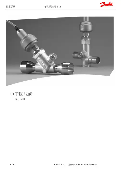
丹佛斯TE系列膨胀阀
- 格式:doc
- 大小:211.00 KB
- 文档页数:5
MAKING MODERN LIVING POSSIBLE热力膨胀阀TE5-TE55型引言 4特点 4技术数据 5过热度 5标识 5设计/功能 6订货 6 R134a 9 R404A/R507 11 R407C 15 R22 17尺寸及重量 21引言特点热力膨胀阀用于调节蒸发器中的液体制冷剂的供给量。
该供给量是通过制冷剂的过热度进行控制的。
可互换的热力感温原件使用丹佛斯著名的激光焊接技术,使用寿命更长。
新设计的流口组件冷量范围更加连续完整,应用范围更加广泛。
■蒸发温度范围大N系列-40℃至+10℃B系列-60℃至-25℃■可互换流口组件■不锈钢制的执行元件,毛细管和感温包■冷量范围宽■可提供MOP功能■精确的感温包充注■专利的感温包卡带设计■ MWP(最高工作压力)28 bar■冷量范围宽,冷量间隙和重叠小■ TE55具有平衡流口设计技术数据过热度■ 最高温度安装后,感温包承受的温度: 100℃未安装前阀的温度: 70℃■ 最低温度: -60℃■ 最高试验压力: 32 bar ■ 最高工作压力: 28 barMOP=最高运行压力SS :静态过热度OS :开启过热度SH :总过热度(SS + OS )Q nom :名义制冷量Q max : 最大制冷量举例静态过热度 SS = 4 K 开启过热度 OS = 4 K 总过热度 SH = 4 + 4 = 8 K静态过热度SS 可以使用调节杆来调节。
标准工厂过热度设置为4K 。
开启过热度OS = 4K 是阀开启至名义制冷量的开度时所对应的过热度。
使用B 系列流口组件时,如有必要,请确认运行工况下的过热度和重新调整过热度设置。
标识热力元件上贴有标签(在膜片装置的上方),上面标明阀所适用的制冷剂种类,例如:X = R22N = R134aS = R404A/R507Z = R407C同时,标签也标明了阀的型号、蒸发温度范围、MOP点,制冷剂以及最高试验压力和最高工作压力。
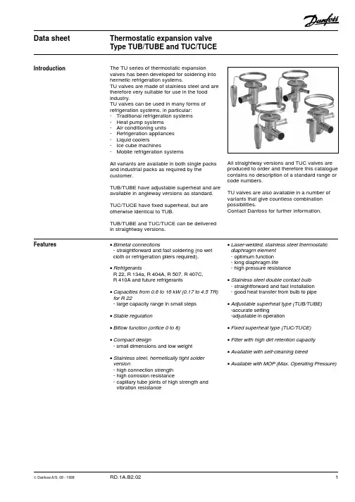
Data sheetThermostatic expansion valve Type TUB/TUBE and TUC/TUCEIntroductionThe TU series of thermostatic expansion valves has been developed for soldering into hermetic refrigeration systems.TU valves are made of stainless steel and are therefore very suitable for use in the food industry.TU valves can be used in many forms of refrigeration systems, in particular:-Traditional refrigeration systems -Heat pump systems -Air conditioning units -Refrigeration appliances -Liquid coolers-Ice cube machines-Mobile refrigeration systemsAll variants are available in both single packs and industrial packs as required by the customer.TUB/TUBE have adjustable superheat and are available in angleway versions as standard.TUC/TUCE have fixed superheat, but are otherwise identical to TUB.TUB/TUBE and TUC/TUCE can be delivered in straightway versions.All straightway versions and TUC valves are produced to order and therefore this catalogue contains no description of a standard range or code numbers.TU valves are also available in a number of variants that give countless combination possibilities.Contact Danfoss for further information.Features·Bimetal connections-straightforward and fast soldering (no wet cloth or refrigeration pliers required).·RefrigerantsR 22, R 134a, R 404A, R 507, R 407C,R 410A and future refrigerants·Capacities from 0.6 to 16 kW (0.17 to 4.5 TR)for R 22-large capacity range in small steps ·Stable regulation·Biflow function (orifice 0 to 8)·Compact design- small dimensions and low weight ·Stainless steel, hermetically tight solder version-high connection strength -high corrosion resistance-capillary tube joints of high strength and vibration resistance·Laser-welded, stainless steel thermostatic diaphragm element -optimum function -long diaphragm life-high pressure resistance·Stainless steel double contact bulb -straightforward and fast installation -good heat transfer from bulb to pipe ·Adjustable superheat type (TUB/TUBE)-accurate setting-adjustable in operation·Fixed superheat type (TUC/TUCE)·Filter with high dirt retention capacity ·Available with self-cleaning bleed·Available with MOP (Max. Operating Pressure)Data sheet Thermostatic expansion valve, type TUB/TUBE and TUC/TUCEMax. bulb temperature100°C Max. valve body temperature 120°C,short-lived peak 150°CPermissible working pressure (excl. R 410A)PB =28 bar Max. working pressure, R 410A PB =42.5 bar Max. test pressure (excl. R 410A)p’ =36 bar Max. test pressure, R 410A p’ =47 barBiflow operationWith flow in the opposite direction, the rated capacity is reduced by up to 15%.TUBE with orifice 9, TUB and valves with MOP charges cannot be used for biflow operation.Technical dataMOP-pointsRange N Range NM Range B Refrigerant -40 ® +10°C -40 ® -5°C -60 ® -25°C MOP point for evaporating temperature t e and evaporating pressure p e 1)t e = +15°C/+60°F t e = 0°C/+32°F t e = -20°C/-4°F R 22p e = 100 psig/6.9 bar p e = 60 psig/4.0 bar p e = 20 psig/1.5 bar R 134ap e = 55 psig/3.9 bar p e = 30 psig/1.9 bar R 404A / R 507p e = 120 psig/8.4 bar p e = 75 psig/5.0 bar p e = 30 psig/2.0 bar R 407C p e = 95 psig/6.6 bar p e = 50 psig/3.6 bar p e =15 psig/1.1 bar R 410Ap e = 165 psig/11.5 bar p e = 100 psig/7.0 bar p e =45 psig/3.0 barTo avoid charge migration when MOP valves are used, the bulb temperature must be lower than the thermostatic element temperature.MOP valves1)p e in bar gaugeFor further information,please contact Danfoss.Capillary tube length: 1.5 m Bleed: 15%Connections:Inlet Orifice 0 ® 63/8 in./10 mm Orifice 7 ® 91/4 in./6 mm Straightway only1/2 in./12 mm Outlet3/8 in./10 mm Straightway only5/8 in./16 mmCapacity, orifice variants:In addition to the standard range, valves with orifice 0 are available for R 134a, R 404A and R 507.Variant rangeIn addition to the standard range, TUB/TUBE and TUC/TUCE valves are also available in these variants and variant combinations:Straightway versions Range N -40 ®+10°C MOP +15°C Range NM -40 ®-5°C MOP 0°C Range B -60 ®-25°C Range B–60 ®-25°CMOP -20°CStatic superheat (SS):2 K,3 K,4 K, or 6 K (applies to TUB/TUBE and TUC/TUCE – see fig. 5)Capillary tube length: 0.8 m Connections:Inlet Orifice 0 ® 61/4 in./6 mm Orifice 7 ® 93/8 in./10 mm Outlet1/2 in./12 mmStandard range Versions available in the standard range:Range N : -40 to +10°C without MOP Static superheat (SS):R 22, R 134a, R 404A, R 407C, R 410A = 5 K R 507 = 6.4 KData sheet Thermostatic expansion valve, type TUB/TUBE and TUC/TUCERange N = -40 ® +10 °CR 22, R 134a, R 404A/R 507Ordering AnglewaySupplied with bulb strap Standard valve rangeValves with inch connections have 1/4 in. pressure equalisation.Valves with mm connections have 6 mm pressure equalisation.1)Rated capacity Q nom. is based on:Evaporating temperature t e = +5°CCondensing temperature t c = +32°CRefrigerant liquid temperature t l = +28°COpening superheat OS = 4 K2)TUBE with orifice 9 and TUB (internal pressure equalisation)cannot be used for biflow operation.Refri-TypeRated Orifice Pres-Connection gerantcapacity no.2)sure Inlet ´ OutletQ nom. 1)equali-kW TR sation inch Code no.mm Code no.TUB 0.60.170int.1/4 ´ 1/2068U20566 ´ 12068U2036TUB 0.90.251int.1/4 ´ 1/2068U20576 ´ 12068U2037TUB 1.30.362int.1/4 ´ 1/2068U20586 ´ 12068U2038TUB 1.80.503int.1/4 ´ 1/2068U20596 ´ 12068U2039TUB 2.60.754int.1/4 ´ 1/2068U20606 ´ 12068U2040TUB 3.5 1.005int.1/4 ´ 1/2068U20616 ´ 12068U2041TUB 5.3 1.506int.1/4 ´ 1/2068U20626 ´ 12068U2042TUB 7.0 2.007int.3/8 ´ 1/2068U206310 ´ 12068U2043TUB 11.0 3.008int.3/8 ´ 1/2068U206410 ´ 12068U2044TUB 16.0 4.509int.3/8 ´ 1/2068U206510 ´ 12068U2045R 22TUBE 0.60.170ext.1/4 ´ 1/2068U20666 ´ 12068U2046TUBE 0.90.251ext.1/4 ´ 1/2068U20676 ´ 12068U2047TUBE 1.30.362ext.1/4 ´ 1/2068U20686 ´ 12068U2048TUBE 1.80.503ext.1/4 ´ 1/2068U20696 ´ 12068U2049TUBE 2.60.754ext.1/4 ´ 1/2068U20706 ´ 12068U2050TUBE 3.5 1.005ext.1/4 ´ 1/2068U20716 ´ 12068U2051TUBE 5.3 1.506ext.1/4 ´ 1/2068U20726 ´ 12068U2052TUBE 7.0 2.007ext.3/8 ´ 1/2068U207310 ´ 12068U2053TUBE 11.0 3.008ext.3/8 ´ 1/2068U207410 ´ 12068U2054TUBE 16.0 4.509ext.3/8 ´ 1/2068U207510 ´ 12068U2055TUB 0.70.191int.1/4 ´ 1/2068U20276 ´ 12068U2000TUB 1.00.282int.1/4 ´ 1/2068U20286 ´ 12068U2001TUB 1.40.393int.1/4 ´ 1/2068U20296 ´ 12068U2002TUB 2.10.594int.1/4 ´ 1/2068U20306 ´ 12068U2003TUB 2.70.785int.1/4 ´ 1/2068U20316 ´ 12068U2004TUB 4.1 1.206int.1/4 ´ 1/2068U20326 ´ 12068U2005TUB 5.5 1.607int.3/8 ´ 1/2068U203310 ´ 12068U2006TUB 8.2 2.308int.3/8 ´ 1/2068U203410 ´ 12068U2007TUB 12.0 3.509int.3/8 ´ 1/2068U203510 ´ 12068U2008R 134aTUBE 0.70.191ext.1/4 ´ 1/2068U20186 ´ 12068U2009TUBE 1.00.282ext.1/4 ´ 1/2068U20196 ´ 12068U2010TUBE 1.40.393ext.1/4 ´ 1/2068U20206 ´ 12068U2011TUBE 2.10.594ext.1/4 ´ 1/2068U20216 ´ 12068U2012TUBE 2.70.785ext.1/4 ´ 1/2068U20226 ´ 12068U2013TUBE 4.1 1.206ext.1/4 ´ 1/2068U20236 ´ 12068U2014TUBE 5.5 1.607ext.3/8 ´ 1/2068U202410 ´ 12068U2015TUBE 8.2 2.308ext.3/8 ´ 1/2068U202510 ´ 12068U2016TUBE 12.0 3.509ext.3/8 ´ 1/2068U202610 ´ 12068U2017TUB 0.70.191int.1/4 ´ 1/2068U20946 ´ 12068U2076TUB 1.00.282int.1/4 ´ 1/2068U20956 ´ 12068U2077TUB 1.40.393int.1/4 ´ 1 /2068U20966 ´ 12068U2078TUB 2.10.604int.1/4 ´ 1/2068U20976 ´ 12068U2079TUB 2.80.795int.1/4 ´ 1/2068U20986 ´ 12068U2080TUB 4.2 1.206int.1/4 ´ 1/2068U20996 ´ 12068U2081TUB 5.6 1.607int.3/8 ´ 1/2068U210010 ´ 12068U2082TUB 8.4 2.408int.3/8 ´ 1/2068U210110 ´ 12068U2083TUB 12.0 3.509int. 3/8 ´ 1/2068U210210 ´ 12068U2084R 404A TUBE 0.70.191ext.1/4 ´ 1/2068U21036 ´ 12068U2085R 507TUBE 1.00.282ext.1/4 ´ 1/2068U21046 ´ 12068U2086TUBE 1.40.393ext.1/4 ´ 1/2068U21056 ´ 12068U2087TUBE 2.10.604ext.1/4 ´ 1/2068U21066 ´ 12068U2088TUBE 2.80.795ext.1/4 ´ 1/2068U21076 ´ 12068U2089TUBE 4.2 1.206ext.1/4 ´ 1/2068U21086 ´ 12068U2090TUBE 5.6 1.607ext.3/8 ´ 1/2068U210910 ´ 12068U2091TUBE 8.4 2.408ext.3/8 ´ 1/2068U211010 ´ 12068U2092TUBE12.03.509ext.3/8 ´ 1/2068U211110 ´ 12068U2093Data sheet Thermostatic expansion valve, type TUB/TUBE and TUC/TUCER 407C, R 410ARange N = -40 ® +10 °CRefri-TypeRated Orifice Pres-Connection gerantcapacity no.2)sure Inlet ´ OutletQ nom. 1)equali-kW TR sation inch Code no.mm Code no.TUB 0.630.180int.1/4 ´ 1/2068U1920 6 ´ 12068U1900TUB 0.920.261int.1/4 ´ 1/2068U1921 6 ´ 12068U1901TUB 1.40.382int.1/4 ´ 1/2068U1922 6 ´ 12068U1902TUB 1.90.533int.1/4 ´ 1/2068U1923 6 ´ 12068U1903TUB 2.80.804int.1/4 ´ 1/2068U1924 6 ´ 12068U1904TUB 3.8 1.105int.1/4 ´ 1/2068U1925 6 ´ 12068U1905TUB 5.7 1.606int.1/4 ´ 1/2068U1926 6 ´ 12068U1906TUB 7.5 2.107int.3/8 ´ 1/2068U192710 ´ 12068U1907TUB 11.0 3.208int.3/8 ´ 1/2068U192810 ´ 12068U1908TUB 17.0 4.809int.3/8 ´ 1/2068U192910 ´ 12068U1909R 407CTUBE 0.630.180ext.1/4 ´ 1/2068U1930 6 ´ 12068U1910TUBE 0.920.261ext.1/4 ´ 1/2068U1931 6 ´ 12068U1911TUBE 1.40.382ext.1/4 ´ 1/2068U1932 6 ´ 12068U1912TUBE 1.90.533ext.1/4 ´ 1/2068U1933 6 ´ 12068U1913TUBE 2.80.804ext.1/4 ´ 1/2068U1934 6 ´ 12068U1914TUBE 3.8 1.105ext.1/4 ´ 1/2068U1935 6 ´ 12068U1915TUBE 5.7 1.606ext.1/4 ´ 1/2068U1936 6 ´ 12068U1916TUBE 7.5 2.107ext.3/8 ´ 1/2068U193710 ´ 12068U1917TUBE 11.0 3.208ext.3/8 ´ 1/2068U193810 ´ 12068U1918TUBE 17.0 4.809ext.3/8 ´ 1/2068U193910 ´ 12068U1919TUB 0.820.230int.1/4 ´ 1/2068U1798 6 ´ 12068U1796TUB 1.30.41int.1/4 ´ 1/2068U1958 6 ´ 12068U1940TUB 2.10.62int.1/4 ´ 1/2068U1959 6 ´ 12068U1941TUB 2.90.83int.1/4 ´ 1/2068U1960 6 ´ 12068U1942TUB 4.5 1.34int.1/4 ´ 1/2068U1961 6 ´ 12068U1943TUB 5.9 1.75int.1/4 ´ 1/2068U1962 6 ´ 12068U1944TUB 9.0 2.56int.1/4 ´ 1/2068U1963 6 ´ 12068U1945TUB 12.0 3.47int.3/8 ´ 1/2068U196410 ´ 12068U1946TUB 18.0 5.08int.3/8 ´ 1/2068U196510 ´ 12068U1947TUB 26.07.59int.3/8 ´ 1/2068U196610 ´ 12068U1948 R 410ATUBE 0.820.230ext.1/4 ´ 1/2068U1799 6 ´ 12068U1797TUBE 1.30.41ext.1/4 ´ 1/2068U1967 6 ´ 12068U1949TUBE 2.10.62ext.1/4 ´ 1/2068U1968 6 ´ 12068U1950TUBE 2.90.83ext.1/4 ´ 1/2068U1969 6 ´ 12068U1951TUBE 4.5 1.34ext.1/4 ´ 1/2068U1970 6 ´ 12068U1952TUBE 5.9 1.75ext.1/4 ´ 1/2068U1971 6 ´ 12068U1953TUBE 9.0 2.56ext.1/4 ´ 1/2068U1972 6 ´ 12068U1954TUBE 12.0 3.47ext.3/8 ´ 1/2068U197310 ´ 12068U1955TUBE 18.0 5.08ext.3/8 ´ 1/2068U197410 ´ 12068U1956TUBE26.07.59ext.3/8 ´ 1/2068U197510 ´ 12068U1957Valves with inch connections have 1/4 in. pressure equalisation.Valves with mm connections have 6 mm pressure equalisation.1)Rated capacity Q nom. is based on:Evaporating temperature t e = +5°CCondensing temperature t c = +32°CRefrigerant liquid temperature t l = +28°COpening superheat OS = 4 K2)TUBE with orifice 9 and TUB (internal pressure equalisation)cannot be used for biflow operation.Ordering AnglewaySupplied with bulb strap Standard valve rangeData sheet Thermostatic expansion valve, type TUB/TUBE and TUC/TUCER 22CapacityPressure drop across valve D p bar 246810121416Evaporating temperature 0°C 0.400.500.560.600.630.650.670.670.550.710.800.860.910.930.950.960.73 1.0 1.1 1.2 1.3 1.3 1.4 1.41.0 1.3 1.5 1.7 1.8 1.8 1.9 1.91.5 2.0 2.3 2.5 2.7 2.8 2.8 2.82.0 2.7 3.1 3.4 3.5 3.7 3.8 3.83.1 4.0 4.6 5.0 5.3 5.5 5.7 5.84.1 5.4 6.2 6.77.17.47.67.76.18.09.210.110.611.011.311.59.112.113.815.015.916.416.817.1Evaporating temperature -20°C 0.400.450.480.500.520.530.530.510.570.620.650.670.680.690.610.700.760.790.820.840.850.9 1.0 1.1 1.1 1.2 1.2 1.21.3 1.5 1.6 1.6 1.7 1.7 1.81.7 1.9 2.1 2.2 2.3 2.3 2.32.5 2.9 3.1 3.3 3.4 3.5 3.53.4 3.9 4.2 4.4 4.5 4.6 4.75.1 5.8 6.3 6.6 6.87.07.17.68.69.39.710.110.310.4Evaporating temperature -40°C 0.310.330.340.350.360.360.330.360.380.390.390.400.390.420.440.450.460.460.550.590.610.630.640.650.800.860.900.920.940.951.1 1.2 1.2 1.2 1.3 1.31.6 1.7 1.8 1.8 1.9 1.92.1 2.3 2.4 2.5 2.5 2.53.2 3.5 3.6 3.7 3.8 3.84.7 5.1 5.3 5.55.55.6Evaporating temperature -30°C 00.340.380.400.420.440.440.4510.390.450.480.510.520.530.5420.470.530.570.600.620.630.6330.660.740.800.840.870.880.894 1.0 1.1 1.2 1.2 1.3 1.3 1.35 1.3 1.5 1.6 1.7 1.7 1.7 1.86 1.9 2.2 2.4 2.5 2.5 2.6 2.67 2.6 2.9 3.2 3.3 3.4 3.5 3.58 3.9 4.4 4.8 5.0 5.1 5.2 5.395.76.57.07.37.57.77.7TypeOrifice Pressure drop across valve D p bar no.246810121416Evaporating temperature +10°C 00.420.530.600.650.680.700.710.7210.610.790.89 1.0 1.0 1.0 1.1 1.120.9 1.2 1.3 1.5 1.6 1.6 1.7 1.73 1.2 1.6 1.8 2.0 2.1 2.2 2.3 2.34 1.8 2.4 2.8 3.1 3.2 3.4 3.5 3.55 2.4 3.2 3.7 4.1 4.3 4.5 4.6 4.76 3.7 4.9 5.6 6.1 6.5 6.7 6.97.17 4.9 6.57.58.28.69.09.29.487.39.611.212.212.913.413.713.9910.914.516.718.219.320.020.520.9D t sub4 K10 K 15 K 20 K 25 K 30 K 35 K 40 K 45 K 50 K R 221.001.061.111.151.21.251.31.351.391.44Correction factor for subcooling D t subEvaporating temperature -10°C 00.360.460.510.550.570.590.600.6110.470.620.700.750.790.810.820.8320.600.780.89 1.0 1.0 1.1 1.1 1.130.8 1.1 1.3 1.4 1.4 1.5 1.5 1.54 1.2 1.6 1.9 2.0 2.1 2.2 2.2 2.35 1.7 2.2 2.5 2.7 2.8 2.9 3.0 3.06 2.5 3.2 3.7 4.0 4.3 4.4 4.5 4.67 3.3 4.3 5.0 5.4 5.7 5.9 6.0 6.18 5.0 6.57.58.18.58.89.09.197.49.711.112.012.613.113.313.5Capacity in kW for range N = -40 ® +10°C and opening superheat OS = 4 KTUTUTUNote:Insufficient subcooling can produce flash gas.Correction for subcooling D t subThe evaporator capacity used must be corrected if subcooling deviates from 4 K.The corrected capacity can be obtained by dividing the evaporator capacity by the correction factor given below.Since the expansion valve capacity must be equal to or slightly more than the corrected evaporator capacity of 2.7 kW, a TUB/TUBE with orifice 5 and a table capacity of 2.8 kW would be a suitable choice.Refrigerant = R 22Evaporating temperature t e = -10°C Pressure drop in valve D p = 10 bar Subcooling D t sub = 15 K Evaporator capacity = 3 kW Correction value (table) = 1.11The corrected evaporator capacity thus becomes 3 divided by 1.11 = 2.7 kWSelection exampleData sheet Thermostatic expansion valve, type TUB/TUBE and TUC/TUCECapacity (continued)Evaporating temperature -40°C 0.180.190.200.200.200.190.210.210.210.210.220.240.250.250.250.310.340.350.350.350.450.490.500.510.510.610.660.680.680.680.900.97 1.0 1.0 1.01.2 1.3 1.4 1.4 1.41.8 2.0 2.1 2.1 2.12.72.93.0 3.0 3.0Evaporating temperature -20°C 0.310.340.350.350.350.390.430.440.450.450.470.510.530.540.540.650.720.750.760.760.96 1.05 1.10 1.12 1.11.3 1.4 1.5 1.5 1.51.9 2.1 2.2 2.2 2.22.6 2.8 3.0 3.0 3.03.9 4.3 4.4 4.5 4.55.7 6.2 6.5 6.6 6.6Evaporating temperature -10°C 00.310.370.400.420.430.4310.410.510.550.580.580.5820.510.640.700.740.750.7630.710.890.98 1.0 1.1 1.14 1.1 1.3 1.5 1.5 1.6 1.65 1.4 1.8 2.0 2.1 2.1 2.16 2.1 2.7 2.9 3.1 3.1 3.27 2.8 3.5 3.9 4.1 4.2 4.28 4.3 5.3 5.9 6.2 6.3 6.39 6.37.98.79.19.39.3TypeOrifice Pressure drop across valve D p bar no.246810121416Evaporating temperature +10°C 00.380.460.500.530.540.5410.570.690.760.790.810.8120.82 1.1 1.2 1.2 1.3 1.33 1.1 1.4 1.6 1.7 1.8 1.84 1.7 2.2 2.5 2.6 2.7 2.75 2.3 2.9 3.3 3.5 3.6 3.66 3.4 4.4 4.9 5.2 5.4 5.57 4.6 5.9 6.67.07.27.28 6.88.79.810.310.610.8910.213.114.615.515.916.0D t sub4 K10 K 15 K 20 K 25 K 30 K 35 K 40 K 45 K 50 K R 134a1.001.081.131.191.251.311.371.421.481.54Correction factor for subcooling D t subPressure drop across valve D p bar 246810121416Evaporating temperature 0°C 0.350.420.460.480.490.490.500.610.660.690.700.710.660.840.930.98 1.0 1.00.92 1.2 1.3 1.4 1.4 1.41.4 1.8 1.9 2.0 2.1 2.11.8 2.3 2.6 2.7 2.8 2.82.8 3.5 3.9 4.1 4.2 4.33.7 4.7 5.2 5.5 5.6 5.75.57.07.88.28.48.58.310.411.512.212.412.5Evaporating temperature -30°C 00.250.270.280.280.2810.280.300.320.320.3220.320.350.370.370.3730.460.500.520.530.5240.670.730.760.770.7650.900.98 1.02 1.03 1.06 1.3 1.5 1.5 1.5 1.57 1.8 2.0 2.0 2.1 2.18 2.7 3.0 3.1 3.1 3.194.04.3 4.5 4.5 4.5Capacity in kW for range N = -40 ® +10°C and opening superheat OS = 4 KR 134aTUTUTUCorrection for subcooling D t subThe evaporator capacity used must be corrected if subcooling deviates from 4 K.The corrected capacity can be obtained by dividing the evaporator capacity by the correction factor given below.Note:Insufficient subcooling can produce flash gas.Data sheet Thermostatic expansion valve, type TUB/TUBE and TUC/TUCECapacity (continued)Pressure drop across valve D p bar246810121416Evaporating temperature 0°C 0.310.390.420.440.440.440.430.420.440.560.610.640.640.640.630.610.600.770.870.920.940.940.930.900.83 1.1 1.2 1.3 1.3 1.5 1.3 1.31.3 1.6 1.8 1.9 2.0 2.0 1.9 1.91.7 2.2 2.4 2.6 2.6 2.6 2.6 2.52.5 3.2 3.6 3.8 3.9 3.9 3.9 3.83.4 4.3 4.8 5.1 5.2 5.3 5.2 5.05.0 6.57.27.67.87.87.77.57.59.610.811.411.711.711.511.2TypeOrifice Pressure drop across valve D p bar no.246810121416Evaporating temperature +10°C 00.320.400.440.460.460.460.450.4410.470.600.680.690.700.700.680.6620.700.91 1.0 1.1 1.1 1.1 1.1 1.130.96 1.2 1.4 1.5 1.5 1.5 1.5 1.54 1.5 1.9 2.1 2.3 2.3 2.3 2.3 2.25 2.0 2.5 2.8 3.0 3.1 3.1 3.1 3.06 2.9 3.8 4.3 4.5 4.7 4.7 4.6 4.57 3.9 5.1 5.7 6.0 6.2 6.2 6.1 6.08 5.87.58.49.09.29.29.18.998.811.312.713.513.813.913.713.39Evaporating temperature -10°C 00.290.360.390.400.410.410.400.3910.390.500.540.570.570.570.560.5420.500.640.710.750.760.760.750.7330.700.890.99 1.0 1.1 1.1 1.1 1.04 1.0 1.3 1.5 1.6 1.6 1.6 1.6 1.55 1.4 1.8 2.0 2.1 2.1 2.1 2.1 2.06 2.1 2.7 3.0 3.1 3.2 3.2 3.1 3.17 2.8 3.6 4.0 4.2 4.3 4.3 4.2 4.18 4.2 5.3 5.9 6.3 6.4 6.4 6.3 6.19 6.27.98.89.39.59.59.39.0Evaporating temperature -20°C 0.320.350.360.360.360.350.340.410.460.480.480.480.470.450.510.560.590.600.600.590.570.710.790.830.840.840.820.801.1 1.2 1.2 1.2 1.2 1.2 1.21.4 1.6 1.6 1.7 1.7 1.6 1.62.1 2.3 2.4 2.5 2.5 2.4 2.42.8 3.1 3.3 3.3 3.3 3.3 3.24.3 4.7 4.9 5.0 5.0 4.9 4.86.36.97.37.47.47.27.0Evaporating temperature -30°C 00.30.310.310.310.30.2910.360.380.380.380.370.3620.430.450.450.450.440.4330.600.630.640.630.620.6040.890.930.940.930.910.885 1.2 1.2 1.3 1.2 1.2 1.26 1.8 1.9 1.9 1.9 1.8 1.87 2.4 2.5 2.5 2.5 2.4 2.48 3.6 3.7 3.8 3.8 3.7 3.695.3 5.5 5.5 5.55.45.2Evaporating temperature -40°C 0.240.250.250.250.240.230.270.280.280.280.270.260.320.330.330.330.320.310.450.460.470.460.450.430.650.680.680.670.660.630.880.910.910.900.880.851.3 1.4 1.4 1.3 1.3 1.31.8 1.8 1.8 1.8 1.8 1.72.6 2.7 2.8 2.7 2.7 2.63.9 4.0 4.0 4.03.93.7Capacity in kW for range N = -40 ® +10°C and opening superheat OS = 4 KR 404A/R507D t sub4 K 10 K 15 K 20 K 25 K 30 K 35 K 40 K 45 K 50 K R 404A/R 5071.001.11.21.291.371.46 1.54 1.63 1.7 1.78Correction factor for subcooling D t subTUTUTUCorrection for subcooling D t subThe evaporator capacity used must be corrected if subcooling deviates from 4 K.The corrected capacity can be obtained by dividing the evaporator capacity by the correction factor given below.Note:Insufficient subcooling can produce flash gas.Capacity (continued)Evaporating temperature -20°C 0.330.400.440.470.480.490.490.490.390.500.560.600.620.630.630.630.470.600.680.720.750.760.770.760.660.840.95 1.0 1.1 1.1 1.1 1.10.98 1.3 1.4 1.5 1.6 1.6 1.6 1.61.3 1.7 1.9 2.0 2.1 2.1 2.1 2.11.9 2.5 2.8 3.0 3.1 3.2 3.2 3.22.6 3.3 3.7 4.0 4.1 4.2 4.2 4.23.9 5.0 5.7 6.0 6.2 6.4 6.4 6.45.87.48.38.99.29.39.49.3Evaporating temperature -10°C 00.370.460.510.540.550.560.570.5610.480.620.700.740.760.770.770.7720.600.780.880.940.98 1.00 1.01 1.0130.84 1.1 1.2 1.3 1.4 1.4 1.4 1.44 1.3 1.6 1.8 2.0 2.0 2.1 2.1 2.15 1.7 2.2 2.4 2.6 2.7 2.8 2.8 2.86 2.5 3.2 3.7 3.9 4.1 4.2 4.2 4.27 3.4 4.3 4.9 5.2 5.5 5.6 5.6 5.68 5.0 6.57.47.98.28.48.48.497.59.610.911.612.112.312.412.4Pressure drop across valve D p bar246810121416Evaporating temperature 0°C 0.410.510.560.600.620.630.630.630.560.730.810.860.890.900.910.900.8 1.0 1.1 1.2 1.2 1.3 1.3 1.31.0 1.4 1.5 1.7 1.7 1.8 1.8 1.81.6 2.1 2.3 2.5 2.6 2.7 2.7 2.72.1 2.7 3.1 3.3 3.5 3.5 3.6 3.63.1 4.1 4.6 5.0 5.2 5.3 5.4 5.44.2 5.4 6.2 6.7 6.97.17.27.26.38.29.39.910.410.610.710.79.312.213.814.815.415.815.915.9TypeOrifice Pressure drop across valve D p bar no.246810121416Evaporating temperature +10°C 00.430.540.600.640.670.680.680.6810.630.810.900.960.99 1.01 1.02 1.0120.90 1.2 1.4 1.5 1.5 1.6 1.6 1.63 1.2 1.6 1.9 2.0 2.1 2.2 2.2 2.24 1.9 2.5 2.8 3.1 3.2 3.3 3.3 3.35 2.5 3.3 3.8 4.1 4.2 4.4 4.4 4.46 3.8 5.0 5.7 6.1 6.4 6.6 6.7 6.77 5.0 6.67.68.28.68.88.98.987.59.911.212.212.713.013.213.2911.314.816.918.219.019.519.719.7D t sub4 K10 K 15 K 20 K 25 K 30 K 35 K 40 K 45 K 50 K R 407C1.001.081.141.211.271.331.391.451.511.57Correction factor for subcooling D t subEvaporating temperature -40°C 0.290.310.320.320.320.310.310.330.340.340.350.340.360.380.400.400.400.400.510.540.560.560.560.560.750.790.810.820.820.821.0 1.1 1.1 1.1 1.1 1.11.5 1.6 1.6 1.6 1.6 1.62.0 2.1 2.2 2.2 2.2 2.23.0 3.2 3.3 3.3 3.3 3.34.4 4.7 4.8 4.94.9 4.8Evaporating temperature -30°C 00.260.290.310.320.320.320.3110.380.430.450.470.480.480.4720.450.500.530.550.560.560.5630.630.710.750.780.790.790.7940.93 1.0 1.1 1.1 1.2 1.2 1.25 1.3 1.4 1.5 1.5 1.6 1.6 1.56 1.9 2.1 2.2 2.3 2.3 2.3 2.37 2.5 2.8 3.0 3.1 3.1 3.1 3.18 3.8 4.2 4.5 4.6 4.7 4.7 4.79 5.5 6.2 6.5 6.7 6.86.9 6.8Capacity in kW for range N = -40 ® +10°C and opening superheat OS = 4 KR 407CTUTUTUCorrection for subcooling D t subThe evaporator capacity used must be corrected if subcooling deviates from 4 K.The corrected capacity can be obtained by dividing the evaporator capacity by the correction factor given below.Note:Insufficient subcooling can produce flash gas.Capacity (continued)R 410ATypeOrifice Pressure drop across valve D p bar Pressure drop across valve D p bar no.36912151821243691215182124Evaporating temperature +10°CEvaporating temperature 0°C Evaporating temperature -10°C Evaporating temperature -20°C Capacity in kW for range N = -40 to +10°C and opening superheat OS = 4 KEvaporating temperature -30°C Evaporating temperature -40°C D t sub4 K10 K15 K20 K25 K30 K 35 K 40 K 45 K 50 KR 410A1.00 1.08 1.15 1.21 1.27 1.33 1.39 1.45 1.50 1.56Correction factor for subcooling D t sub00.560.720.800.850.870.880.870.850.560.700.780.830.850.860.850.8410.89 1.13 1.26 1.30 1.37 1.38 1.36 1.330.84 1.06 1.18 1.24 1.29 1.30 1.29 1.272 1.45 1.90 2.2 2.3 2.4 2.5 2.4 2.4 1.25 1.64 1.86 1.99 2.1 2.1 2.1 2.13 1.98 2.6 3.0 3.2 3.3 3.3 3.3 3.3 1.72 2.3 2.6 2.7 2.9 2.9 2.9 2.94 3.1 4.1 4.6 4.9 5.1 5.2 5.1 5.0 2.6 3.5 3.9 4.2 4.3 4.4 4.4 4.3TU5 4.1 5.3 6.1 6.5 6.7 6.8 6.8 6.7 3.5 4.6 5.2 5.6 5.8 5.9 5.8 5.86 6.28.19.29.910.310.510.410.2 5.3 6.97.98.48.78.98.98.878.210.712.713.113.613.813.813.57.09.210.411.111.611.811.811.6812.115.818.019.320.020.320.219.910.413.715.516.617.217.517.517.2918.324.027.229.130.230.630.529.915.720.523.324.925.826.226.225.700.530.670.740.780.800.810.810.790.600.670.700.720.730.730.7210.760.96 1.07 1.13 1.16 1.17 1.17 1.150.830.920.97 1.00 1.01 1.000.992 1.04 1.35 1.52 1.63 1.69 1.72 1.72 1.70 1.06 1.20 1.28 1.32 1.34 1.34 1.333 1.44 1.86 2.1 2.3 2.3 2.4 2.4 2.4 1.48 1.67 1.78 1.84 1.87 1.87 1.854 2.2 2.8 3.2 3.4 3.5 3.6 3.6 3.5 2.2 2.5 2.7 2.7 2.8 2.8 2.8TU5 2.9 3.7 4.2 4.5 4.7 4.8 4.8 4.8 3.0 3.3 3.5 3.7 3.7 3.7 3.76 4.3 5.6 6.4 6.87.17.27.27.1 4.4 5.0 5.3 5.5 5.6 5.6 5.57 5.87.58.59.19.49.69.69.5 5.9 6.67.17.47.57.57.488.611.212.713.614.114.314.314.18.910.010.711.011.211.211.1912.916.819.020.321.021.321.321.013.214.815.816.416.616.616.400.520.580.610.630.630.630.620.480.500.520.520.520.5110.660.740.790.820.820.820.810.560.590.610.620.620.6120.810.900.96 1.00 1.01 1.01 1.000.660.700.720.730.730.723 1.13 1.27 1.35 1.40 1.41 1.41 1.400.930.98 1.02 1.03 1.03 1.014 1.67 1.87 2.0 2.1 2.1 2.1 2.1 1.36 1.45 1.49 1.51 1.50 1.48TU5 2.2 2.5 2.7 2.8 2.8 2.8 2.8 1.82 1.9 2.0 2.0 2.0 2.06 3.3 3.7 4.0 4.1 4.2 4.2 4.1 2.7 2.9 3.0 3.0 3.0 3.07 4.5 5.0 5.4 5.5 5.6 5.6 5.5 3.6 3.9 4.0 4.0 4.0 4.08 6.77.68.08.38.48.48.3 5.5 5.8 6.0 6.1 6.1 6.099.911.111.812.212.412.412.28.18.68.88.98.98.8Correction for subcooling D t subThe evaporator capacity used must be corrected if subcooling deviates from 4 K.The corrected capacity can be obtained by dividing the evaporator capacity by the correction factor given below.Note:Insufficient subcooling can produce flash gas.。
MAKING MODERN LIVING POSSIBLEDanfoss A/S (AC-MCI sw) 2013-10 DKRCC.PD.VD1.D3.02 / 520H7937Data sheetElectronic expansion valves Type ETS 6The range of electronic expansion valves are based on many years of experience.ETS 6 secure reliability and provide a precise solutions for ex p ansion and flow control in a wide range of refrigeration and air conditioning systems.Compact and lightweight. The current range is available with a wide capacity range, and can be used with all common fluorinated refrigerants. Bi-flow operation is also possible for heat pump systems.The valve operation is by means of a uni-polar motor, which can be controlled by a number of controllers from Danfoss or third party vendors.With an EKD 316 and EIM 336 (current drivers) and an AKS sensor, an accuracy better than +/-0.5 K can be obtained.Please contact Danfoss for more details.FeaturesOptimized energy efficiency of the system. Precision flow control with high resolution. Compact and lightweight. Energy saving design.Proven know-how and high reliability. Wide range for all common refrigerants. Bi-flow for heat pump applications.2DKRCC.PD.VD1.D3.02 / 520H7937Danfoss A/S (AC-MCI sw) 2013-10Data sheetElectronic Expansion Valves, type ETS 6Design/functionThe ETS 6 electronic expansion valves open and close to regulate refrigerant flow by means of a screw, whose rotating motion is transformed into linear motion. This occurs by the rotation of a magnet-needle valve assembly whichmoves when electrical signals are applied to the surrounding coil.Within the coil structure, there are different winding configurations, and the polarities arechanged by the electrical signals applied. By application of the appropriate combination of signals, in the form of pulses, the coil forces the rotor of the valve to move in a stepwise fashion.Application of multiple pulses will make the valve mechanism to move through a series of steps in the chosen direction, in order to set the valve with the required opening degree.CoilPermanent magnet motorNeedle valveValve bodyCross section diagram of ETS 6 series* Refers to refrigerant flow in cooling modeOutlet (A*)Inlet (B*)Technical dataFig. 1ApprovalsComplies with: EC PED 97/23/EC a3P3UL, RoHS and CQCRoHSData sheet Electronic Expansion Valves, type ETS 6Danfoss A/S (AC-MCI sw) 2013-10 DKRCC.PD.VD1.D3.02 / 520H79373Electrical wiringStepper motor switch sequenceThe illustration shows the JST XHP-6 connetor. The coil with JST XHP-5 is identical except that it does not have an unused pinCT=38°C, ET=5°C, SC=0°C, SH=0°C*Please contact Danfoss if higher maximum reverse pressure valve is required.1) Max. Reverse Pressure = Pressure as which the valve can still close tightly in reverse direction (from A to B see fig. 1).Valve ordering4 DKRCC.PD.VD1.D3.02 / 520H7937 Danfoss A/S (AC-MCI sw) 2013-10Data sheetElectronic Expansion Valves, type ETS 6For optimum performance, it is important to correct the evaporator capacity. In order toselect the correct size of ETS 6 you will need the following information:Refrigerant: HCFC or HFCEvaporator capacity Q e in kW or TR Evaporating temperature t e in °C or °F Condenser temperature t c in °C or °F Subcooling Δt sub in K or °F ExampleWhen selecting the valve it may be necessary to apply a correction factor to the actual evaporator capacity. This correction factor is required when system conditions are different than tableconditions. Selection also depends on having an acceptable pressure drop across the valve. In the selection table, the pressure drop in the liquid line is assumed to be zero. The following example illustrates correct selection of the valve.Refrigerant: R407CEvaporator capacity: Q e = 10 kW (2.84TR)Condensing temperature: t c = 40°C (104 °F) Evaporating temperature: t e = +10°C (50°F) Subcooling Δt sub = 10 KApplication exampleValve SelectionHeat pump components in typical system.1. Compressor.2. Controller.3. Four-way valve.4. Temperature sensor.5. Pressure transmitter.6. Cartridge pressure control.7. Evaporator.8. Condenser.9. Temperature sensor.10. Electronic expansion valve.11. Sight glass.12. Liquid line filter drier.Data sheetElectronic Expansion Valves, type ETS 6Danfoss A/S (AC-MCI sw) 2013-10 DKRCC.PD.VD1.D3.02 / 520H7937 5Step 1Determine the correction factor for subcooling Δt sub . From the correction factor table (see below) a subcooling of 10 K, R407C corresponds to a factor of 1.14.Correction factors for subcooling Δt sub .Step 2Corrected evaporator capacity isQ e (Corrected) = 10 kW/1.14 = 8.8 kW (2.5 TR)Step 3Select the appropriate capacity table, R407C, and choose the column for condensing temperature of t c = 40°C (104°F) and evaporating temperature of t e = 10°C (50°F) which will provide anequivalent or greater capacity of 8.8 kW (2.5 TR).ETS 6-18 provides 10.35 kW (2.94 TR), which is the proper selection for this example.Step 4Choose ETS 6-18:Single pack code no. 034G5026 I-pack code no. 034G5024Valve Selection (continued)Rated Capacity (kW)Correction factors for subcooling Δt subThe evaporator capacities used must be corrected if subcooling deviates from 0 K.The corrected capacity can be obtained bydividing the required evaporator capacity by the correction factor below. Selections can then bemade from the tables above.6 DKRCC.PD.VD1.D3.02 / 520H7937 Danfoss A/S (AC-MCI sw) 2013-10Data sheetElectronic Expansion Valves, type ETS 6Rated Capacity (kW)Rated Capacity (kW)Data sheetElectronic Expansion Valves, type ETS 6Danfoss A/S (AC-MCI sw) 2013-10 DKRCC.PD.VD1.D3.02 / 520H79377Rated Capacity (kW)Rated Capacity (kW)Data sheetElectronic Expansion Valves, type ETS 6Rated Capacity (kW)8 DKRCC.PD.VD1.D3.02 / 520H7937 Danfoss A/S (AC-MCI sw) 2013-10Data sheetElectronic Expansion Valves, type ETS 6Danfoss A/S (AC-MCI sw) 2013-10 DKRCC.PD.VD1.D3.02 / 520H79379Rated Capacity (TR)Rated Capacity (TR)10 DKRCC.PD.VD1.D3.02 / 520H7937 Danfoss A/S (AC-MCI sw) 2013-10Data sheetElectronic Expansion Valves, type ETS 6Rated Capacity (TR)Rated Capacity (TR)Data sheetElectronic Expansion Valves, type ETS 6Danfoss A/S (AC-MCI sw) 2013-10 DKRCC.PD.VD1.D3.02 / 520H793711Rated Capacity (TR)Rated Capacity (TR)Data sheet Electronic Expansion Valves, type ETS 6 Capacities, continuedConditionsR410 AT e: 5°CT c: 38°C Subcooling: 0°C Superheat: 0°C(B to A ref. drawing page 1)12 DKRCC.PD.VD1.D3.02 / 520H7937 Danfoss A/S (AC-MCI sw) 2013-10Data sheetElectronic Expansion Valves, type ETS 6Danfoss A/S (AC-MCI sw) 2013-10 DKRCC.PD.VD1.D3.02 / 520H7937 13DimensionsETS 6-10ETS 6-14ETS 6-25ETS 6-32ETS 6-40All dimensions in mmETS 6-18All dimensions in mmRelated Danfoss ProductsWeight: 0.16 kg (complete)。

丹佛斯膨胀阀tex参数丹佛斯膨胀阀是一种用于调节制冷系统中制冷剂流量和压力的装置。
在制冷系统中,制冷剂需要通过膨胀阀实现从高压区域到低压区域的压力降低,从而实现制冷效果。
丹佛斯膨胀阀具有以下主要参数:额定制冷量(TR)、最大流通量(GPM)、额定减压率(PressureDrop Ratio)、额定工作温度(°F)和额定工作压力(psi)。
首先,额定制冷量是指膨胀阀能够处理的最大制冷量。
这个参数通常以吨(TR)为单位。
它与制冷系统的负载有关,因此在选择膨胀阀时,需要根据实际需要选择适当的额定制冷量。
其次,最大流通量是指单位时间内的制冷剂流动量。
它通常以加仑每分钟(GPM)为单位。
这个参数与制冷系统的冷却能力有关,因此在选择膨胀阀时需要考虑系统的最大流动量。
额定减压率是指膨胀阀在流量变化时所引起的制冷剂压力降低比例。
它通常以压力比例(Pressure Drop Ratio)来衡量。
膨胀阀的额定减压率越大,说明在流量变化时所引起的压力降低越大。
这个参数对于保证制冷系统的稳定运行非常重要。
额定工作温度是指膨胀阀能够正常工作的温度范围。
这个参数通常以华氏度(°F)为单位。
在选择膨胀阀时,需要确保额定工作温度覆盖到制冷系统中可能出现的最高温度。
最后,额定工作压力是指膨胀阀能够正常工作的压力范围。
这个参数通常以磅力每平方英寸(psi)为单位。
在选择膨胀阀时,需要确保额定工作压力覆盖到制冷系统中可能出现的最高压力。
综上所述,丹佛斯膨胀阀的参数包括额定制冷量、最大流通量、额定减压率、额定工作温度和额定工作压力。
这些参数对于选择合适的膨胀阀非常重要,以确保冷冻系统的正常运行和高效制冷效果。
MAKING MODERN LIVING POSSIBLE固定流口热力膨胀阀TGE型目录TGE系列膨胀阀额定制冷量标识变更通知· · · · · · · · · · · · · · · · · · · · · · · · · · · · · · · · · · · · · · · · · · · · · ·· · · · · · · · · · · · · · · · · · · · · · 3简介· · · · · · · · · · · · · · · · · · · · · · · · · · · · · · · · · · · · · · · · · · · · · · · · · · · · · · · · · · · · · · · · · · · · · · · · · · · · · · · · · · · · · · · · · · · · · · · · · · · · · · · · · · 4功能特性 · · · · · · · · · · · · · · · · · · · · · · · · · · · · · · · · · · · · · ·· · · · · · · · · · · · · · · · · · · · · · · · · · · · · · · · · · · · · · · · · · · · · · · · · · · · · · · · · · · · · · · 4标准型号· · · · · · · · · · · · · · · · · · · · · · · · · · · · · · · · · · · · · · · · · · · · · · · · · · · · · · · · · · · · · · · · · · · · · · · · · · · · · · · · · · · · · · · · · · · · · · · · · 4阀件选择· · · · · · · · · · · · · · · · · · · · · · · · · · · · · · · · · · · · · · · · · · · · · · · · · · · · · · · · · · · · · · · · · · · · · · · · · · · · · · · · · · · · · · · · · · · · · · · · · · 4技术参数· · · · · · · · · · · · · · · · · · · · · · · · · · · · · · · · · · · · · · · · · · · · · · · · · · · · · · · · · · · · · · · · · · · · · · · · · · · · · · · · · · · · · · · · · · · · · · · · · · 5MOP功能· · · · · · · · · · · · · · · · · · · · · · · · · · · · · · · · · · · · · · · · · · · · · · · · · · · · · · · · · · · · · · · · · · · · · · · · · · · · · · · · · · · · · · · · · · · · · · · · · · 5铭牌标识· · · · · · · · · · · · · · · · · · · · · · · · · · · · · · · · · · · · · · · · · · · · · · · · · · · · · · · · · · · · · · · · · · · · · · · · · · · · · · · · · · · · · · · · · · · · · · · · · · · · · 5设计与功能 · · · · · · · · · · · · · · · · · · · · · · · · · · · · · · · · · · · · · · · · · · · · · · · · · · · · · · · · · · · · · · · · · · · · · · · · · · · · · · · · · · · · · · · · · · · · · · · · · · · 6应用· · · · · · · · · · · · · · · · · · · · · · · · · · · · · · · · · · · · · · · · · · · · · · · · · · · · · · · · · · · · · · · · · · · · · · · · · · · · · · · · · · · · · · · · · · · · · · · · · · · · · · · · · · 7订货代码· · · · · · · · · · · · · · · · · · · · · · · · · · · · · · · · · · · · · · · · · · · · · · · · · · · · · · · · · · · · · · · · · · · · · · · · · · · · · · · · · · · · · · · · · · · · · · · · · · · · · 7R22 · · · · · · · · · · · · · · · · · · · · · · · · · · · · · · · · · · · · · · · · · · · · · · · · · · · · · · · · · · · · · · · · · · · · · · · · · · · · · · · · · · · · · · · · · · · · · · · · · · · · · 8R134a · · · · · · · · · · · · · · · · · · · · · · · · · · · · · · · · · · · · · · · · · · · · · · · · · · · · · · · · · · · · · · · · · · · · · · · · · · · · · · · · · · · · · · · · · · · · · · · 9-10R407C · · · · · · · · · · · · · · · · · · · · · · · · · · · · · · · · · · · · · · · · · · · · · · · · · · · · · · · · · · · · · · · · · · · · · · · · · · · · · · · · · · · · · · · · · · · · · · · · · · 11R404A · · · · · · · · · · · · · · · · · · · · · · · · · · · · · · · · · · · · · · · · · · · · · · · · · · · · · · · · · · · · · · · · · · · · · · · · · · · · · · · · · · · · · · · · · · · · · · · · · · 12R410A · · · · · · · · · · · · · · · · · · · · · · · · · · · · · · · · · · · · · · · · · · · · · · · · · · · · · · · · · · · · · · · · · · · · · · · · · · · · · · · · · · · · · · · · · · · · · · · · · · 13制冷单位:kWR22,TGE10, TGE20, TGE40 · · · · · · · · · · · · · · · · · · · · · · · · · · · · · · · · · · · · · · · · · · · · · · · · · · · · · · · · · · · · · · · · · · · · · · · · · · · · · · · · 14R134a, TGE10, TGE20, TGE40 · · · · · · · · · · · · · · · · · · · · · · · · · · · · · · · · · · · · · · · · · · · · · · · · · · · · · · · · · · · · · · · · · · · · · · · · · · · · · ·16R404A/R507, TGE10, TGE20, TGE40 · · · · · · · · · · · · · · · · · · · · · · · · · · · · · · · · · · · · · · · · · · · · · · · · · · · · · · · · · · · · · · · · · · · · · · · ·18R407C, TGE10, TGE20, TGE40 · · · · · · · · · · · · · · · · · · · · · · · · · · · · · · · · · · · · · · · · · · · · · · · · · · · · · · · · · · · · · · · · · · · · · · · · · · · · · ·20R410A, TGE10, TGE20, TGE40 · · · · · · · · · · · · · · · · · · · · · · · · · · · · · · · · · · · · · · · · · · · · · · · · · · · · · · · · · · · · · · · · · · · · · · · · · · · · · ·22制冷单位:TRR22, TGE10, TGE20, TGE40 · · · · · · · · · · · · · · · · · · · · · · · · · · · · · · · · · · · · · · · · · · · · · · · · · · · · · · · · · · · · · · · · · · · · · · · · · · · · · · · · 24R134a, TGE10, TGE20, TGE40 · · · · · · · · · · · · · · · · · · · · · · · · · · · · · · · · · · · · · · · · · · · · · · · · · · · · · · · · · · · · · · · · · · · · · · · · · · · · · 25R404A/R507, TGE10, TGE20, TGE40 · · · · · · · · · · · · · · · · · · · · · · · · · · · · · · · · · · · · · · · · · · · · · · · · · · · · · · · · · · · · · · · · · · · · · · · ·26R407C, TGE10, TGE20, TGE40 · · · · · · · · · · · · · · · · · · · · · · · · · · · · · · · · · · · · · · · · · · · · · · · · · · · · · · · · · · · · · · · · · · · · · · · · · · · · · 27R410A, TGE10, TGE20, TGE40 · · · · · · · · · · · · · · · · · · · · · · · · · · · · · · · · · · · · · · · · · · · · · · · · · · · · · · · · · · · · · · · · · · · · · · · · · · · · · 28选型 · · · · · · · · · · · · · · · · · · · · · · · · · · · · · · · · · · · · · · · · · · · · · · · · · · · · · · · · · · · · · · · · · · · · · · · · · · · · · · · · · · · · · · · · · · · · · · · · · · · · · · · · · 29尺寸及重量 · · · · · · · · · · · · · · · · · · · · · · · · · · · · · · · · · · · · · · · · · · · · · · · · · · · · · · · · · · · · · · · · · · · · · · · · · · · · · · · · · · · · · · · · · · · · · · · · · · 30TGE系列膨胀阀额定制冷量标识变更通知TGE系列膨胀阀额定制冷量在ASERCOM标准工况下进行了重新标定,以取代原有的丹佛斯标准工况下的标定。

丹佛斯膨胀阀tex参数丹佛斯膨胀阀(缩写为TEX)是一种用于液体冷却和空调系统中的控制装置。
它是一种热力控制装置,用于稳定冷凝器和蒸发器之间的压力差,确保系统正常运行。
在本文中,我们将探讨丹佛斯膨胀阀的参数和其在冷却和空调系统中的重要性。
让我们来了解一下丹佛斯膨胀阀的基本原理。
TEX膨胀阀是一种热力控制装置,它利用热力来调节膨胀阀的开闭程度,从而控制流经阀门的液体量。
TEX阀的核心部件是一根细长的蒸发器,蒸发器中充满了可使膨胀阀动作的特殊工质。
当液体冷却或空调系统中的压力下降时,蒸发器内的工质会蒸发,产生热量,使膨胀阀打开,增加液体流量。
相反,当压力升高时,蒸发器内的工质会凝结,不再产生热量,从而使膨胀阀关闭,减少液体流量。
TEX膨胀阀的参数包括额定流量、额定工作压力、最大工作压力差、设计工作温度等。
额定流量是指膨胀阀在设计条件下的最大液体流量。
额定工作压力是指膨胀阀在额定流量下能够正常工作的压力范围。
最大工作压力差是指膨胀阀能够承受的最大进出口压力差,超过该压力差可能导致阀门损坏。
设计工作温度是指膨胀阀能够承受的最高温度,超过该温度可能导致膨胀阀失效。
TEX膨胀阀的参数选择与系统的要求密切相关。
不同的液体冷却和空调系统对膨胀阀的要求不同,因此需要在选择和设计膨胀阀时进行详细的计算和分析。
通常,选择适当的膨胀阀参数需要考虑系统的工作压力、温度、流量等因素。
过高或过低的参数可能导致系统不稳定,影响系统的性能和效率。
丹佛斯膨胀阀TEX的参数优势在于其高效的热力控制能力和可靠的性能。
TEX膨胀阀采用先进的设计和制造技术,能够提供高精度的流量控制和稳定的工作性能。
通过准确的调节液体流量,TEX阀能够保持系统的稳定运行,防止过冷或过热的发生,提高设备的效率和寿命。
简而言之,丹佛斯膨胀阀TEX是一种用于液体冷却和空调系统中的重要控制装置。
它通过热力调节液体流量,稳定系统的压力差,确保系统正常运行。
选择恰当的膨胀阀参数对于系统的效率和性能至关重要,因此需要仔细计算和分析。
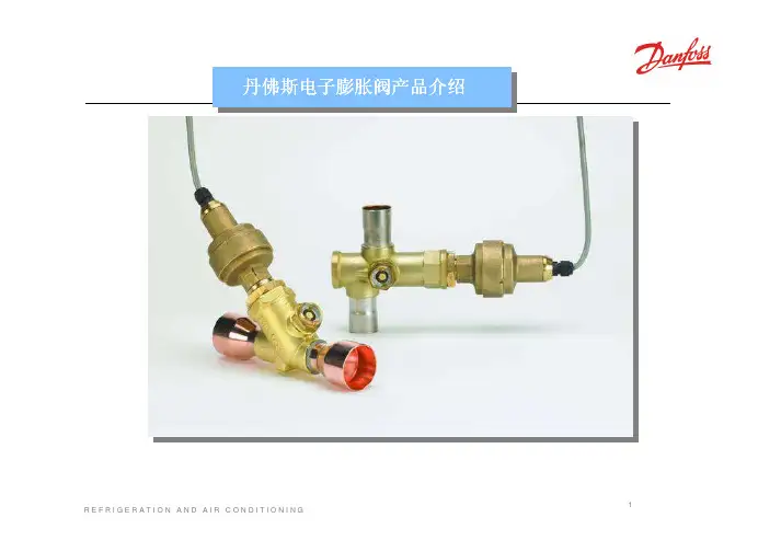
电子膨胀阀控制系统原理,安装调试和故障诊断1, 电子膨胀阀系统原理1.1 系统组成•电子膨胀阀阀体ETS•控制器EKC312•压力传感器AKS33•温度传感器AKS111.2 各个部件的作用•电子膨胀阀,负责根据接受到的脉冲信号控制膨胀阀开度,保证适量的供液量和合适过热度。
•压力传感器:负责检测蒸发压力,并将蒸发压力值转变成4-20mA的电流信号。
•温度传感器:可以根据温度的不同电阻值也不同。
(温度和电阻值对照表参见附件 1)。
•控制器:控制器是该系统的核心器件,作用类似于人体大脑。
控制器可以接受压力传感器送来的4-20mA电流信号,和温度传感器的电阻值信号。
根据这些信号,通过内部的计算发出脉冲信号来控制电子膨胀阀的开度,保证系统供液量和过热度。
正常运转时,控制器显示系统的实际过热度。
1.3 系统工作原理•控制器采样压力传感器送来的4-20mA电流信号,和温度传感器的电阻值信号,计算出当前实际过热度;•参考设定参数,计算出应当达到的要求过热度;•根据实际过热度和要求过热度,结合控制器的参数设定,以一定的反映方式,来调节电子膨胀阀开度,使其尽量靠近要求过热度。
•反复检测两个过热度之间的差异,逐步时事调整膨胀阀开度。
说明,在系统稳定的情况下尽量减小要求过热度,以提高系统效率。
2,电子膨胀阀系统调试2.1系统安装•电子膨胀阀:安装之前必须参考丹佛斯电子膨胀阀的安装指南,每一个电子膨胀阀包装那都有一份安装指南。
注意4个电线的颜色和对应连接。
••控制器:按右图连接对应电线,尤其注意电源符合要求(24V交流)。
•压力传感器:按下图接线。
压力传感器接线必须牢固,压力接口最好在水平铜管的上方,以免杂质堵塞。
如果使用过渡铜管连接压力接口,过渡铜管的长度应当尽量短。
保证压力传感器固定牢固,以免运输震动损坏传感器。
• 温度传感器: 温度传感器必须牢固的紧贴管壁,并用保温层可靠包裹,同时使用卡篐固定。
温度传感器应当仅仅感受吸气温度。
DKRCC.PD.AB0.A3.02 / 520H5227MAKING MODERN LIVING POSSIBLEThe TE series expansion valve regulate the injection of refrigerant into evaporators. It controls the refrigerant flow based on the superheat. The exchangeable power element is produced with the well known Danfoss laser welding technology for extended lifetime capability. The TE series is available with a wide range of orifices which will cover a wide rangeof applications.Technical brochureThermostatic expansion valves type TE5 to TE55Features Large operating range: N-range -40°C to +10°C / B-range -60°C to -25°CInterchangeable orifice assembly.Stainless steel power element, capillary tube and bulb.Wide capacity range. MOP function is available.Superior charge performance. Patented bulb strap design.MWP (maximum working pressure) 28 bar. Wide capacity range to minimize capacity gap and overlap.TE55 has balanced orifice design.2 DKRCC.PD.AB0.A3.02 / 520H5227Danfoss A/S (AC-SMC / sw), 03 - 2011IdentificationElement labelOrifice assembly markingfor TE5 to TE55The thermostatic element is fitted with a label (on top of the diaphragm). The code refers to the refrigerant for which the valve is designed:X = R22N = R134aS = R404A/R507Z = R407CThe label holds information like valve type, evaporating temperature range, MOP point, refrigerant, and max. test pressure, PS.Orifice assembly for TE5, TE12, 20 and 55The orifice assembly is marked on top of the spring cup, e.g. as shown in the figure.For a given size of valve, the same orificeassembly can be used for valves with ranges N and B.TE12 = For valve type 05 = Orifice no.067B2708 = Orifice code no. for sales order 1009 = Production date (Week, Year)Capillary tube tag for TE5 to TE55The label gives the orifice size (04). A new label always accompanies a new orifice assembly.TE5 to TE55Max. temperatureBulb, when valve is assembled: 100°CComplete valve when not assembled: 70°CSS = static superheat OS = opening superheatSH = SS + OS = total superheat Q nom = rated capacityQ max = maximum capacityStatic superheat SS can be adjusted with setting spindle.The standard factory superheat setting SS is 4 K.The opening superheat OS is 4 K from when opening begins to where the valve reaches its rated capacity Q nom .SuperheatExampleStatic superheat SS = 4 K Opening superheat OS = 4 K Total superheat SH = 4 + 4 = 8 KUsing orifice with range B element, please check superheat under running conditions and re-adjust superheat setting, if necessary.Min. temperature: –60°C Max. test pressure: 32 barMaximum working pressure:28 barTechnical dataDanfoss A/S (AC-SMC / sw), 03 - 2011 DKRCC.PD.AB0.A3.02 / 520H52273Design/FunctionGeneralAll TE valves have an interchangeable orifice assembly.TE5 to TE55 valves are built up of three main components:1 - Thermostatic element2 - Orifice assembly3 - Valve body with connectionsThe orifice is refrigerant and range independend.All valves are equipped with external pressure equalization.To ensure long operating life, the valve cone and seat are made of a special alloy with particularly good wear properties.1. Thermostatic element (diaphragm)2. Interchangeable orifice assembly3. Valve body4. Superheat setting spindle (see instructions)5. Ext. pressure equalizing connection with 1⁄4 in./6 mm flare nut4 DKRCC.PD.AB0.A3.02 / 520H5227Danfoss A/S (AC-SMC / sw), 03 - 2011OrderingBulb strap for TE5 to TE55 delivered with the elementDanfoss A/S (AC-SMC / sw), 03 - 2011 DKRCC.PD.AB0.A3.02 / 520H522752) ODF × ODM 3) ODM × ODMODF = Internal diameter ODM = External diameterOrdering(continued)Evaporating temperature t e = +4.4°C Condensing temperaturet c = +38°C Refrigerant temperature ahead of valvet l =+37°C6 DKRCC.PD.AB0.A3.02 / 520H5227Danfoss A/S (AC-SMC / sw), 03 - 2011Subcooling correction factor 'fsub'Capacity in kW, range N, -40°C to +10°C, opening superheat sh= 4 K Q (capacity) = 45kWTcon (condensing temperature) = 25°C Tevap (evaporator temperature) = -30°C Tsub (subcooling temperature) =10K Dpd (distributer pressure drop) = 2 barQ (capacity) = 45kWfsub (subcooling correction factor) = 1.09fp (distribution correction factor) = 0.85Q = Selected capacity fsub x fp45= 48.6 kW1.09 x 0.85The selection will be:TE55 orifice 10 (52.70 kW > 48.6 kW)How to select a valve:Example:Danfoss A/S (AC-SMC / sw), 03 - 2011 DKRCC.PD.AB0.A3.02 / 520H522778 DKRCC.PD.AB0.A3.02 / 520H5227Danfoss A/S (AC-SMC / sw), 03 - 2011Subcooling correction factor ‘fsub’Distributer correction factor ‘fp’Capacity in kW, range N, -40°C to +10°C, opening superheat sh= 4 KQ (capacity) = 45kWTcon (condensing temperature) = 25°C Tevap (evaporator temperature) = -30°C Tsub (subcooling temperature) =10K Dpd (distributer pressure drop) = 2 barQ (capacity) = 45kWfsub (subcooling correction factor) = 1.10fp (distribution correction factor) = 0.92Q = Selected capacity fsub x fp45= 44.5 kW1.10 x 0.92The selection will be:TE20 orifice 8 (48.4 kW > 44.5 kW)How to select a valve:Example:Danfoss A/S (AC-SMC / sw), 03 - 2011 DKRCC.PD.AB0.A3.02 / 520H5227910DKRCC.PD.AB0.A3.02 / 520H5227 Danfoss A/S (AC-SMC / sw), 03 - 2011Subcooling correction factor ‘fsub’Distributer correction factor ‘fp’Capacity in kW, range N, -40°C to +10°C, opening superheat sh= 4 KQ (capacity) = 45kWTcon (condensing temperature) = 25°C Tevap (evaporator temperature) = -30°C Tsub (subcooling temperature) =10K Dpd (distributer pressure drop) = 2 barQ (capacity) = 45kWfsub (subcooling correction factor) = 1.08fp (distribution correction factor) = 0.92Q = Selected capacity fsub x fp45= 45.3 kW1.08 x 0.92The selection will be:TE12 orifice 7 (46.5 kW > 45.3 kW)How to select a valve:Example:Capacity in kW, range N, -40°C to +10°C, opening superheat sh= 4 KSubcooling correction factor 'fsub'Q (capacity) = 45kWTcon (condensing temperature) = 25°C Tevap (evaporator temperature) = -30°C Tsub (subcooling temperature) =10K Dpd (distributer pressure drop) = 2 barQ (capacity) = 45kWfsub (subcooling correction factor) = 1.07fp (distribution correction factor) = 0.90Q = Selected capacity fsub x fp45= 46.7 kW1.07 x 0.90The selection will be:TE12 orifice 7 (53.1 kW > 46.7 kW)How to select a valve Example:Dimensions and weights TE5Dimensions and weights Array(continued)。