丹佛斯电子膨胀阀AKV Catalogue
- 格式:pdf
- 大小:1.70 MB
- 文档页数:13
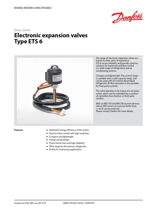
MAKING MODERN LIVING POSSIBLEDanfoss A/S (AC-MCI sw) 2013-10 DKRCC.PD.VD1.D3.02 / 520H7937Data sheetElectronic expansion valves Type ETS 6The range of electronic expansion valves are based on many years of experience.ETS 6 secure reliability and provide a precise solutions for ex p ansion and flow control in a wide range of refrigeration and air conditioning systems.Compact and lightweight. The current range is available with a wide capacity range, and can be used with all common fluorinated refrigerants. Bi-flow operation is also possible for heat pump systems.The valve operation is by means of a uni-polar motor, which can be controlled by a number of controllers from Danfoss or third party vendors.With an EKD 316 and EIM 336 (current drivers) and an AKS sensor, an accuracy better than +/-0.5 K can be obtained.Please contact Danfoss for more details.FeaturesOptimized energy efficiency of the system. Precision flow control with high resolution. Compact and lightweight. Energy saving design.Proven know-how and high reliability. Wide range for all common refrigerants. Bi-flow for heat pump applications.2DKRCC.PD.VD1.D3.02 / 520H7937Danfoss A/S (AC-MCI sw) 2013-10Data sheetElectronic Expansion Valves, type ETS 6Design/functionThe ETS 6 electronic expansion valves open and close to regulate refrigerant flow by means of a screw, whose rotating motion is transformed into linear motion. This occurs by the rotation of a magnet-needle valve assembly whichmoves when electrical signals are applied to the surrounding coil.Within the coil structure, there are different winding configurations, and the polarities arechanged by the electrical signals applied. By application of the appropriate combination of signals, in the form of pulses, the coil forces the rotor of the valve to move in a stepwise fashion.Application of multiple pulses will make the valve mechanism to move through a series of steps in the chosen direction, in order to set the valve with the required opening degree.CoilPermanent magnet motorNeedle valveValve bodyCross section diagram of ETS 6 series* Refers to refrigerant flow in cooling modeOutlet (A*)Inlet (B*)Technical dataFig. 1ApprovalsComplies with: EC PED 97/23/EC a3P3UL, RoHS and CQCRoHSData sheet Electronic Expansion Valves, type ETS 6Danfoss A/S (AC-MCI sw) 2013-10 DKRCC.PD.VD1.D3.02 / 520H79373Electrical wiringStepper motor switch sequenceThe illustration shows the JST XHP-6 connetor. The coil with JST XHP-5 is identical except that it does not have an unused pinCT=38°C, ET=5°C, SC=0°C, SH=0°C*Please contact Danfoss if higher maximum reverse pressure valve is required.1) Max. Reverse Pressure = Pressure as which the valve can still close tightly in reverse direction (from A to B see fig. 1).Valve ordering4 DKRCC.PD.VD1.D3.02 / 520H7937 Danfoss A/S (AC-MCI sw) 2013-10Data sheetElectronic Expansion Valves, type ETS 6For optimum performance, it is important to correct the evaporator capacity. In order toselect the correct size of ETS 6 you will need the following information:Refrigerant: HCFC or HFCEvaporator capacity Q e in kW or TR Evaporating temperature t e in °C or °F Condenser temperature t c in °C or °F Subcooling Δt sub in K or °F ExampleWhen selecting the valve it may be necessary to apply a correction factor to the actual evaporator capacity. This correction factor is required when system conditions are different than tableconditions. Selection also depends on having an acceptable pressure drop across the valve. In the selection table, the pressure drop in the liquid line is assumed to be zero. The following example illustrates correct selection of the valve.Refrigerant: R407CEvaporator capacity: Q e = 10 kW (2.84TR)Condensing temperature: t c = 40°C (104 °F) Evaporating temperature: t e = +10°C (50°F) Subcooling Δt sub = 10 KApplication exampleValve SelectionHeat pump components in typical system.1. Compressor.2. Controller.3. Four-way valve.4. Temperature sensor.5. Pressure transmitter.6. Cartridge pressure control.7. Evaporator.8. Condenser.9. Temperature sensor.10. Electronic expansion valve.11. Sight glass.12. Liquid line filter drier.Data sheetElectronic Expansion Valves, type ETS 6Danfoss A/S (AC-MCI sw) 2013-10 DKRCC.PD.VD1.D3.02 / 520H7937 5Step 1Determine the correction factor for subcooling Δt sub . From the correction factor table (see below) a subcooling of 10 K, R407C corresponds to a factor of 1.14.Correction factors for subcooling Δt sub .Step 2Corrected evaporator capacity isQ e (Corrected) = 10 kW/1.14 = 8.8 kW (2.5 TR)Step 3Select the appropriate capacity table, R407C, and choose the column for condensing temperature of t c = 40°C (104°F) and evaporating temperature of t e = 10°C (50°F) which will provide anequivalent or greater capacity of 8.8 kW (2.5 TR).ETS 6-18 provides 10.35 kW (2.94 TR), which is the proper selection for this example.Step 4Choose ETS 6-18:Single pack code no. 034G5026 I-pack code no. 034G5024Valve Selection (continued)Rated Capacity (kW)Correction factors for subcooling Δt subThe evaporator capacities used must be corrected if subcooling deviates from 0 K.The corrected capacity can be obtained bydividing the required evaporator capacity by the correction factor below. Selections can then bemade from the tables above.6 DKRCC.PD.VD1.D3.02 / 520H7937 Danfoss A/S (AC-MCI sw) 2013-10Data sheetElectronic Expansion Valves, type ETS 6Rated Capacity (kW)Rated Capacity (kW)Data sheetElectronic Expansion Valves, type ETS 6Danfoss A/S (AC-MCI sw) 2013-10 DKRCC.PD.VD1.D3.02 / 520H79377Rated Capacity (kW)Rated Capacity (kW)Data sheetElectronic Expansion Valves, type ETS 6Rated Capacity (kW)8 DKRCC.PD.VD1.D3.02 / 520H7937 Danfoss A/S (AC-MCI sw) 2013-10Data sheetElectronic Expansion Valves, type ETS 6Danfoss A/S (AC-MCI sw) 2013-10 DKRCC.PD.VD1.D3.02 / 520H79379Rated Capacity (TR)Rated Capacity (TR)10 DKRCC.PD.VD1.D3.02 / 520H7937 Danfoss A/S (AC-MCI sw) 2013-10Data sheetElectronic Expansion Valves, type ETS 6Rated Capacity (TR)Rated Capacity (TR)Data sheetElectronic Expansion Valves, type ETS 6Danfoss A/S (AC-MCI sw) 2013-10 DKRCC.PD.VD1.D3.02 / 520H793711Rated Capacity (TR)Rated Capacity (TR)Data sheet Electronic Expansion Valves, type ETS 6 Capacities, continuedConditionsR410 AT e: 5°CT c: 38°C Subcooling: 0°C Superheat: 0°C(B to A ref. drawing page 1)12 DKRCC.PD.VD1.D3.02 / 520H7937 Danfoss A/S (AC-MCI sw) 2013-10Data sheetElectronic Expansion Valves, type ETS 6Danfoss A/S (AC-MCI sw) 2013-10 DKRCC.PD.VD1.D3.02 / 520H7937 13DimensionsETS 6-10ETS 6-14ETS 6-25ETS 6-32ETS 6-40All dimensions in mmETS 6-18All dimensions in mmRelated Danfoss ProductsWeight: 0.16 kg (complete)。


电子膨胀阀控制系统原理安装调试丹弗斯集团企业公司编码:(LL3698-KKI1269-TM2483-LUI12689-ITT289-电子膨胀阀控制系统原理,安装调试1,电子膨胀阀系统原理1.1系统组成电子膨胀阀阀体ETS控制器EKC312压力传感器AKS33温度传感器AKS111.2各个部件的作用电子膨胀阀,负责根据接受到的脉冲信号控制膨胀阀开度,保证适量的供液量和合适过热度。
压力传感器:负责检测蒸发压力,并将蒸发压力值转变成4-20mA的电流信号。
温度传感器:可以根据温度的不同电阻值也不同。
(温度和电阻值对照表参见附件1)。
控制器:控制器是该系统的核心器件,作用类似于人体大脑。
控制器可以接受压力传感器送来的4-20mA电流信号,和温度传感器的电阻值信号。
根据这些信号,通过内部的计算发出脉冲信号来控制电子膨胀阀的开度,保证系统供液量和过热度。
正常运转时,控制器显示系统的实际过热度。
1.3系统工作原理控制器采样压力传感器送来的4-20mA电流信号,和温度传感器的电阻值信号,计算出当前实际过热度;参考设定参数,计算出应当达到的要求过热度;根据实际过热度和要求过热度,结合控制器的参数设定,以一定的反映方式,来调节电子膨胀阀开度,使其尽量靠近要求过热度。
反复检测两个过热度之间的差异,逐步时事调整膨胀阀开度。
说明,在系统稳定的情况下尽量减小要求过热度,以提高系统效率。
2,电子膨胀阀系统调试2.1系统安装电子膨胀阀:安装之前必须参考丹佛斯电子膨胀阀的安装指南,每一个电子膨胀阀包装那都有一份安装指南。
注意4个电线的颜色和对应连接。
控制器:按右图连接对应电线,尤其注意电源符合要求(24V交流)。
压力传感器:按下图接线。
压力传感器接线必须牢固,压力接口最好在水平铜管的上方,以免杂质堵塞。
如果使用过渡铜管连接压力接口,过渡铜管的长度应当尽量短。
保证压力传感器固定牢固,以免运输震动损坏传感器。
温度传感器:温度传感器必须牢固的紧贴管壁,并用保温层可靠包裹,同时使用卡篐固定。

丹佛斯AKS41 ICAD EKC347电动阀使用说明书本系统采用Danfoss的一套组合(AKS41液位传感器+(ICM+ICAD封闭式电动阀)+EKC347控制器)进行供液控制。
EKC347控制器可以根据AKS41液位传感器提供的4~20mA 液位信号来精确控制ICM封闭式电动阀的开度。
以下分别给出AKS41液位传感器、ICAD电动阀马达(电动阀)、EKC347控制器的中文操作指南,如果与英文操作指南有冲突,以英文为准。
一、AKS41液位传感器、ICAD电动阀马达、EKC347控制器的初始设定AKS41液位传感器、ICAD电动阀马达、EKC347控制器必须进行初始设定。
1.1、液位控制器EKC347的设定设定按键●上电几秒,待显示0.00后,才允许开始设定;●同时按住两按钮,进入液位设定状态,显示值会不断闪动,按上下键调定设定值,设定完后再同时按住两键进行确认;●接着上步操作,按住上面的按键不放几秒钟后,可找到其它设置项r06、r12等进行设置;●待所有参数均设定完毕后,放开所有按键,一段时间后,显示自动恢复到原始画面。
注意:显示r12等设定项后,同时按住两键进入参数设定状态,通过按上下两键调定具体设定值,参数值设定完毕后,务必再次同时按住两键进行确认。
LED显示:当前实际液位值,按一下“下按键”,则LED显示为电动阀开度。
功能参数最小值最大值设定值液位控制液位设定值,若需设定液位同时按住两键0% 100% 50% 外部参考值设定R06 -100 100 /液位控制开/停R12 OFF ON/on ON/on 报警液位上限A01 0% 100% 55液位下限A02 0% 100% 451.2、电动阀ICAD马达初始设定●按住中间的○按键几秒钟后,按▲▼键找到i10项,按下○键进入密码输入状态,再通过▲▼键找到密码值(密码为11),然后再按一下○键进行确认;●输入密码后便可以对参数进行设定了,按▲▼键找到需要设定的项,然后按○键,进入参数设定状态,通过按▲▼键设定参数值,参数设定完后,再按一下○键进行确认;设定完后电动阀会进行自动调节,发出嗡嗡的震动,且显示100%,说明设定正确。

MAKING MODERN LIVING POSSIBLETechnical brochureThermostatic expansion valvetype TGEHydrocarbons/hydrocarbons2DKRCC.PD.AXV.C1.02 / 520H4822 Produced by Danfoss A/S © (RA-MC / mr) Sep 2010Technical brochureThermostatic expansion valves, type TGE10, TGE20, TGE40IntroductionTGE is a new dedicated designed series of thermostatic expansion valve with lots of tech-nical innovations for all normal refrigerants including R410A, TGE valve for HC refriger-ants is a further development of the existing series for HFC and HCFC refrigerants. The new development of TGE can be adopted to special requirements. Meanwhile, the materials used for the new refrigerants were chosen to ensure compatibility between them and HC + oil. Standard information can be found in gen-eral leaflet.FeaturesHermetic TXV for R290Version with MOP(Max. Operating Pressure)Straightway flow Balance port (BP)Low hysteresisOpening superheat (OSH) max.4o K Max. working pressure 46 bar / 667 psiLifetime for heat pump applicationCylindrical bulb design, with new bulb strap Biflow with expansion in both directions Adjustable superheat settingLaser welded, improved stainless steel power element / capillary tubeMechanical connections (flare. MIO, ORFS) availableTechnical dataMaximum operating temperature - Thermostatic element N change: 100o C / 210o F K change: 150o C / 302o F Valve body: 110o C / 230o F Max. working pressure46 bar / 667 psigMax. test pressure 51 bar / 740 psigTGE valves are designed with balance port for biflow applicationsFlammable / Toxic refrigerants R290Terms of deliveryIt should be noted that special terms of delivery apply to Danfoss controls for HC and corresponding flammable refrigerants. Please refer to Danfoss literature RZ0ZM (agreement on the application of HCrefrigerants). All inquiries for TGE for HC will be dealt with as “inquiries for special versions”.Delivery agreements on components can only be entered into within the EU or EFTA, and the export and re-export of plants or sections of plants containing Danfosscomponents are also limited to the EU and EFTA.3Produced by Danfoss A/S © (RA-MC / mr) Sep 2010DKRCC.PD.AXV.C1.02 / 520H4822Technical brochureThermostatic expansion valves, type TGE10, TGE20, TGE40Product technologyThe use of Danfoss TGE for R290 and R1270 in refrigeration plants is subject to explosion protection regulations for danger zone 2 (only rare or short term threat).The Danfoss controls are, therefore, developed for this above-mentionedrequirement.Only Danfoss valves and controls released for use with flammable hydrocarbons must be used with these substances. The actual me-dium must be stated in the product data sheet and / or on the product.Only original Danfoss spare parts approved for use with flammable hydrocarbons must be used.TGE complies with the requirements for explo-sive atmospheres (94/9/EC) ac. ATEX zone 2. TGE is marked with a label that indicates fire hazard (B.3.2 / ISO 3864).TGE complies with the requirements in the Pressure Equipment Directive (PED) (97/23/ EC) fluid group I (flammable/toxic media). TGE is marked with a label that indicates fire hazard (B.3.2 / ISO 3864).Technical safety require-mentsThe refrigeration system must be located with-in the EU or EFTA and comply with the exist-ing EU legislation, such as the Pressure Equipment Directive (PED) (97/23/EC), the directive concerning potential explosive atmospheres (ATEX) (94/9/EC), EN 378, and other relevant EU legislation.The refrigeration system must always comply with any local directive, legislation, and any other regulation applying in the area of installation.Installation and mainte-nanceOnly authorized persons, who are certified in installing and maintaining refrigeration plants containing flammable hydrocarbons, may do the installation and maintenance.All requirements from local authorities, regard-ing use of hydrocarbons in refrigeration sys-tems, must be fulfilled.The refrigeration system must be designed in such a way that no abnormal impact (e.g. abnormal vibration, liquid hammer, or pressure pulsations) can create risk for damage of the refrigeration system during operation.Only original Danfoss spare parts approved for use with flammable hydrocarbons may be used.The Danfoss products are classified accord-ing to the ATEX directive. Danfoss takes no responsibility for the classification of the refrig-eration system.4DKRCC.PD.AXV.C1.02 / 520H4822 Produced by Danfoss A/S © (RA-MC / mr) Sep 2010Technical brochureThermostatic expansion valves, type TGE10, TGE20, TGE40IdentificationImportant valve information is provided on the diaphragm element (fig.1).Main valve date example:TGE20 = Valve type12TR = Rated capacity Q nom in the tons of refrigeration 44kW = Rated capacity Q nom in kW R290 = Refrigerant-40/+10o C = Evaporating temperature range (o C)-40/+50o F = Evaporating temperature range (o F)067N9104 = Code number PS 46barMWP 670 Psig = Max. Working Pressure in bar and psig.090312 = product time (March 12th,2009)OrderingThe valve and bulb straps are supplied in industrial packs or multi packs:Industrial pack, TGE10/12pcs Multi pack, TGE10/12pcs Industrial pack, TGE20/8pcs Multi pack, TGE20/8pcs Industrial pack, TGE40/8pcs Multi pack, TGE40/6pcs5Produced by Danfoss A/S © (RA-MC / mr) Sep 2010DKRCC.PD.AXV.C1.02 / 520H4822Technical brochureThermostatic expansion valves, type TGE10, TGE20, TGE40OrderingStandard rangeTGE description TGE Capacity TGEconnection (in.)TGE Code No.Multi pack TGE Code No.Industrial pack Range N = -40 → + 10o CR290TGE1019⁵⁄₈ x 7⁄₈067N9100067N9140TGE1025⁵⁄₈ x 7⁄₈067N9101067N9141TGE1025⁵⁄₈ x 7⁄₈067N9101067N9141TGE10367⁄₈ x 7⁄₈067N9102067N9142TGE1036⁵⁄₈ x 7⁄₈067N9103TGE10367⁄₈ x 7⁄₈067N9142TGE2043⁵⁄₈ x 7⁄₈067N9104067N9144TGE20547⁄₈ x 7⁄₈067N9105067N9145TGE20617⁄₈ x 7⁄₈067N9106067N9146TGE20617⁄₈ x 7⁄₈067N9106067N9146TGE40947⁄₈ x 7⁄₈067N9147TGE401067⁄₈ x 7⁄₈067N9108067N9148TGE401357⁄₈ x 7⁄₈067N9149Conditions R290: Condensations temperature 38 o C Evap. temperature 4 o C Liquid temperature 37 o C6DKRCC.PD.AXV.C1.02 / 520H4822 Produced by Danfoss A/S © (RA-MC / mr) Sep 2010Technical brochureThermostatic expansion valves, type TGE10, TGE20, TGE40CapacityR290Capacity in kW for range N and superheat OS = 4 KType and rated capacity Q nom TRPressure drop across the valve ∆p barPressure drop across the valve ∆p bar 246810121416246810121416Evaporating temperature +15°CEvaporating temperature +10°CTGE 10-3 TGE 10-4 TGE 10-6TGE 10-8TGE 10-117.7310.5815.6620.7727.5510.0313.7020.2026.7535.9511.3215.4122.6429.9240.7411.9816.2623.7931.3943.3112.2516.5924.1831.8444.5012.3116.6224.1331.7144.8912.2016.4323.7731.1744.6811.9716.0723.1730.3344.027.469.4114.0618.9025.719.6612.1518.0724.2433.3910.8613.6220.1827.0137.6911.4014.2721.0628.1239.7211.6514.5421.3728.4640.7111.6814.5521.2928.3040.9711.5714.3720.9527.7940.6911.3414.0520.4127.0040.01TGE 20-12.5TGE 20-16TGE 20-2035.2945.4251.8144.8257.4166.1949.5063.2373.3751.2965.2476.1751.4365.1576.3450.6663.9375.0149.2961.9772.6147.4859.4969.45 33.98 43.7250.2842.9755.0263.8047.2760.2370.2648.5961.6572.1348.6161.4171.8847.8060.1470.3146.4458.2068.2644.6855.8065.63TGE 40-26TGE 40-30TGE 40-4080.5391.40108.70100.70114.20139.20109.50124.10154.80111.90126.70161.20110.70125.30162.20107.70121.80160.10103.50117.00155.7098.60111.40149.7077.4288.04105.1096.27109.40133.70104.20118.30147.80105.60119.70152.30104.10118.00152.50101.10114.40149.7096.95109.70144.8092.20104.20138.50Evaporating temperature +5°C Evaporating temperature 0°CTGE 10-3TGE 10-4TGE 10-6TGE 10-8TGE 10-117.179.0213.5218.2725.119.2411.6017.3023.3232.4810.3012.8919.1525.7436.3110.7913.4719.9226.7238.1611.0013.7020.1726.9839.0111.0213.6920.0726.7739.1810.9013.5019.7226.2338.8410.6713.1919.1825.4538.11 6.848.5912.9117.5424.358.7810.9916.4522.2731.339.6912.1118.0224.3334.6810.1312.6218.7025.1836.3310.3112.8118.8925.3637.0410.3112.7718.7625.1137.1010.1812.5818.4024.5536.709.9612.2717.8723.7835.93TGE 20-12.5TGE 20-16TGE 20-2032.4541.7448.4340.8452.2760.9944.5056.6766.3045.6257.8267.7245.5357.4767.5344.6956.1766.2143.3554.2764.1441.6551.9661.5630.7439.5446.2438.5049.2657.7841.5452.8762.2442.4653.7863.5242.2853.3263.1641.4352.0261.7840.1150.1759.7138.4947.9657.20TGE 40-26TGE 40-30TGE 40-4074.0184.33100.9091.52104.20127.6098.07111.50139.2098.98112.40142.6097.36110.40141.9094.26106.80138.5090.25102.20133.3085.6896.88126.7070.2080.1396.1186.2998.37120.5091.48104.10129.8091.99104.60132.0090.23102.40130.5087.1598.82126.5083.2794.31120.8078.9189.27113.90Evaporating temperature -5°C Evaporating temperature –10°CTGE 10-3TGE 10-4TGE 10-6TGE 10-8TGE 10-11 6.498.1312.2616.7323.468.2710.3515.5221.1029.989.0611.3016.8522.8532.879.4511.7517.4423.5634.329.6011.9017.5823.6734.889.5811.8517.4223.3834.859.4511.6517.0522.8234.389.2311.3516.5422.0633.58 6.117.6511.5615.8422.427.709.6114.4519.7328.288.4010.4615.6321.2730.878.7410.8516.1321.8732.118.8610.9616.2221.9132.538.8310.9016.0421.5932.398.7010.7015.6821.0331.858.4810.4115.1720.2831.01TGE 20-12.5TGE 20-16TGE 20-2028.9337.2143.8936.0046.0554.5038.5048.9858.1539.2549.6859.1439.0049.1458.6438.1447.8557.2236.8846.0755.1935.3443.9852.7627.0134.7441.3433.2142.4650.6835.3844.9953.8335.9745.5154.5635.6844.9253.9534.8343.6552.5233.6341.9650.5532.1839.9948.23TGE 40-26TGE 40-30TGE 40-4066.1375.6190.8380.6992.11112.7084.7196.54119.8084.9096.61120.9083.0494.36118.6080.0290.79114.0076.3086.46107.9072.1881.68100.8061.7970.7685.0474.4085.04103.8077.7688.72109.2077.6788.46109.3075.7786.15106.2072.8482.69101.1069.3278.5794.8465.4574.0889.58Evaporating temperature -15°C Evaporating temperature –20°CTGE 10-3TGE 10-4TGE 10-6TGE 10-8TGE 10-11 5.727.1410.8214.8921.277.128.8713.3618.3126.467.749.6214.4019.6628.748.049.9514.8220.1529.778.1310.0414.8720.1330.058.099.9614.6719.7929.817.959.7614.3119.2329.217.749.4813.8218.5128.33 5.3166.64110.0813.9220.04 6.5378.1412.2816.8924.587.0888.79813.218.0626.567.349.08213.5418.4627.397.4119.14313.5518.3927.537.3619.05413.3518.0427.27.2248.85912.9917.4826.537.0218.58612.5216.7925.62TGE 20-12.5TGE 20-16TGE 20-2025.0332.2038.6430.4038.8646.7332.2841.0249.4332.7441.3949.9532.4140.7749.2631.5939.5547.8430.4537.9645.9629.1036.1343.7623.0729.6735.8727.6535.3442.7929.2837.1945.0929.6437.4445.4429.2936.8144.728.5135.6643.3227.4434.1741.5326.1932.4739.48TGE 40-26TGE 40-30TGE 40-4057.2965.7178.9268.0777.8994.5270.8480.8998.5070.5380.3997.5668.6378.0893.9665.8474.7790.1862.5370.8985.6858.9466.7180.7652.7960.6272.6861.8570.8685.364.1273.2887.8763.6672.5987.2961.870.3384.7759.1667.1981.1556.0863.5876.9252.7759.7272.347Produced by Danfoss A/S © (RA-MC / mr) Sep 2010DKRCC.PD.AXV.C1.02 / 520H4822Technical brochureThermostatic expansion valves, type TGE10, TGE20, TGE40Capacity (Continued )R290Capacity in kW for range N and superheat OS = 4 KType and rated capacity Q nom TRPressure drop across the valve ∆p barPressure drop across the valve ∆p bar246810121416246810121416Evaporating temperature -25°CEvaporating temperature –30°CTGE 10-3TGE 10-4TGE 10-6TGE 10-8TGE 10-11 4.906.119.3012.8918.68 5.947.3911.1815.4122.56 6.437.9711.9716.4224.24 6.648.2112.2516.7324.88 6.698.2412.2316.6324.88 6.638.1512.0216.2624.46 6.507.9611.6715.7223.73 6.307.7011.2215.0622.78 4.455.568.4711.7817.18 5.376.6910.1213.9920.56 5.797.1810.8014.8621.97 5.977.3811.0315.0922.42 6.017.4010.9814.9522.29 5.947.3010.7714.5921.78 5.817.1210.4314.0721.00 5.626.8710.0113.4420.03TGE 20-12.5TGE 20-16TGE 20-2021.0227.0532.9224.8831.8038.7426.2733.3740.6826.5533.5240.8826.2032.9040.1425.4731.8238.8224.4930.4637.1523.3428.9135.2518.9124.3429.8122.2728.4634.8623.4729.8036.5023.6829.8836.6023.3429.2935.8622.6728.3034.6221.7727.0533.0720.7325.6431.33TGE 40-26TGE 40-30TGE 40-4048.1155.3266.0855.5963.7476.3457.4265.6778.8956.8664.8778.1355.0862.7075.6752.6359.7872.2749.8156.4668.3446.7852.9364.1443.2449.7859.5549.6657.0068.4051.1458.5270.4250.5357.6769.5448.8555.6167.1846.6052.9264.0144.0349.8960.4141.2946.6956.57Evaporating temperature -35°C Evaporating temperature –40°CTGE 10-3TGE 10-4TGE 10-6TGE 10-8TGE 10-11 4.025.027.6610.6815.65 4.826.019.1112.6218.59 5.196.449.6913.3519.73 5.336.609.8713.5220.00 5.356.619.8113.3619.76 5.296.509.5913.0019.17 5.166.329.2712.5018.34 4.986.098.8711.9117.34 3.604.516.899.6314.17 4.305.388.1611.3216.68 4.615.758.6511.9417.58 4.745.888.7912.0617.69 4.745.878.7111.8817.37 4.675.768.5011.5316.83 4.555.598.1911.0516.12 4.385.387.8210.5015.29TGE 20-12.5TGE 20-16TGE 20-2016.6821.7326.7619.8125.3231.1520.8426.4532.5321.0026.4932.5520.6825.9431.8420.0725.0330.6919.2623.9029.2818.3222.6327.6914.9819.2923.8717.5322.4027.6818.4223.3728.8418.5523.3928.8218.2622.8828.1517.7022.0527.0916.9721.0425.8016.1419.9024.37TGE 40-26TGE 40-30TGE 40-4038.5444.4253.2644.0550.6060.8445.2451.8062.4344.6150.9361.4843.0649.0259.2541.0146.5756.3438.6943.8353.0536.2340.9549.5834.1139.3647.3138.8444.6453.7839.8045.5955.0239.1944.7454.0637.7742.9951.9835.9240.7849.3233.8538.3246.3531.6535.7543.238DKRCC.PD.AXV.C1.02 / 520H4822 Produced by Danfoss A/S © (RA-MC / mr) Sep 2010Technical brochureThermostatic expansion valves, type TGE10, TGE20, TGE40Dimensions and weightsTypeConnection inlet × outlet ODF solder Capillary tube length mH 1mmH 2mmH 3mmH 4mmL 1mm L 2mm L 3mmL 4mmØD 1mmØD 2mmWeight kgin.mm TGE 103/8 × 5/810 × 16 1.528.57.559341.545.537.5704514.50.371/2 × 5/812 × 161/2 × 7/812 × 2259.55/8 × 5/845.545.55/8 × 7/816 × 2259.55/8 × 11/8TGE 205/8 × 7/816 × 22 1.53298117486240785319.20.577/8 × 7/8625/8 × 11/816 × 2848667/8 × 11/822 × 28627/8 × 13/8TGE 407/8 × 13/822 × 35339151114474.543.5786019.20.9311/8 × 11/869.569.511/8 × 13/828 × 3574.5。
电子膨胀阀控制策略根据运转状态,使用步进电机调节电子膨胀阀的开度。
电子膨胀阀包括:小流量CKV,大流量CKV和AKV。
(1) 步进电机的规格电子膨胀阀 CKV AKV SKV 全闭 0脉冲 0脉冲 0脉冲全开 60脉冲 552脉冲 511脉冲励磁方式 1-2相励磁 1-2相励磁 1-2相励磁励磁速度 30PPS 80PPS 30PPS[CKV]·步进式电机停止时也进行通电。
但是,停止时,按周期11毫秒、占空比45%的脉冲通电。
·运转开始时,以停止时的相进行500毫秒的全通电,再发送脉冲。
·运转结束后,以结束的相进行500毫秒的全通电,然后脉冲通电。
[AKV、SKV]·步进电机停止时不进行通电。
·运转开始时,以停止时的相进行500毫秒的全通电,再发送脉冲。
·运转结束后,以结束的相进行500毫秒的全通电,然后停止通电。
1-2相励磁样式(通用)STEP A相 B相 .c相 .d相8N+0 ○ × × ×8N+1 ○ ○ × ×8N+2 × ○ × ×8N+3 × ○ ○ ×8N+4 × × ○ ×8N+5 × × ○ ○8N+6 × × × ○8N+7 ○ × × ○·N表示整数。
·向目标脉冲,一个个脉冲输出。
·到达目标脉冲后,切断输出。
(AKV、SKV)·到达目标脉冲后,脉冲通电。
(CKV)·STEP 增大为开启方向。
·STEP 减小为闭合方向。
(3) 位置检出.微处理器初始化时,以及室内机停止运转时(室温控制中的停止、预约定时、除霜中的停止等除外)进行如下的位置检出。
[CKV]微处理器初始化时,朝闭合方向进行64脉冲输出,在此处重新设置为0脉冲。
Data sheetThermostatic expansion valve Type TUB/TUBE and TUC/TUCEIntroductionThe TU series of thermostatic expansion valves has been developed for soldering into hermetic refrigeration systems.TU valves are made of stainless steel and are therefore very suitable for use in the food industry.TU valves can be used in many forms of refrigeration systems, in particular:-Traditional refrigeration systems -Heat pump systems -Air conditioning units -Refrigeration appliances -Liquid coolers-Ice cube machines-Mobile refrigeration systemsAll variants are available in both single packs and industrial packs as required by the customer.TUB/TUBE have adjustable superheat and are available in angleway versions as standard.TUC/TUCE have fixed superheat, but are otherwise identical to TUB.TUB/TUBE and TUC/TUCE can be delivered in straightway versions.All straightway versions and TUC valves are produced to order and therefore this catalogue contains no description of a standard range or code numbers.TU valves are also available in a number of variants that give countless combination possibilities.Contact Danfoss for further information.Features·Bimetal connections-straightforward and fast soldering (no wet cloth or refrigeration pliers required).·RefrigerantsR 22, R 134a, R 404A, R 507, R 407C,R 410A and future refrigerants·Capacities from 0.6 to 16 kW (0.17 to 4.5 TR)for R 22-large capacity range in small steps ·Stable regulation·Biflow function (orifice 0 to 8)·Compact design- small dimensions and low weight ·Stainless steel, hermetically tight solder version-high connection strength -high corrosion resistance-capillary tube joints of high strength and vibration resistance·Laser-welded, stainless steel thermostatic diaphragm element -optimum function -long diaphragm life-high pressure resistance·Stainless steel double contact bulb -straightforward and fast installation -good heat transfer from bulb to pipe ·Adjustable superheat type (TUB/TUBE)-accurate setting-adjustable in operation·Fixed superheat type (TUC/TUCE)·Filter with high dirt retention capacity ·Available with self-cleaning bleed·Available with MOP (Max. Operating Pressure)Data sheet Thermostatic expansion valve, type TUB/TUBE and TUC/TUCEMax. bulb temperature100°C Max. valve body temperature 120°C,short-lived peak 150°CPermissible working pressure (excl. R 410A)PB =28 bar Max. working pressure, R 410A PB =42.5 bar Max. test pressure (excl. R 410A)p’ =36 bar Max. test pressure, R 410A p’ =47 barBiflow operationWith flow in the opposite direction, the rated capacity is reduced by up to 15%.TUBE with orifice 9, TUB and valves with MOP charges cannot be used for biflow operation.Technical dataMOP-pointsRange N Range NM Range B Refrigerant -40 ® +10°C -40 ® -5°C -60 ® -25°C MOP point for evaporating temperature t e and evaporating pressure p e 1)t e = +15°C/+60°F t e = 0°C/+32°F t e = -20°C/-4°F R 22p e = 100 psig/6.9 bar p e = 60 psig/4.0 bar p e = 20 psig/1.5 bar R 134ap e = 55 psig/3.9 bar p e = 30 psig/1.9 bar R 404A / R 507p e = 120 psig/8.4 bar p e = 75 psig/5.0 bar p e = 30 psig/2.0 bar R 407C p e = 95 psig/6.6 bar p e = 50 psig/3.6 bar p e =15 psig/1.1 bar R 410Ap e = 165 psig/11.5 bar p e = 100 psig/7.0 bar p e =45 psig/3.0 barTo avoid charge migration when MOP valves are used, the bulb temperature must be lower than the thermostatic element temperature.MOP valves1)p e in bar gaugeFor further information,please contact Danfoss.Capillary tube length: 1.5 m Bleed: 15%Connections:Inlet Orifice 0 ® 63/8 in./10 mm Orifice 7 ® 91/4 in./6 mm Straightway only1/2 in./12 mm Outlet3/8 in./10 mm Straightway only5/8 in./16 mmCapacity, orifice variants:In addition to the standard range, valves with orifice 0 are available for R 134a, R 404A and R 507.Variant rangeIn addition to the standard range, TUB/TUBE and TUC/TUCE valves are also available in these variants and variant combinations:Straightway versions Range N -40 ®+10°C MOP +15°C Range NM -40 ®-5°C MOP 0°C Range B -60 ®-25°C Range B–60 ®-25°CMOP -20°CStatic superheat (SS):2 K,3 K,4 K, or 6 K (applies to TUB/TUBE and TUC/TUCE – see fig. 5)Capillary tube length: 0.8 m Connections:Inlet Orifice 0 ® 61/4 in./6 mm Orifice 7 ® 93/8 in./10 mm Outlet1/2 in./12 mmStandard range Versions available in the standard range:Range N : -40 to +10°C without MOP Static superheat (SS):R 22, R 134a, R 404A, R 407C, R 410A = 5 K R 507 = 6.4 KData sheet Thermostatic expansion valve, type TUB/TUBE and TUC/TUCERange N = -40 ® +10 °CR 22, R 134a, R 404A/R 507Ordering AnglewaySupplied with bulb strap Standard valve rangeValves with inch connections have 1/4 in. pressure equalisation.Valves with mm connections have 6 mm pressure equalisation.1)Rated capacity Q nom. is based on:Evaporating temperature t e = +5°CCondensing temperature t c = +32°CRefrigerant liquid temperature t l = +28°COpening superheat OS = 4 K2)TUBE with orifice 9 and TUB (internal pressure equalisation)cannot be used for biflow operation.Refri-TypeRated Orifice Pres-Connection gerantcapacity no.2)sure Inlet ´ OutletQ nom. 1)equali-kW TR sation inch Code no.mm Code no.TUB 0.60.170int.1/4 ´ 1/2068U20566 ´ 12068U2036TUB 0.90.251int.1/4 ´ 1/2068U20576 ´ 12068U2037TUB 1.30.362int.1/4 ´ 1/2068U20586 ´ 12068U2038TUB 1.80.503int.1/4 ´ 1/2068U20596 ´ 12068U2039TUB 2.60.754int.1/4 ´ 1/2068U20606 ´ 12068U2040TUB 3.5 1.005int.1/4 ´ 1/2068U20616 ´ 12068U2041TUB 5.3 1.506int.1/4 ´ 1/2068U20626 ´ 12068U2042TUB 7.0 2.007int.3/8 ´ 1/2068U206310 ´ 12068U2043TUB 11.0 3.008int.3/8 ´ 1/2068U206410 ´ 12068U2044TUB 16.0 4.509int.3/8 ´ 1/2068U206510 ´ 12068U2045R 22TUBE 0.60.170ext.1/4 ´ 1/2068U20666 ´ 12068U2046TUBE 0.90.251ext.1/4 ´ 1/2068U20676 ´ 12068U2047TUBE 1.30.362ext.1/4 ´ 1/2068U20686 ´ 12068U2048TUBE 1.80.503ext.1/4 ´ 1/2068U20696 ´ 12068U2049TUBE 2.60.754ext.1/4 ´ 1/2068U20706 ´ 12068U2050TUBE 3.5 1.005ext.1/4 ´ 1/2068U20716 ´ 12068U2051TUBE 5.3 1.506ext.1/4 ´ 1/2068U20726 ´ 12068U2052TUBE 7.0 2.007ext.3/8 ´ 1/2068U207310 ´ 12068U2053TUBE 11.0 3.008ext.3/8 ´ 1/2068U207410 ´ 12068U2054TUBE 16.0 4.509ext.3/8 ´ 1/2068U207510 ´ 12068U2055TUB 0.70.191int.1/4 ´ 1/2068U20276 ´ 12068U2000TUB 1.00.282int.1/4 ´ 1/2068U20286 ´ 12068U2001TUB 1.40.393int.1/4 ´ 1/2068U20296 ´ 12068U2002TUB 2.10.594int.1/4 ´ 1/2068U20306 ´ 12068U2003TUB 2.70.785int.1/4 ´ 1/2068U20316 ´ 12068U2004TUB 4.1 1.206int.1/4 ´ 1/2068U20326 ´ 12068U2005TUB 5.5 1.607int.3/8 ´ 1/2068U203310 ´ 12068U2006TUB 8.2 2.308int.3/8 ´ 1/2068U203410 ´ 12068U2007TUB 12.0 3.509int.3/8 ´ 1/2068U203510 ´ 12068U2008R 134aTUBE 0.70.191ext.1/4 ´ 1/2068U20186 ´ 12068U2009TUBE 1.00.282ext.1/4 ´ 1/2068U20196 ´ 12068U2010TUBE 1.40.393ext.1/4 ´ 1/2068U20206 ´ 12068U2011TUBE 2.10.594ext.1/4 ´ 1/2068U20216 ´ 12068U2012TUBE 2.70.785ext.1/4 ´ 1/2068U20226 ´ 12068U2013TUBE 4.1 1.206ext.1/4 ´ 1/2068U20236 ´ 12068U2014TUBE 5.5 1.607ext.3/8 ´ 1/2068U202410 ´ 12068U2015TUBE 8.2 2.308ext.3/8 ´ 1/2068U202510 ´ 12068U2016TUBE 12.0 3.509ext.3/8 ´ 1/2068U202610 ´ 12068U2017TUB 0.70.191int.1/4 ´ 1/2068U20946 ´ 12068U2076TUB 1.00.282int.1/4 ´ 1/2068U20956 ´ 12068U2077TUB 1.40.393int.1/4 ´ 1 /2068U20966 ´ 12068U2078TUB 2.10.604int.1/4 ´ 1/2068U20976 ´ 12068U2079TUB 2.80.795int.1/4 ´ 1/2068U20986 ´ 12068U2080TUB 4.2 1.206int.1/4 ´ 1/2068U20996 ´ 12068U2081TUB 5.6 1.607int.3/8 ´ 1/2068U210010 ´ 12068U2082TUB 8.4 2.408int.3/8 ´ 1/2068U210110 ´ 12068U2083TUB 12.0 3.509int. 3/8 ´ 1/2068U210210 ´ 12068U2084R 404A TUBE 0.70.191ext.1/4 ´ 1/2068U21036 ´ 12068U2085R 507TUBE 1.00.282ext.1/4 ´ 1/2068U21046 ´ 12068U2086TUBE 1.40.393ext.1/4 ´ 1/2068U21056 ´ 12068U2087TUBE 2.10.604ext.1/4 ´ 1/2068U21066 ´ 12068U2088TUBE 2.80.795ext.1/4 ´ 1/2068U21076 ´ 12068U2089TUBE 4.2 1.206ext.1/4 ´ 1/2068U21086 ´ 12068U2090TUBE 5.6 1.607ext.3/8 ´ 1/2068U210910 ´ 12068U2091TUBE 8.4 2.408ext.3/8 ´ 1/2068U211010 ´ 12068U2092TUBE12.03.509ext.3/8 ´ 1/2068U211110 ´ 12068U2093Data sheet Thermostatic expansion valve, type TUB/TUBE and TUC/TUCER 407C, R 410ARange N = -40 ® +10 °CRefri-TypeRated Orifice Pres-Connection gerantcapacity no.2)sure Inlet ´ OutletQ nom. 1)equali-kW TR sation inch Code no.mm Code no.TUB 0.630.180int.1/4 ´ 1/2068U1920 6 ´ 12068U1900TUB 0.920.261int.1/4 ´ 1/2068U1921 6 ´ 12068U1901TUB 1.40.382int.1/4 ´ 1/2068U1922 6 ´ 12068U1902TUB 1.90.533int.1/4 ´ 1/2068U1923 6 ´ 12068U1903TUB 2.80.804int.1/4 ´ 1/2068U1924 6 ´ 12068U1904TUB 3.8 1.105int.1/4 ´ 1/2068U1925 6 ´ 12068U1905TUB 5.7 1.606int.1/4 ´ 1/2068U1926 6 ´ 12068U1906TUB 7.5 2.107int.3/8 ´ 1/2068U192710 ´ 12068U1907TUB 11.0 3.208int.3/8 ´ 1/2068U192810 ´ 12068U1908TUB 17.0 4.809int.3/8 ´ 1/2068U192910 ´ 12068U1909R 407CTUBE 0.630.180ext.1/4 ´ 1/2068U1930 6 ´ 12068U1910TUBE 0.920.261ext.1/4 ´ 1/2068U1931 6 ´ 12068U1911TUBE 1.40.382ext.1/4 ´ 1/2068U1932 6 ´ 12068U1912TUBE 1.90.533ext.1/4 ´ 1/2068U1933 6 ´ 12068U1913TUBE 2.80.804ext.1/4 ´ 1/2068U1934 6 ´ 12068U1914TUBE 3.8 1.105ext.1/4 ´ 1/2068U1935 6 ´ 12068U1915TUBE 5.7 1.606ext.1/4 ´ 1/2068U1936 6 ´ 12068U1916TUBE 7.5 2.107ext.3/8 ´ 1/2068U193710 ´ 12068U1917TUBE 11.0 3.208ext.3/8 ´ 1/2068U193810 ´ 12068U1918TUBE 17.0 4.809ext.3/8 ´ 1/2068U193910 ´ 12068U1919TUB 0.820.230int.1/4 ´ 1/2068U1798 6 ´ 12068U1796TUB 1.30.41int.1/4 ´ 1/2068U1958 6 ´ 12068U1940TUB 2.10.62int.1/4 ´ 1/2068U1959 6 ´ 12068U1941TUB 2.90.83int.1/4 ´ 1/2068U1960 6 ´ 12068U1942TUB 4.5 1.34int.1/4 ´ 1/2068U1961 6 ´ 12068U1943TUB 5.9 1.75int.1/4 ´ 1/2068U1962 6 ´ 12068U1944TUB 9.0 2.56int.1/4 ´ 1/2068U1963 6 ´ 12068U1945TUB 12.0 3.47int.3/8 ´ 1/2068U196410 ´ 12068U1946TUB 18.0 5.08int.3/8 ´ 1/2068U196510 ´ 12068U1947TUB 26.07.59int.3/8 ´ 1/2068U196610 ´ 12068U1948 R 410ATUBE 0.820.230ext.1/4 ´ 1/2068U1799 6 ´ 12068U1797TUBE 1.30.41ext.1/4 ´ 1/2068U1967 6 ´ 12068U1949TUBE 2.10.62ext.1/4 ´ 1/2068U1968 6 ´ 12068U1950TUBE 2.90.83ext.1/4 ´ 1/2068U1969 6 ´ 12068U1951TUBE 4.5 1.34ext.1/4 ´ 1/2068U1970 6 ´ 12068U1952TUBE 5.9 1.75ext.1/4 ´ 1/2068U1971 6 ´ 12068U1953TUBE 9.0 2.56ext.1/4 ´ 1/2068U1972 6 ´ 12068U1954TUBE 12.0 3.47ext.3/8 ´ 1/2068U197310 ´ 12068U1955TUBE 18.0 5.08ext.3/8 ´ 1/2068U197410 ´ 12068U1956TUBE26.07.59ext.3/8 ´ 1/2068U197510 ´ 12068U1957Valves with inch connections have 1/4 in. pressure equalisation.Valves with mm connections have 6 mm pressure equalisation.1)Rated capacity Q nom. is based on:Evaporating temperature t e = +5°CCondensing temperature t c = +32°CRefrigerant liquid temperature t l = +28°COpening superheat OS = 4 K2)TUBE with orifice 9 and TUB (internal pressure equalisation)cannot be used for biflow operation.Ordering AnglewaySupplied with bulb strap Standard valve rangeData sheet Thermostatic expansion valve, type TUB/TUBE and TUC/TUCER 22CapacityPressure drop across valve D p bar 246810121416Evaporating temperature 0°C 0.400.500.560.600.630.650.670.670.550.710.800.860.910.930.950.960.73 1.0 1.1 1.2 1.3 1.3 1.4 1.41.0 1.3 1.5 1.7 1.8 1.8 1.9 1.91.5 2.0 2.3 2.5 2.7 2.8 2.8 2.82.0 2.7 3.1 3.4 3.5 3.7 3.8 3.83.1 4.0 4.6 5.0 5.3 5.5 5.7 5.84.1 5.4 6.2 6.77.17.47.67.76.18.09.210.110.611.011.311.59.112.113.815.015.916.416.817.1Evaporating temperature -20°C 0.400.450.480.500.520.530.530.510.570.620.650.670.680.690.610.700.760.790.820.840.850.9 1.0 1.1 1.1 1.2 1.2 1.21.3 1.5 1.6 1.6 1.7 1.7 1.81.7 1.9 2.1 2.2 2.3 2.3 2.32.5 2.9 3.1 3.3 3.4 3.5 3.53.4 3.9 4.2 4.4 4.5 4.6 4.75.1 5.8 6.3 6.6 6.87.07.17.68.69.39.710.110.310.4Evaporating temperature -40°C 0.310.330.340.350.360.360.330.360.380.390.390.400.390.420.440.450.460.460.550.590.610.630.640.650.800.860.900.920.940.951.1 1.2 1.2 1.2 1.3 1.31.6 1.7 1.8 1.8 1.9 1.92.1 2.3 2.4 2.5 2.5 2.53.2 3.5 3.6 3.7 3.8 3.84.7 5.1 5.3 5.55.55.6Evaporating temperature -30°C 00.340.380.400.420.440.440.4510.390.450.480.510.520.530.5420.470.530.570.600.620.630.6330.660.740.800.840.870.880.894 1.0 1.1 1.2 1.2 1.3 1.3 1.35 1.3 1.5 1.6 1.7 1.7 1.7 1.86 1.9 2.2 2.4 2.5 2.5 2.6 2.67 2.6 2.9 3.2 3.3 3.4 3.5 3.58 3.9 4.4 4.8 5.0 5.1 5.2 5.395.76.57.07.37.57.77.7TypeOrifice Pressure drop across valve D p bar no.246810121416Evaporating temperature +10°C 00.420.530.600.650.680.700.710.7210.610.790.89 1.0 1.0 1.0 1.1 1.120.9 1.2 1.3 1.5 1.6 1.6 1.7 1.73 1.2 1.6 1.8 2.0 2.1 2.2 2.3 2.34 1.8 2.4 2.8 3.1 3.2 3.4 3.5 3.55 2.4 3.2 3.7 4.1 4.3 4.5 4.6 4.76 3.7 4.9 5.6 6.1 6.5 6.7 6.97.17 4.9 6.57.58.28.69.09.29.487.39.611.212.212.913.413.713.9910.914.516.718.219.320.020.520.9D t sub4 K10 K 15 K 20 K 25 K 30 K 35 K 40 K 45 K 50 K R 221.001.061.111.151.21.251.31.351.391.44Correction factor for subcooling D t subEvaporating temperature -10°C 00.360.460.510.550.570.590.600.6110.470.620.700.750.790.810.820.8320.600.780.89 1.0 1.0 1.1 1.1 1.130.8 1.1 1.3 1.4 1.4 1.5 1.5 1.54 1.2 1.6 1.9 2.0 2.1 2.2 2.2 2.35 1.7 2.2 2.5 2.7 2.8 2.9 3.0 3.06 2.5 3.2 3.7 4.0 4.3 4.4 4.5 4.67 3.3 4.3 5.0 5.4 5.7 5.9 6.0 6.18 5.0 6.57.58.18.58.89.09.197.49.711.112.012.613.113.313.5Capacity in kW for range N = -40 ® +10°C and opening superheat OS = 4 KTUTUTUNote:Insufficient subcooling can produce flash gas.Correction for subcooling D t subThe evaporator capacity used must be corrected if subcooling deviates from 4 K.The corrected capacity can be obtained by dividing the evaporator capacity by the correction factor given below.Since the expansion valve capacity must be equal to or slightly more than the corrected evaporator capacity of 2.7 kW, a TUB/TUBE with orifice 5 and a table capacity of 2.8 kW would be a suitable choice.Refrigerant = R 22Evaporating temperature t e = -10°C Pressure drop in valve D p = 10 bar Subcooling D t sub = 15 K Evaporator capacity = 3 kW Correction value (table) = 1.11The corrected evaporator capacity thus becomes 3 divided by 1.11 = 2.7 kWSelection exampleData sheet Thermostatic expansion valve, type TUB/TUBE and TUC/TUCECapacity (continued)Evaporating temperature -40°C 0.180.190.200.200.200.190.210.210.210.210.220.240.250.250.250.310.340.350.350.350.450.490.500.510.510.610.660.680.680.680.900.97 1.0 1.0 1.01.2 1.3 1.4 1.4 1.41.8 2.0 2.1 2.1 2.12.72.93.0 3.0 3.0Evaporating temperature -20°C 0.310.340.350.350.350.390.430.440.450.450.470.510.530.540.540.650.720.750.760.760.96 1.05 1.10 1.12 1.11.3 1.4 1.5 1.5 1.51.9 2.1 2.2 2.2 2.22.6 2.8 3.0 3.0 3.03.9 4.3 4.4 4.5 4.55.7 6.2 6.5 6.6 6.6Evaporating temperature -10°C 00.310.370.400.420.430.4310.410.510.550.580.580.5820.510.640.700.740.750.7630.710.890.98 1.0 1.1 1.14 1.1 1.3 1.5 1.5 1.6 1.65 1.4 1.8 2.0 2.1 2.1 2.16 2.1 2.7 2.9 3.1 3.1 3.27 2.8 3.5 3.9 4.1 4.2 4.28 4.3 5.3 5.9 6.2 6.3 6.39 6.37.98.79.19.39.3TypeOrifice Pressure drop across valve D p bar no.246810121416Evaporating temperature +10°C 00.380.460.500.530.540.5410.570.690.760.790.810.8120.82 1.1 1.2 1.2 1.3 1.33 1.1 1.4 1.6 1.7 1.8 1.84 1.7 2.2 2.5 2.6 2.7 2.75 2.3 2.9 3.3 3.5 3.6 3.66 3.4 4.4 4.9 5.2 5.4 5.57 4.6 5.9 6.67.07.27.28 6.88.79.810.310.610.8910.213.114.615.515.916.0D t sub4 K10 K 15 K 20 K 25 K 30 K 35 K 40 K 45 K 50 K R 134a1.001.081.131.191.251.311.371.421.481.54Correction factor for subcooling D t subPressure drop across valve D p bar 246810121416Evaporating temperature 0°C 0.350.420.460.480.490.490.500.610.660.690.700.710.660.840.930.98 1.0 1.00.92 1.2 1.3 1.4 1.4 1.41.4 1.8 1.9 2.0 2.1 2.11.8 2.3 2.6 2.7 2.8 2.82.8 3.5 3.9 4.1 4.2 4.33.7 4.7 5.2 5.5 5.6 5.75.57.07.88.28.48.58.310.411.512.212.412.5Evaporating temperature -30°C 00.250.270.280.280.2810.280.300.320.320.3220.320.350.370.370.3730.460.500.520.530.5240.670.730.760.770.7650.900.98 1.02 1.03 1.06 1.3 1.5 1.5 1.5 1.57 1.8 2.0 2.0 2.1 2.18 2.7 3.0 3.1 3.1 3.194.04.3 4.5 4.5 4.5Capacity in kW for range N = -40 ® +10°C and opening superheat OS = 4 KR 134aTUTUTUCorrection for subcooling D t subThe evaporator capacity used must be corrected if subcooling deviates from 4 K.The corrected capacity can be obtained by dividing the evaporator capacity by the correction factor given below.Note:Insufficient subcooling can produce flash gas.Data sheet Thermostatic expansion valve, type TUB/TUBE and TUC/TUCECapacity (continued)Pressure drop across valve D p bar246810121416Evaporating temperature 0°C 0.310.390.420.440.440.440.430.420.440.560.610.640.640.640.630.610.600.770.870.920.940.940.930.900.83 1.1 1.2 1.3 1.3 1.5 1.3 1.31.3 1.6 1.8 1.9 2.0 2.0 1.9 1.91.7 2.2 2.4 2.6 2.6 2.6 2.6 2.52.5 3.2 3.6 3.8 3.9 3.9 3.9 3.83.4 4.3 4.8 5.1 5.2 5.3 5.2 5.05.0 6.57.27.67.87.87.77.57.59.610.811.411.711.711.511.2TypeOrifice Pressure drop across valve D p bar no.246810121416Evaporating temperature +10°C 00.320.400.440.460.460.460.450.4410.470.600.680.690.700.700.680.6620.700.91 1.0 1.1 1.1 1.1 1.1 1.130.96 1.2 1.4 1.5 1.5 1.5 1.5 1.54 1.5 1.9 2.1 2.3 2.3 2.3 2.3 2.25 2.0 2.5 2.8 3.0 3.1 3.1 3.1 3.06 2.9 3.8 4.3 4.5 4.7 4.7 4.6 4.57 3.9 5.1 5.7 6.0 6.2 6.2 6.1 6.08 5.87.58.49.09.29.29.18.998.811.312.713.513.813.913.713.39Evaporating temperature -10°C 00.290.360.390.400.410.410.400.3910.390.500.540.570.570.570.560.5420.500.640.710.750.760.760.750.7330.700.890.99 1.0 1.1 1.1 1.1 1.04 1.0 1.3 1.5 1.6 1.6 1.6 1.6 1.55 1.4 1.8 2.0 2.1 2.1 2.1 2.1 2.06 2.1 2.7 3.0 3.1 3.2 3.2 3.1 3.17 2.8 3.6 4.0 4.2 4.3 4.3 4.2 4.18 4.2 5.3 5.9 6.3 6.4 6.4 6.3 6.19 6.27.98.89.39.59.59.39.0Evaporating temperature -20°C 0.320.350.360.360.360.350.340.410.460.480.480.480.470.450.510.560.590.600.600.590.570.710.790.830.840.840.820.801.1 1.2 1.2 1.2 1.2 1.2 1.21.4 1.6 1.6 1.7 1.7 1.6 1.62.1 2.3 2.4 2.5 2.5 2.4 2.42.8 3.1 3.3 3.3 3.3 3.3 3.24.3 4.7 4.9 5.0 5.0 4.9 4.86.36.97.37.47.47.27.0Evaporating temperature -30°C 00.30.310.310.310.30.2910.360.380.380.380.370.3620.430.450.450.450.440.4330.600.630.640.630.620.6040.890.930.940.930.910.885 1.2 1.2 1.3 1.2 1.2 1.26 1.8 1.9 1.9 1.9 1.8 1.87 2.4 2.5 2.5 2.5 2.4 2.48 3.6 3.7 3.8 3.8 3.7 3.695.3 5.5 5.5 5.55.45.2Evaporating temperature -40°C 0.240.250.250.250.240.230.270.280.280.280.270.260.320.330.330.330.320.310.450.460.470.460.450.430.650.680.680.670.660.630.880.910.910.900.880.851.3 1.4 1.4 1.3 1.3 1.31.8 1.8 1.8 1.8 1.8 1.72.6 2.7 2.8 2.7 2.7 2.63.9 4.0 4.0 4.03.93.7Capacity in kW for range N = -40 ® +10°C and opening superheat OS = 4 KR 404A/R507D t sub4 K 10 K 15 K 20 K 25 K 30 K 35 K 40 K 45 K 50 K R 404A/R 5071.001.11.21.291.371.46 1.54 1.63 1.7 1.78Correction factor for subcooling D t subTUTUTUCorrection for subcooling D t subThe evaporator capacity used must be corrected if subcooling deviates from 4 K.The corrected capacity can be obtained by dividing the evaporator capacity by the correction factor given below.Note:Insufficient subcooling can produce flash gas.Capacity (continued)Evaporating temperature -20°C 0.330.400.440.470.480.490.490.490.390.500.560.600.620.630.630.630.470.600.680.720.750.760.770.760.660.840.95 1.0 1.1 1.1 1.1 1.10.98 1.3 1.4 1.5 1.6 1.6 1.6 1.61.3 1.7 1.9 2.0 2.1 2.1 2.1 2.11.9 2.5 2.8 3.0 3.1 3.2 3.2 3.22.6 3.3 3.7 4.0 4.1 4.2 4.2 4.23.9 5.0 5.7 6.0 6.2 6.4 6.4 6.45.87.48.38.99.29.39.49.3Evaporating temperature -10°C 00.370.460.510.540.550.560.570.5610.480.620.700.740.760.770.770.7720.600.780.880.940.98 1.00 1.01 1.0130.84 1.1 1.2 1.3 1.4 1.4 1.4 1.44 1.3 1.6 1.8 2.0 2.0 2.1 2.1 2.15 1.7 2.2 2.4 2.6 2.7 2.8 2.8 2.86 2.5 3.2 3.7 3.9 4.1 4.2 4.2 4.27 3.4 4.3 4.9 5.2 5.5 5.6 5.6 5.68 5.0 6.57.47.98.28.48.48.497.59.610.911.612.112.312.412.4Pressure drop across valve D p bar246810121416Evaporating temperature 0°C 0.410.510.560.600.620.630.630.630.560.730.810.860.890.900.910.900.8 1.0 1.1 1.2 1.2 1.3 1.3 1.31.0 1.4 1.5 1.7 1.7 1.8 1.8 1.81.6 2.1 2.3 2.5 2.6 2.7 2.7 2.72.1 2.7 3.1 3.3 3.5 3.5 3.6 3.63.1 4.1 4.6 5.0 5.2 5.3 5.4 5.44.2 5.4 6.2 6.7 6.97.17.27.26.38.29.39.910.410.610.710.79.312.213.814.815.415.815.915.9TypeOrifice Pressure drop across valve D p bar no.246810121416Evaporating temperature +10°C 00.430.540.600.640.670.680.680.6810.630.810.900.960.99 1.01 1.02 1.0120.90 1.2 1.4 1.5 1.5 1.6 1.6 1.63 1.2 1.6 1.9 2.0 2.1 2.2 2.2 2.24 1.9 2.5 2.8 3.1 3.2 3.3 3.3 3.35 2.5 3.3 3.8 4.1 4.2 4.4 4.4 4.46 3.8 5.0 5.7 6.1 6.4 6.6 6.7 6.77 5.0 6.67.68.28.68.88.98.987.59.911.212.212.713.013.213.2911.314.816.918.219.019.519.719.7D t sub4 K10 K 15 K 20 K 25 K 30 K 35 K 40 K 45 K 50 K R 407C1.001.081.141.211.271.331.391.451.511.57Correction factor for subcooling D t subEvaporating temperature -40°C 0.290.310.320.320.320.310.310.330.340.340.350.340.360.380.400.400.400.400.510.540.560.560.560.560.750.790.810.820.820.821.0 1.1 1.1 1.1 1.1 1.11.5 1.6 1.6 1.6 1.6 1.62.0 2.1 2.2 2.2 2.2 2.23.0 3.2 3.3 3.3 3.3 3.34.4 4.7 4.8 4.94.9 4.8Evaporating temperature -30°C 00.260.290.310.320.320.320.3110.380.430.450.470.480.480.4720.450.500.530.550.560.560.5630.630.710.750.780.790.790.7940.93 1.0 1.1 1.1 1.2 1.2 1.25 1.3 1.4 1.5 1.5 1.6 1.6 1.56 1.9 2.1 2.2 2.3 2.3 2.3 2.37 2.5 2.8 3.0 3.1 3.1 3.1 3.18 3.8 4.2 4.5 4.6 4.7 4.7 4.79 5.5 6.2 6.5 6.7 6.86.9 6.8Capacity in kW for range N = -40 ® +10°C and opening superheat OS = 4 KR 407CTUTUTUCorrection for subcooling D t subThe evaporator capacity used must be corrected if subcooling deviates from 4 K.The corrected capacity can be obtained by dividing the evaporator capacity by the correction factor given below.Note:Insufficient subcooling can produce flash gas.Capacity (continued)R 410ATypeOrifice Pressure drop across valve D p bar Pressure drop across valve D p bar no.36912151821243691215182124Evaporating temperature +10°CEvaporating temperature 0°C Evaporating temperature -10°C Evaporating temperature -20°C Capacity in kW for range N = -40 to +10°C and opening superheat OS = 4 KEvaporating temperature -30°C Evaporating temperature -40°C D t sub4 K10 K15 K20 K25 K30 K 35 K 40 K 45 K 50 KR 410A1.00 1.08 1.15 1.21 1.27 1.33 1.39 1.45 1.50 1.56Correction factor for subcooling D t sub00.560.720.800.850.870.880.870.850.560.700.780.830.850.860.850.8410.89 1.13 1.26 1.30 1.37 1.38 1.36 1.330.84 1.06 1.18 1.24 1.29 1.30 1.29 1.272 1.45 1.90 2.2 2.3 2.4 2.5 2.4 2.4 1.25 1.64 1.86 1.99 2.1 2.1 2.1 2.13 1.98 2.6 3.0 3.2 3.3 3.3 3.3 3.3 1.72 2.3 2.6 2.7 2.9 2.9 2.9 2.94 3.1 4.1 4.6 4.9 5.1 5.2 5.1 5.0 2.6 3.5 3.9 4.2 4.3 4.4 4.4 4.3TU5 4.1 5.3 6.1 6.5 6.7 6.8 6.8 6.7 3.5 4.6 5.2 5.6 5.8 5.9 5.8 5.86 6.28.19.29.910.310.510.410.2 5.3 6.97.98.48.78.98.98.878.210.712.713.113.613.813.813.57.09.210.411.111.611.811.811.6812.115.818.019.320.020.320.219.910.413.715.516.617.217.517.517.2918.324.027.229.130.230.630.529.915.720.523.324.925.826.226.225.700.530.670.740.780.800.810.810.790.600.670.700.720.730.730.7210.760.96 1.07 1.13 1.16 1.17 1.17 1.150.830.920.97 1.00 1.01 1.000.992 1.04 1.35 1.52 1.63 1.69 1.72 1.72 1.70 1.06 1.20 1.28 1.32 1.34 1.34 1.333 1.44 1.86 2.1 2.3 2.3 2.4 2.4 2.4 1.48 1.67 1.78 1.84 1.87 1.87 1.854 2.2 2.8 3.2 3.4 3.5 3.6 3.6 3.5 2.2 2.5 2.7 2.7 2.8 2.8 2.8TU5 2.9 3.7 4.2 4.5 4.7 4.8 4.8 4.8 3.0 3.3 3.5 3.7 3.7 3.7 3.76 4.3 5.6 6.4 6.87.17.27.27.1 4.4 5.0 5.3 5.5 5.6 5.6 5.57 5.87.58.59.19.49.69.69.5 5.9 6.67.17.47.57.57.488.611.212.713.614.114.314.314.18.910.010.711.011.211.211.1912.916.819.020.321.021.321.321.013.214.815.816.416.616.616.400.520.580.610.630.630.630.620.480.500.520.520.520.5110.660.740.790.820.820.820.810.560.590.610.620.620.6120.810.900.96 1.00 1.01 1.01 1.000.660.700.720.730.730.723 1.13 1.27 1.35 1.40 1.41 1.41 1.400.930.98 1.02 1.03 1.03 1.014 1.67 1.87 2.0 2.1 2.1 2.1 2.1 1.36 1.45 1.49 1.51 1.50 1.48TU5 2.2 2.5 2.7 2.8 2.8 2.8 2.8 1.82 1.9 2.0 2.0 2.0 2.06 3.3 3.7 4.0 4.1 4.2 4.2 4.1 2.7 2.9 3.0 3.0 3.0 3.07 4.5 5.0 5.4 5.5 5.6 5.6 5.5 3.6 3.9 4.0 4.0 4.0 4.08 6.77.68.08.38.48.48.3 5.5 5.8 6.0 6.1 6.1 6.099.911.111.812.212.412.412.28.18.68.88.98.98.8Correction for subcooling D t subThe evaporator capacity used must be corrected if subcooling deviates from 4 K.The corrected capacity can be obtained by dividing the evaporator capacity by the correction factor given below.Note:Insufficient subcooling can produce flash gas.。
MAKING MODERN LIVING POSSIBLETechnical brochureElectrically operated expansion valves, type AKV 10, AKV 15 and AKV 20HCFC and Non-flamable HFCThe valve requires no adjustment Wide regulation range Replaceable orifice assemblyBoth expansion valve and solenoid valve. Wide range of coils for d.c. and a.c.Features AKV are electrically operated expansion valves designed for refrigerating plant. The AKV valves can be used for HCFC and HFC, R744 refrigerants. The AKV valves are normally controlled by a con-troller from Danfoss’ range of ADAP- KOOL® con-trollers.The AKV valves are supplied as a component pro-gramme, as follows:Separate valveSeparate coil with terminal box or cableSpare parts in the form upper part, orifice and filterThe individual capacities are indicated with a number forming part of the type designation. The number represents the size of the orifice of the valve in question. A valve with orifice 3 will for example be designated AKV 10-3.The orifice assembly is replaceable.The AKV 10 valves covers a capacity range from 0.6 kW to 14 kW (R404A/R507) and are divided up into 7 capacity ranges.The AKV 15 valves cover a capacity range from 14 kW to 85 kW (R404A/R507) and are divided up into 4 capacity ranges.AKV 15 valves can be used for cold rooms.The AKV 20 valves cover a capacity range from 56 kW to 530 kW (R404A/R507) and are divided up into 5 capacity ranges.The AKV 20 can be used for water chiller units.Electrically operated expansion valves, type AKV 10, AKV 15 and AKV 20Technical dataRated capacity and OrderingCondensing temperature t c = 32°C Liquid temperature t l = 28°C Evaporating temperature t e =5°CFilter.On plants using AKV 15 or AKV 20 a filter must be mounted in front of AKV 15 and AKV 20.AKV 10 has built-in filter and ex-ternal filter is not necessary.DEMKO, Denmark SETI, FinlandSEV, SwitzerlandUL listed (separate code. nos.) CSA certified (separate code. nos.)ApprovalsElectrically operated expansion valves, type AKV 10, AKV 15 and AKV 20Filter: Contents:Code no. 068F054010 pcs. filters10 pcs. Al. gasketsUpper part: Contents: Code no. 068F05411 pc. armature ass.1 pc. armature tube 1 pc. Al. gasketGasket for upper part: Contents:Code no. 068F054925 pcs. Cu/Tn gasketsSpare parts AKV 10AKV 15AKV 20Filter: Contents:Code no. 068F054010 pcs. filters10 pcs. Al. gasketsUpper part: Contents:Code no. 068F50451 pc. armature ass.1 pc. armature tube 1 pc. Al. gasketGasket for upper part: Contents:Code no. 068F054925 pcs. Cu/Tn gasketsGasket set: Contents:Code no. 042H0160Complete gasket set for new and oldvalvesUpper part: Contents:Code no. 068F50451 pc. armature ass.1 pc. armature tube 1 pc. Al. gasketGasket for upper part: Contents:Code no. 068F054925 pcs. Cu/Tn gasketsOrificePistonGasket set:Contents:Code no. 068F526330 pcs. O-rings 10 pcs. Cu. gasket10 pcs. gasketPistonOrifice setElectrically operated expansion valves, type AKV 10, AKV 15 and AKV 20Electrically operated expansion valves, type AKV 10, AKV 15 and AKV 20CapacityThe evaporator capacity used must be corrected, if the subcooling deviates from 4 K.Use the actual correction factor indicated in the table.Multiply the evaporator capacity by the correc-tion factor to obtain the corrected capacity.Correction for subcoolingElectrically operated expansion valves, type AKV 10, AKV 15 and AKV 20Capacity(continued)The evaporator capacity used must be corrected, if the subcooling deviates from 4 K.Use the actual correction factor indicated in the table.Multiply the evaporator capacity by the correc-tion factor to obtain the corrected capacity.Correction for subcoolingElectrically operated expansion valves, type AKV 10, AKV 15 and AKV 20Capacity (continued)Correction for subcoolingThe evaporator capacity used must be corrected, if the subcooling deviates from 4 K.Use the actual correction factor indicated in the table.Multiply the evaporator capacity by the correc-tion factor to obtain the corrected capacity.Electrically operated expansion valves, type AKV 10, AKV 15 and AKV 20To obtain an expansion valve that will function correctly under different load conditions it is necessary to consider the following points when sizing the valve:These points must be dealt with in the following sequence:1) Evaporator capacity2) Pressure drop across the valve 3) Correction for subcooling4) Correction for evaporating temperature 5) Determination of valve size6) Correctly dimensioned liquid lineValve sizing1) Evaporator capacityThe evaporator capacity is found in the specifi-cations from the evaporator supplier.2) Pressure drop across the valveThe pressure drop across the valve directly determines the capacity and must therefore be considered.The pressure drop across the valve is normally calculated as the condensing pressure less the evaporating pressure and sundry other pressure drops in the liquid line, distributor, evaporator, etc.It is indicated in the following formula:∆p valve = p c – (p e + ∆p 1 + ∆p 3 + ∆p 4)∆p 3 pressure drop across the distributor system ∆p 4 pressure drop across the evaporatorNote!distributor system must be calculated on the basis of the valve’s max. capacity, as the valve operates with pulse-width modulation.Example of calculation of pressure drop across a valve:Refrigerant: R22Condensing temperature: 35°C (p c = 13.5 bar)Evaporating temperature: 0 - 6°C (p e = 4.1 bar)∆p 1 = 0.2 bar ∆p 3 = 0.8 bar ∆p 4 = 0.1 barThis will give you the following equation:∆p valve = p c – (p e + ∆p 1 + ∆p 3 + ∆p 4) = 13.5 – (4.1 + 0.2 + 0.8 + 0.1) = 8.3 bar The found value for “pressure drop across the valve” is used later in the section “Determination of valve size”.Electrically operated expansion valves, type AKV 10, AKV 15 and AKV 203) Correction for subcoolingThe evaporator capacity used must be cor-rected, if the subcooling deviates from 4 K. Use the actual correction factor indicated in the table.Multiply the evaporator capacity by the correc-tion factor to obtain the corrected capacity.Valve sizing (continued)The corrected capacity is used in the section “De-termination of valve size”.Example of corection:Refrigerant: R22Evaporator capacity Q e : 5 kW Subcooling: 10 KCorrection factor according to the table = 0.94Corrected capacity = 5 × 0.94 = 4.7 kW.Note: Too little subcooling may cause flash gas.4) Correction for evaporating temperature (t e ) To obtain a correctly dimensioned valve it is important that the application is considered. Depending on the application, the valve should have an overcapacity enabling it to cope with the extra amount of refrigeration needed during certain periods, e.g. during the defrost recovery process.The valve’s opening degree should therefore be between 50 and 75% when regulating. In this way it is ensured that the valve has a sufficiently wide regulation range, so that it can manage changed loads at or near the normal working point.Correction factors based on the evaporating tem-perature are indicated below:5) Determination of valve sizeWhen the valve size meeting the required ca-pacity is selected it is important to note that the capacity indications are the valve’s rated capacity, i.e. when the valve is 100% open.In this section we tell you how the valve’s size is determined.There are three factors that have an influence on the choice of the valve:- the pressure drop across the valve - the corrected capacity (correction for subcooling)- the corrected capacity for evaporating temperatureThe three factors have been described earlier in this section on dimensioning. When these three factors have been established, the selec-tion of the valve can be made:- First you multiply the “corrected capacity” by a value stated in the table.- Use the new value in the capacity table in com-bination with the pressure drop value.- Now select the valve size.Example of selection of valveUse as starting point the two earlier mentioned examples, where the following two values have been obtained:∆p valve = 8.3 bar Q e corrected = 4.7 kWThe valve should be used in a coldroom. Conse-quently, 1.25 should be selected as “correction factor for the evaporating temperature”.The dimensioned capacity will then be: 1.25 x 4.7 kW = 5.88 kW.Now select a valve size from one of the capacity tables.With the given values ∆p valve = 8.3 bar and a ca-pacity of 5.88 kW, select the valve size for AKV 10-5.This valve will have a capacity of approx. 7 kW.Electrically operated expansion valves, type AKV 10, AKV 15 and AKV 20Valve sizing(continued)6) Correctly dimensioned liquid lineTo obtain a correct supply of liquid to the AKVvalve, the liquid line to the individual AKV valvemust be correctly dimensioned.The liquid flow rate should not exceed 1 m/sec. This must be observed on account of the pressure drop in the liquid line (lack of subcooling) and pulsations in the liquid line.Dimensioning of the liquid line must be based on the capacity of the valve at the pressure drop with which it is operating (cf. capacity table), and not on the evaporator’s capacity.AKV 15AKV 20AKV 10DKRCC.PD.VA1.A5.02 / 520H658811Electrically operated expansion valves, type AKV 10, AKV 15 and AKV 20Design1. I nlet2. Outlet3. Orifice4. Filter5. Valve seat6. Armature7. Copper gasket 8. Coil9. DIN plug 12. O-ring1. I nlet2. Outlet3. Orifice4. Piston assembly 7. Coil8. Armature 9. Pilot orifice 10. Filter 11. Cover12. Valve body 13. Spring14. Orifice assembly1. I nlet2. Outlet3. Orifice4. Valve seat5. Filter6. Pilot orifice7. O-ring8. Coil9. Terminal boxAKV 15DKRCC.PD.VA1.A5.02 / 520H658812Electrically operated expansion valves, type AKV 10, AKV 15 and AKV 20The valve capacity is regulated by means of pulse-width modulation. Within a period of six seconds a voltage signal from the controller will be transmitted to and removed from the valve coil. This makes the valve open and close for the flow of refrigerant.The relation between this opening and closing time indicates the actual capacity. If there is an intense need for refrigeration, the valve will remain open for almost all six seconds of the period. If the re-quired amount of refrigeration is modest, the valve will only stay open during a fraction of the period. The amount of refrigeration needed is de-termined by the controller.When no refrigeration is required, the valve will remain closed and thus function as a solenoid valve.FunctionDimensions and weightsAKV 10 solderAKV 20© Danfoss A/S (AC-MCI sw), 2012.07 DKRCC.PD.VA1.A5.02 / 520H658813Dimensions and weights(continued)。