亚德客过滤器GF600-20选型手册
- 格式:doc
- 大小:1.15 MB
- 文档页数:2
1、概述1.1、在安装使用和维护设备前,请详细阅读本说明书,并保存以供参考。
1.2、在处理过滤器时,请遵守所有的安全操作规程,以避免对操作人员、设备造成不必要的损害。
1.3、没有制造商或代理商的书面通知,不允许对设备作任何改变。
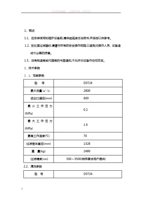
2、技术参数2.1、性能参数型号DST24最大流量(m³/h) 2800进出口通径(mm) 600最小工作压力0.2(MPa)最大工作压力1.6(MPa)最高工作温度(℃) 70过滤筒体直径(mm) 1328重量(kg) 2480过滤精度(µm) 500~3500(特殊要求用户提供)2.2、清洗参数型号DST24排污阀通径65mm清洗时间60秒每次清洗耗水量500升2.3、电控参数型号DST24减速机输出转速14R.P.M、电机功率1.1kw 额定操作电压3相、380V、50HZ控制电压220V AC说明:电控如有特殊要求请在技术协议中提出。
3、制造材质过滤器筒体、端盖碳钢,内涂环氧沥青漆(根据要求可用不锈钢316)滤网不锈钢316L清洗机构不锈钢、PVC排污阀铸铁,环氧树脂涂布密封圈合成橡胶、聚氨脂控制器铝、铜、不锈钢、PVC4、产品结构过滤器由滤筒、滤网、清洗机构、电机减速机、排污阀、压差开关、电控箱等组成,滤网材料为不锈钢,可以清洗。
产品外形尺寸及安装示图(见附图一)5、工作原理水流从过滤器进口流入,经过滤网后从出口流出,杂质颗粒不断地在滤网内表面积聚,滤网内外会产生压力差,当压差达到0.05MPa时,压差开关就会传递电信号到电控箱控制盘,控制盘启动电机,同时打开排污阀,电机带动滤网内部的清洗轴旋转,清洗轴是不锈钢管子,在管子上装有不锈钢丝刷和吸咀。
当清洗轴旋转时,杂质颗粒被转动的刷子从滤网上刷下,然后由吸咀吸入到清洗轴管子中再经排污管和排污阀排出。
6、PLC控制系统说明6.1、自动清洗步骤:(a)排污阀打开;(b)五秒延时;(c)电机减速机启动运转60秒;(d)排污阀和电机减速机关闭停止工作。
使用说明书SMC过滤器 (FGE 系列)FGESA-10(20) , FGELA-10(20)FGESB-10(20) , FGELB-10(20)FGESC-10(20) , FGELC-10(20)SMC株式会社目 录● 安全上的注意・・・・・・・・・・・・・・・・P2 ● 零件名称及功能・・・・・・・・・・・・・・・P3 ● 系统设计,设置,配管・・・・・・・・・・・・・P4 ● 操作・・・・・・・・・・・・・・・・・・・・P4 ● 产品规格・・・・・・・・・・・・・・・・・・P4 ● 滤芯更换和拆卸 ・・・・・・・・・・・・・・P5 ● 本公司主要营业所一览・・・・・・・・・・・・P8FGES,L系列安全上的注意这里所指的注意事项,记载了FGES,FGEL系列产品应如何安全正确的使用,以防止对您及他人造成损伤。
所有与安全相关的重要内容以及其他安全规则,都必须严格遵守。
注意:误操作时,可能造成人及设备的损伤。
警告:误操作时,可能造成人的死亡或重伤。
警告:误操作时,可能会发生漏液或上盖飞出等危险事故。
请有足够知识和经验系统设计者来判断元件的选型是否合适。
使用条件范围操作上的注意①使用压力不要使用超出范围的压力。
②使用温度不要使用超出范围的温度。
③使用流体・禁止使用于气体。
・不要使用于腐蚀性液体。
・不要使用于会引起密封圈,O形圈以及滤芯膨胀或劣化的流体。
④使用环境・不要在有腐蚀性的环境下使用。
・不要在有振动和物体冲击的环境下使用。
①加压状态下禁止松开V形带。
②V形带正确地安装在指定的位置上。
(请参照第7页)③发生膨胀或劣化等异常的O形圈,请进行更换。
O形圈的更换,请在使用后1年以内,或者有漏液发生时进行。
(更换用O形圈:参照3页表1)④泵起动时,请务必将上部的空气排气口打开,进行排气。
⑤请不要使用变形或螺纹破损的V形带。
(更换用V形带:参照3页表1)注意:为防止滤芯破损,保障滤芯的过滤性能及保养点检的可作业性,请务必遵守以下注意事项。
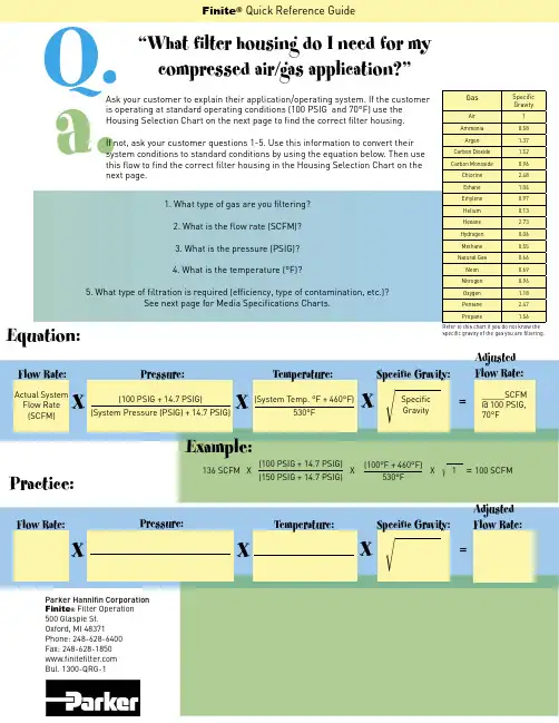
Equation:XFlow Rate:X=X=Practice:XFlow Rate:XPressure:=X=Specifi c GravityActual SystemFlow Rate (SCFM)(100 PSIG + 14.7 PSIG)(System Pressure (PSIG) + 14.7 PSIG)(System Temp. °F + 460°F)530°FTemperature:Pressure:Specifi c Gravity:Q.a.Ask your customer to explain their application/operating system. If the customer is operating at standard operating conditions (100 PSIG and 70°F) use the Housing Selection Chart on the next page to fi nd the correct fi lter housing. If not, ask your customer questions 1-5. Use this information to convert their system conditions to standard conditions by using the equation below. Then use this fl ow to fi nd the correct fi lter housing in the Housing Selection Chart on the next page.1. What type of gas are you fi ltering?2. What is the fl ow rate (SCFM)?3. What is the pressure (PSIG)?4. What is the temperature (°F)?5. What type of fi ltration is required (effi ciency, type of contamination, etc.)?See next page for Media Specifi cations Charts.136 SCFM X(100 PSIG + 14.7 PSIG)(150 PSIG + 14.7 PSIG)(100°F + 460°F)530°FX X 1 = 100 SCFM AdjustedFlow Rate:GasSpecifi cGravityAir 1Ammonia 0.58Argon 1.37Carbon Dioxide 1.52Carbon Monoxide0.96Chlorine 2.48Ethane1.04Ethylene 0.97Helium 0.13Hexane2.73Hydrogen 0.06Methane 0.55Natural Gas 0.66Neon 0.69Nitrogen0.96Oxygen 1.18Pentane 2.47Propane1.56Refer to this chart if you do not know the specifi c gravity of the gas you are fi ltering.Example:Parker Hannifi n Corporation Finite ® Filter Operation 500 Glaspie St.Oxford, MI 48371Phone: 248-628-6400Fax: 248-628-1850www.fi nitefi lter .com Bul. 1300-QRG-1“What fi lter housing do I need for my compressed air/gas application?”Specifi c Gravity:Temperature:Finite ® Quick Reference Guide_____SCFM @ 100 PSIG, 70°FAdjustedFlow Rate:Grade CoalescingEffi ciency0.3 to 0.6MicronAerosolsCoalescingFilters -MaximumOilCarryover1PPM w/wMicronRatingPressure Drop (PSID)@ Rated Flow2MediaDryMediaWet With10-20 wt.Oil499.995%0.0030.01 1.253-4699.97%0.0080.01 1.02-3799.5%0.090.50.250.5 - 0.7898.5%0.20.50.51-1.51095%0.85 1.00.5 1.5100WS N/A N/A100<0.25<0.503P N/A N/A30.25N/AA99%+3N/A N/A 1.0N/A1Tested per ADF-400 at 40 ppm inlet.2Add dry + wet for total pressure drop.3Oil vapor removal effi ciency is given for A media.Grade CoalescingEffi ciency0.3 to 0.6 MicronAerosolsCoalescingFilters -MaximumOil Carryover1PPM w/wMicronRatingPressure Drop (PSID)2@ Rated FlowMediaDryMediaWet With10-20 wt. Oil699.97%0.0080.01 1.5 4.0799.5%0.090.50.250.5898.5%0.50.5 1.0 3.51095%0.85 1.00.75 2.5100WS N/A N/A100<0.25<0.503P N/A N/A30.5N/AA99%+3N/A N/A 1.0N/A1Tested per ADF-400 at 40 ppm inlet.2Add dry + wet for total pressure drop.3Oil vapor removal effi ciency is given for A media.H-Series Media Specifi cation Chart H-Series:ASME Media Specifi cation ChartASME Replacement Element Part Numbers:How to Use the Housing Selection Charts:1. Find the grade your application requires,see Media Specifi cation Chart.2. Locate the grade in the Housing SelectionChart and fi nd your fl ow.3. Find the corresponding Housing Assembly.Grade End Seals Size6810C (Coalescer)Q (Coalescer w/builtin prefi lter)D (High Temp)U (Urethane)For use with C, Q, 3P (standard)S (Silicone)For use with C, Q, D, 3PV (Fluorocarbon)For use with C, Q, D, 3PStandard on 7CVP &100WS, leave thispart blank.Standard on A (AV)51-28085-25085-360To fi nd the sizeyou need, see theReplacementElement Sizecolumn on theASME HousingSelection Chart.3P7CVP100WSAFor example: 6QU51-280; 10DS85-250; 7CVP51-280; AV85-360.Note: _ is a placeholder to put in your port type. N = NPT, S = SAE, F = BSPF, T = BSPTASME Ves sels:HousingAssemblyReplacementElement SizePortSizePort Type NumberofElementsRequiredRated Flows: SCFM @ 100 PSIG (m3/hr @ 7 bar)Grade:6 (Coalescer)A (Adsorber)Grade:8 (Coalescer)Grade:7CVP (PleatedCoalescer)10 (Coalescer)3PU (Interceptor)100WS (WaterSeparator)Line Mount VesselsHT3-80151-2803"NPT11500 (2540)1800 (3050)2490 (4230)FT3-80151-2803"FLANGE11500 (2540)1800 (3050)2490 (4230)FT4-120185-2504"FLANGE12000 (3390)2400 (4070)3320 (5640)FT6-120185-3606"FLANGE13000 (5090)3600 (6110)4980 (8460)FT6-160351-2806"FLANGE34500 (7640)5400 (9170)7470 (12690)Floor Mount VesselsHF3-80151-2803"NPT11500 (2540)1800 (3050)2490 (4230)FF3-80151-2803"FLANGE11500 (2540)1800 (3050)2490 (4230)FF4-120185-2504"FLANGE12000 (3390)2400 (4070)3320 (5640)FF6-120185-3606"FLANGE13000 (5090)3600 (6110)4980 (8460)FF6-160351-2806"FLANGE34500 (7640)5400 (9170)7470 (12690)FF8-180451-2808"FLANGE46000 (10190)7200 (12230)9960 (16920)FF10-220751-28010"FLANGE710500 (17830)12600 (21400)17430 (29610)FF12-301151-28012"FLANGE1116500 (28030)19800 (33640)27390 (46530)FF16-361551-28016"FLANGE1522500 (38220)27000 (45870)37350 (63450)ASME Housing Selection ChartH-Series Housing Selection ChartHousingAssemblyPortSizeRated Flows: SCFM @ 100 PSIG (m3/hr @ 7 bar)Grade:4(Coalescer)Grade:6 (Coalescer)A (Adsorber)Grade7CVP (PleatedCoalescer)Grade:8 (Coalescer)Grade:10 (Coalescer)3PU (Interceptor)100WS (WaterSeparator)H_1S1/4"11 (19)15 (26)N/A20 (34)25 (43)H_15S3/8"15 (26)20 (34)N/A27 (46)33 (56)H_2S1/2"19 (32)25 (43)N/A34 (58)42 (71)H_1L1/4"23 (39)30 (51)N/A41 (68)50 (85)H_15L3/8"30 (51)40 (68)N/A55 (94)66 (112)H_2L1/2"38 (65)50 (85)N/A68 (116)83 (141)H_3S3/4"61 (104)80 (136)N/A109 (185)133 (226)H_4S1"76 (129)100 (170)N/A136 (231)166 (282)H_4L1"106 (180)140 (238)N/A191 (325)232 (394)H_5S 1 1/4"190 (323)250 (425)415 (706)330 (461)415 (706)H_6S 1 1/2"260 (442)350 (595) 600 (1020)465 (791)600 (1020)H_8E2"260 (442)350 (595) 600 (1020)465 (791)600 (1020)H_8S2"340 (578)450 (765) 750 (1275)600 (1020)750 (1275)H_8L2"470 (799)625 (1063) 1035 (1760)830 (1411)1035 (1760)H_0L 2 1/2"600 (1020)800 (1360) 1330 (2261)1060 (1802)1330 (2261)H_12L3"750 (1275)1000 (1700) 1660 (2822)1330 (2261)1660 (2822)*insert selected grade 4, 6, 8, 10. See media specifi cation chart for effi ciencies.HousingAssemblyCoalescer Coalescerw/innerretainerHigh Temp.Coalescerw/built inprefi lter7CVPPleatedCoalescer3PUInterceptor100WS WaterSeparatorAUAdsorberH_1S*C10-025*IU10-025*DS10-025*QU10-025N/A3PU10-025100WSU10-025AU10-025H_15S*C10-025*IU10-025*DS10-025*QU10-025N/A3PU10-025100WSU10-025AU10-025H_2S*C10-025*IU10-025*DS10-025*QU10-025N/A3PU10-025100WSU10-025AU10-025H_1L*C10-050*IU10-050*DS10-050*QU10-050N/A3PU10-050100WSU10-025AU10-050H_15L*C10-050*IU10-050*DS10-050*QU10-050N/A3PU10-050100WSU10-025AU10-050H_2L*C10-050*IU10-050*DS10-050*QU10-050N/A3PU10-050100WSU10-025AU10-050H_3S*C15-060*IU15-060*DS15-060*QU15-060N/A3PU15-060100WSU15-060AU15-060H_4S*C15-060*IU15-060*DS15-060*QU15-060N/A3PU15-060100WSU15-060AU15-060H_4L*C15-095*IU15-095*DS15-095*QU15-095N/A3PU15-095100WSU15-060AU15-095H_5S*CU25-130*CU25-130*DV25-130*QU25-1307CVP25-1303PU25-130100WS25-130AU25-130H_6S*CU25-130*CU25-130*DV25-130*QU25-1307CVP25-1303PU25-130100WS25-130AU25-130H_8E*CU25-130*CU25-130*DV25-130*QU25-1307CVP25-1303PU25-130100WS25-130AU25-130H_8S*CU25-187*CU25-187*DV25-187*QU25-1877CVP25-1873PU25-187100WS25-187AU25-187H_8L*CU25-235*CU25-235*DV25-235*QU25-2357CVP25-2353PU25-235100WS25-235AU25-235H_0L*CU35-280*CU35-280*DV35-280*QU35-2807CVP35-2803PU35-280100WS35-280AU35-280H_12L*CU35-280*CU35-280*DV35-280*QU35-2807CVP35-2803PU35-280100WS35-280AU35-280H-SeriesReplacementElement PartNumbersThis information is aquick reference quide.For more informationsee Finite’s Catalog1300-300/USA.。
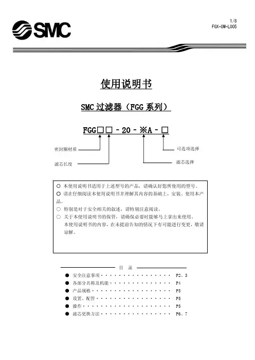
使 用 说 明 书SMC 过滤器(FGG 系列)SMC株式会社目 录 ● 安全注意事项・・・・・・・・・・・・・・・・ P2、3 ● 各部分名称及其作用・・・・・・・・・・・・・・P4 ● 产品规格・・・・・・・・・・・・・・・・・・ P5● 设置、配管・・・・・・・・・・・・・・・・・ P5 ● 操作・・・・・・・・・・・・・・・・・・・・ P5 ● 滤芯的更换方法・・・・・・・・・・・・・・・・P6、7FGG Series/注意事项使用前,请务必阅读。
这里所写的注意事项,目的是使您安全而正确的使用本产品,以便把对给您及他人造成的危害、损害防范于未然。
全部是安全相关的内容,请大家务必遵守。
如果错误操作,引起液体泄漏或防护罩松开,会有意想不到的危险发生。
所以请让有丰富经验及知识的系统设计者来判断。
使用条件警告 ①使用压力请不要在超出压力范围的情况下使用。
②使用温度请不要在超出温度范围的情况下使用。
③使用流体・请绝对不要使用气体。
・请不要使用腐蚀性流体。
・请不要使用对密封圈类、滤芯有膨胀和劣化作用的流体。
④使用环境・请不要在有可能引起腐蚀的环境中使用。
・请不要在存在振动、冲击的场所使用。
操作上的注意事项 警告①在加压的状态下千万不要松开V 型带。
②V 型带请正确设置在指定位置。
(请参考第7页) ③O 型圈若出现劣化、膨胀等异常时请及时更换。
O 型圈从使用即日起1年之后或者发生液体泄漏时要进行更换。
(更换O 型圈请参考第4页表1)④泵启动等加压过程,先开启上部抽气口后必须进行抽气。
⑤不要使用出现变形或螺纹损坏等异常现象的V型带(参考第4页表1)考虑到预防滤芯的破损,确保性能及维修点检的作业性,请务必遵守以下安全注意事项。
设计以及设置上的注意事项警告①使用压力,使用温度,使用流体,使用环境等的 使用条件一定要在制品参数的适合范围内使用。
②压力降(ΔP)请在初期压力降为0.02MPa 以下的流量下使用。
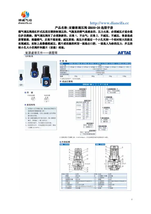
产品名称:亚德客调压阀GR600-20选型手册
煤气调压阀是杠杆式压差反馈控制调压的。
气瓶里的燃气是液态的,压力太高,必须减压才适合通往炉具燃烧。
煤气调压阀坏了必须换新的。
后果1,不出气;后果2,不减压。
不减压,容易造成胶管脱落,泄漏燃气,后果不堪设想。
减压原理:高压介质通过一个小孔充到一个相对较大的腔里实现减压,实际上是靠截流减压。
膜片或活塞的两面一面是出口腔,一面是人为给的压力,并且控制小孔大小的阀杆和膜片(活塞)相连。
标题:亚德客选型电子手册亚德客是全球知名专业生产各类气动器材的大型企业集团,致力于向客户提供满足其需求的气动控制元件、气动执行元件、气源处理元件、气动辅助元件等各类气动器材、服务和解决方案,为客户创造长期的价值和潜在的增长。
亚德客始创于1988年,现辖三大生产基地和一家营销中心,亚德客生产基地厂房面积达37万8千平方米,全球员工总计超过4500人,专业研发技术人员300多人,亚德客选型电子手册总投资1.5亿美元,年生产能力达5,000万件套,产品畅销中国、东南亚、欧美等国家和地区。
亚德客在中国大陆地区拥有近百家直销分公司/营业部,亚德客选型电子手册在全球更是有数千家经销商,主要位于欧洲、美洲及亚洲,形成了完善的销售网络和售后服务体系,可随时为客户提供便捷的服务。
亚德客以拓展集团生产和服务为未来发展的战略目标,坚持走人本优先、改革创新和集团化道路。
秉承“人本、共享、发展、责任”的企业核心价值观,亚德客始终如一地贯彻“以客为尊”的经营理念,始终如一地坚持“以技术创新为核心,亚德客选型电子手册以市场需求为导向”的经营方针,藉以不断完善“建立共好、责任承担、赏罚分明、学习成长”的集团文化,努力奋斗,自强不息,长久致力于全球工业自动化的持续发展。
台湾亚德客工业股份有限公司(简称台亚)成立于1988年11月,前身系健良股份有限公司,1990年更名为台亚。
早期的台亚主要生产电磁阀,此后亚德客选型电子手册陆续研发生产气缸、气源处理等产品。
目前,台亚产品以特殊规格气缸为主,拥有七大类十余系列数百个品种,年产量达到20万件套,主要供应台湾本地市场,满足客户需求及时效性。
1998年,台亚在同行中率先通过“ISO9000质量管理体系认证”;2004年,台亚取得“ISO14000环境体系认证”及“CE认证”。
长期以来,台亚秉持“质量第一、交货准时”的服务精神及理念满足客户需求,亚德客选型电子手册不断引进先进设备、生产工艺提升产品质量与品质。

AGF-6全自动循环水过滤器系统技术说明专业技术用心制造环保节能诚信和谐公司简介:杭州桂冠环保科技,是一家致力于科研、生产、销售水处理设备、过滤设备、水工业阀门的专业生产企业。
公司自创建以来,一贯坚持“依靠科技、严格管理、精心制造、争创一流”的质量方针,贯彻“质量就是效益,质量是企业命脉”的原则。
产品结合以色列过滤技术,专业致力于过滤净化、除垢,系统环保水处理节能产品的开发生产,应用与市场推广的新型企业组织。
我公司拥有雄厚的技术创新力量,技术产业水平高,检测装备全:产品质量性能稳定,工艺精湛。
公司密切接触用户,以求产品质量及售后服务体系与市场完美结合。
公司主要产品有:刷式清洗过滤器、吸式清洗过滤器、全自动浅层式过滤器(全自动循环水旁滤器)、自动清洗盘式过滤器(自动清洗叠片过滤器)、自动反冲排污过滤器、电子水处理仪(除垢仪)、强磁水处理器、离子棒水处理器、全程综合水处理器、旋流除砂器、旁流水处理器、除铁除锰过滤器、AGF浅层介质过滤器、紫外线消毒器、冷凝水回收装置、疏水自动加压装置、阀门等。
杭州桂冠在中央空调、工业循环水、污水、市政、食品、饮用水、反渗透、超滤、农田灌溉及供水管道的应用由于效果显著,节能环保而倍受用户推颂,得到了广泛的应用。
产品销售遍及全国各地,已逐步开始销往香港、台湾、马来西亚、越南等地区国家。
“以人为本,诚信经营,科技创新”,不断提高完善管理水平和售后服务体系,是本企业一贯的坚持,公司一贯奉行“以质量求生存,靠科技求发展”的宗旨。
在全面实施质量管理的基础上,以具有竞争力的成本,提供高品质的产品及优质服务,诚邀中外客商、各界用户和友仁前来考察,愿与您在成功的道路上携手并进,共创辉煌!一、【设备概述】AGF全自动浅层(全自动循环水旁滤器)过滤系统是由多个标准高速砂缸单元组成,其内部设有独特的布水器和集水器,拥有独特的双向自动冲洗阀,可实现在正常系统运行中多个标准高速砂缸逐个单独的反冲洗,全自动程序控制。
亚德客电磁阀选型手册一、简介亚德客电磁阀是一种常用的控制元件,广泛应用于工业自动化领域。
本手册旨在帮助用户了解亚德客电磁阀的选型原则和注意事项,以便正确选择和使用电磁阀,确保系统的正常运行。
二、亚德客电磁阀的分类亚德客电磁阀根据不同的工作原理和控制方式,可以分为以下几类:1.直动式电磁阀:直接由电磁铁控制阀芯的动作,适用于小流量和低压差条件。
2.内导式电磁阀:电磁阀的电磁铁位于阀体内部,通过直接作用于阀芯实现控制。
适用于介质比较脏的场合。
3.外导式电磁阀:电磁铁位于阀体外部,通过阀芯上的铁芯传导磁场来控制阀芯的动作。
适用于高温、高压差和腐蚀性介质的场合。
4.滑阀式电磁阀:阀芯上有滑阀,通过滑阀的相对位移来控制介质的流量。
适用于大流量和高压差条件。
三、亚德客电磁阀的选型原则1.工作压力:根据系统要求确定电磁阀的最大工作压力和最小工作压力范围,在此范围内选择合适的电磁阀。
2.工作温度:了解系统的工作温度范围,选择适合的电磁阀材质和密封材料。
3.介质性质:了解介质的流体性质、腐蚀性、粘度等特性,选择能够适应该介质的电磁阀。
4.电磁阀的控制方式:根据系统的要求,选择适合的控制方式,如直通、单向、双向、常闭或常开等。
5.电磁阀的连接方式:选择适合的连接方式,如螺纹连接、法兰连接等。
6.安全可靠性:根据系统的安全要求,选择可靠性高、寿命长的电磁阀。
7.经济性:根据系统的经济要求,选择性价比最高的电磁阀。
四、亚德客电磁阀的注意事项1.安装位置:电磁阀应安装在易于操作和维护的位置,方便调试和更换。
2.冷却措施:对于长时间工作的电磁阀,应采取散热措施,以防止过热损坏。
3.清洗维护:定期清洗电磁阀,保持清洁,以确保正常工作。
4.电源电压:电磁阀的电源电压应与系统的电源电压匹配,否则会造成电磁阀无法正常工作。
5.操纵方式:根据系统要求选择合适的操纵方式,可以手动、远程或自动控制。
6.驱动方式:根据系统要求选择适合的驱动方式,可以使用直流电磁铁、交流电磁铁或气动驱动。
OPERATION MANUALSMC Filter (FGG series)FGG □□-20-※A-□SMC CorporationINDEX● Safety Instruction ・・・・・・・・・・・・・P2、3 ● Construction ・・・・・・・・・・・・・・・・P4 ● Specification ・・・・・・・・・・・・・・・・P5 ● Installation / Piping ・・・・・・・・・・・・P5 ● Operation ・・・・・・・・・・・・・・・・・P5● Replacement of the element ・・・・・・P6、7Select optionSelect elementElement lengthFGG Series/ Safety InstructionBe sure to read before handling.These safety instructions are intended to prevent a hazardous situation and/or damage to human and equipment by using FGG series properly.Incorrect handling lead to cause fluid leakage or displacement Of the cover which result in unexpected accident..Compatibility of the equipment shall be judged by system designers with knowledge and experience.Cautions shall be followed to avoid element damageand ensure the performance and maintainability.Operating condition rangeDesign and installationWarning① Operating pressure・Do not use pressure exceeding specified range. ② Operating temperature・Do not use where temperature exceeding specified range.③ Operating fluid・Do not use this for gases.・Do not use with corrosive fluid.・Do not use fluid which swell or deteriorates packing, “O” ring or element. ④ Operating environment・Do not use in corrosive environment.・Do not use where exposed to vibration or impact.Caution on operationWarning① Do not loosen V band while pressure is applied.② Install V band correctly to specified position. (See page 7)③ Replace deteriorated or swollen “O” ring.Replace “O” ring in one year after starting use, or fluid leakage occurs.(See page 4 Table 1 :“O” ring for replacement) ④ When supplying pressure for starting the pump,open the relief port to discharge air.⑤ Do not use V band which is deformed or thread is grounded.(See page 4 table 1 : V band for replacement)Warning① Design the system which operating conditionsincluding operating pressure, operating temp., operating fluid, and operating environment shall be appropriate safe operation. ② Pressure drop (ΔP)・Set the flow so that the initial pressure drop is 0.02MPa or less. ③ Space to install・Reserve maintenance space for installation and piping. ④ Flusing・Flush piping line with air before the first usage. ⑤ Prepare air discharge circuit upon necessity.⑥ For high temp. type, protection against burning shall be prepared.⑦ Prepare drain or the circuit to discharge fluid upon necessity.⑧ Use the filter with circuit in which changing loadof the pressure and the flow is small.FGG Series/Safety InstructionBe sure to read before handling.These safety instructions are intended to prevent a hazardous situation and/or damage to human and equipment by using FGG series properly.Maintenance Piping and operation Caution① Foreign matters shall be discharged from drainoutlet.② Replacement of the elementWhen it is the time for replacement of the element,replace with a new element immediately.・The life of element-・ When pressure drop reaches 0.1MPa, replace theelement referring the procedure in this manual.Incorrect handling causes the damage of equipmentand device, and the operation failure.(See Page 6,7 : Replacement of element)③ Cleaning of equipmentWhen replacing the element, clean “O” ting, packingseat surface, the joint part of V band, and thread forsealing properly.④ Surface temp.Confirm that the surface temp. is 40oC or lower whenreplacing the element. For high temp. use, attentionshould be taken to avoid burning.Caution① Ensure the direction of IN/OUT for piping.②Arrange piping so that air discharging work isavailable.③Check each port size for selecting valves andfitting suitable for operating conditions. Flushpiping line with air before operation to check anyproblem including fluid leakage.④Fix the feet to the ground firmly using foundationbolt(M12).⑤ The piping of INLET and OUTLET shall be fixedfirmly to the mounting frame using the saddle sothat load including vibration or weight is notapplied to the piping.⑥ When supplying pressure for starting the pump,ensure opening/closing of piping and connectingparts are completely sealed. If fluid leakage ispresent, stop operation immediately. Investigatethe cause, and replace “O” ring to a new one.Then, tighten the fitting and perform anycorrective action for fluid leakage before restartingoperation.⑦ When supplying pressure for starting the pump,open the relief port(hexagon plug) to discharge air.Release the air(loosen the hex. plug) at the sametime supplying the fluid to substitute air in theproduct by fluid. When air is discharged, close therelief port(tighten the hex. plug) before startingoperation.1. ConstructionFig. 1 Description of parts and functionsTable 1. Description and function of partsNo Description Part number Material Function① Hex. Plug AG-10SSUS304 Plug to release air in the housingJIS B2401-1A-P11 NBR ② “O” ring JIS B2401-4D-P11 FKM “O”ring to seal the cover and hex. plug ③ Wing nut M10×1.5 Class 1SUS304 ④ Washer M10 SUS304 Fix the element retainer⑤ Element retainer- SUS304 Fix the element⑥ Spring AN-3S SUS316WPA Stabilizes the element seal ⑦ Element holder L-27SSUS316 Seals the element ⑧ Element guide U-8S、U-9S、U-10SSUS304 Guides the element ⑨ Tension bolt - SUS304 Shaft fix the element⑩ Element - - Assemble elements into this ⑪ JointJ-4S SUS316 Seal the space between elementAL-25S NBR ⑫ “O” ring AL-22SFKM “O”ring used to seal the sealing part of the cover and the case⑬ V band CY-27S SUS304/SWCH Engage the cover and the case and settle Them⑭ Cover - SUS304 The lid of the product ⑮ Case - SUS304 Main body of the case⑯ Foot- SS400 Support the body(Fix to the ground)⑰ Description on label BH-73S Tetlon ⑱Caution labelBH-77STetlonCautionWhen becomes dirty,replace with anew one(Port size : R2pump.(Port size : G1/8replacing the element.(Port size : R3/4) E N T2. Specifications3. Installation / Piping1)Installation・Fix the feet to the ground firmly using foundation bolt(M12).・Install and arrange piping at the place with enough space for maintenance.2)Piping・Check connect port size to use valves and fitting suitable for operating conditions.・Arrange the piping so that pressure in the product can be released.※Confirm cautions on page 2 and 3 for use.4. Operation1)Operation・Mount V band to specified position. Confirm connecting parts and seal do not leak before start operation.・When starting operation, open upper relief port(loosen hex. plug) to discharge air.2)Replacing the element・Replace the element when pressure drop become lower than specification value.For the replacement of the element, see Replacement of the element on page 6.※Confirm cautions on page 2 and 3 for use.2①Remove the wing nut and the washer.Caution②Remove the element retainer.③Remove the element mount bracket(a part integrating the element holder and the spring).④Take out parts in order of the element, then, joint(element guide).※Caution3① To recycle the micro mesh element and sintered element, eliminate any dust between the end plate and the packing completely.②Mount the element guide if it is removed.③Insert parts in order of the element, joint , element, then, element mount bracket so that they are concentric.Caution④When 2 to 3 elements are placed on top of the other, a set in which the element and joint are prepared can be mounted to the element⑤Assemble the element mount bracket.⑥Mount the element retainer carefully.(1)×Fig. (b)①Mount V band to the collar of the cover and the case correctly. [Refer Fig. (a), (b)Warning②Hit the circumference of V band lightly with plastic hammer for secure mounting.③Mount T bracket to the latch correctly. [See Fig. (c)]④Tighten the clamping nut to specified nut(position from whereinsert the clamping position check pin. [See Fig.(c)]⑤When tightening nut can not be tightened to specified position(position where clamping position check pin can be inserted), replace V band and O ring to new ones. (See table 1).CautionWarningURL Akihabara UDX 15F,4-14-1, Sotokanda, Chiyoda-ku, Tokyo 101-0021,JAPANPhone: +81 3 5207 8249 Fax: +81 3 5298 5362Specifications are subject to change without prior notice and any obligation the part of 2008 SMC Corporation All Rights Reserved。