HP MSA 1000安装及配置手册
- 格式:doc
- 大小:1.33 MB
- 文档页数:10
硬件:服务器:两台hp dl 380g4 ,双cpu ,两块scsi硬盘78g(smart array 6i控制器),做成raid1,hba卡为每台服务器两块qlogic2300,板带双网卡bcm5700光交换机两台 hp storage works 2/8q fiber channel switch5m FC cable x 6msa1000 1个控制器2个。
(右边是主,左边是从),raid1+0,14块硬盘(都是148g)软件:redhat 2.1 (kernel 2.4.9-e3) 惠普带的smartstart cd开始:硬盘做成raid1,可以在开始按f8在bios(是不是叫bios啊,反正台式机里这么叫)里边对两块硬盘做初始化,创建logic分区。
不过最好是用服务器带的smart cd 里边的工具还是很好用的,最好在安装前先看好所带的说明书。
安装linux系统1、硬盘问题因为要与以前的系统兼容,所以需要安装redhat 7.2,后来又换成了2.1,首先就是安装时候系统认不出硬盘,因为服务器只带了for win 和 netware 的驱动(不知道for netware的驱动行不行能不能用,我没试),去惠普的英文网站上下载了for 380G4的smart array 6i 的驱动程序,用rawwrite做成驱动软盘,安装时用 linux dd,成功加载驱动,系统安装成功。
--说明:如果随机带的东西没有你需要的驱动,那么去hp英文网站找驱动吧,那里比较全,很多你在中文网站上是根本就找不到的(鄙视一下,为什么就不把中文支持做的好一些),如果hp网站上没有,可以去板卡的生产厂家去找(比如网卡,hba卡什么的)。
2、网卡驱动网卡是bcm5700,这个可以在bios里边看到的,安装后网卡当然是认不出来了内核太老了,去下载了驱动,结果安装完成后用不了,insmod bcm5700后提示内核版本不对,呵呵,折腾了几次,换了几个版本的驱动尝试(不知道这样会不会有什么潜在的危险),最后,我仔细看了几个驱动的安装说明,最后安装了最正确的版本的驱动程序,(注意:这里我要说的是,仔细阅读安装的说明文件是很重要的,我就是按照上边提示的步骤一步一步去做,最后做成了)安装终于成功。
MS-1000简易操作说明一、特点:1、器材整合过去在连接和调试现场制作系统时,需要耗费大量的时间和劳动力。
而现在通过使用datavideo的MS-1000高/标清移动演播室,即可极大的缩减工作量从而提高工作效率。
现场制作所需的大部分功能,都被集成在一个12U高的航空箱中。
2、视频切换你可最多输入6路视频信号,并在之间进行切换,具有HD/SD SDI及DVI/VGA输入。
除了最常用的CUT(硬切)之外,你还可以应用MIX(叠化)或WIPE(划像)等转场特效。
3、现场录制你可直接将现场制作的节目实时的录制到内置的硬盘录像机中,大容量的250G硬盘可进行长达18个小时的连续录影,并能将素材直接复制至非线性编辑系统进行编辑,省去繁琐的上传采集时间,提高工作效率。
4、通话及Tally提示灯具有最大支持8路的通话系统,采用5芯电缆连接,可同时传输Tally提示灯信号,给摄影师与主持人(被拍摄者)提供当前导播切换机位信息。
5、简易字幕通过DVI接口及亮键功能,可在电脑上直接使用PowerPoint软件预先制作好字幕,叠加在视频上输出。
6、下变换功能内建6组下变换器,可将输入的高清SDI下变换成标清模拟信号进行输出。
二、准备工作:1、设备安装将MS-1000放置于一个平坦、稳固的表面,取下前后面盖。
由于MS-1000内部集成较多器材,发热量比较大,请确保后侧预留足够的空间用于空气流通并方便连接线材。
将3芯的电源线连接至对应的插座上,并确保该插座线路已正常接地。
从机器前面下端拉出切换台,上端拉出监视屏。
2、设备开关机要打开MS-1000,按下机身背面的power电源键,然后依次打开切换台、监视器、通话系统及硬盘录像机的电源。
关闭系统,先依次关闭录像机、通话系统、监视器及切换台,最后按下机器背面的power电源键即可。
3、信号与通道之间的关系你可以将每一个连接到MS-1000的视频信号指派到面板的1-7的通道中的任何一路上。
MSAS1000 多业务接入系统用户手册V2.3©版权所有.北京网新易尚科技有限公司.本文的任何部分,包括文字、例子、表格、插图,未经北京网新易尚科技有限公司事先允许,不得以任何形式或任何手段如电子、机械、手工、光学等,以任何目的再现、传播或翻译。
商标本文中所述及的任何商标或注册商标都属于其所有者。
目录MSAS1000 (1)插图 (IV)1概述 (1)1.1什么是MSAS (1)1.2MSAS的主要特点 (1)1.3MSAS的典型应用 (2)2设备组成 (4)2.1结构说明 (4)2.2单元板说明 (9)2.2.1交换板(MSW) (9)2.2.2电源板(MPW) (9)2.2.3E1接口板(ME1) (9)2.2.4同向64K接口板(MTX) (9)2.2.5FXO接口板(MVO) (9)2.2.6FXS接口板(MVS) (9)2.2.72/4线VF音频接口板(MVF) (9)2.2.8光电板(MOD01/MOD02/MOS) (9)2.2.9电源后插板(MRP02/MRP00) (9)2.2.10用户后插板(MRE/MRT/MRO/MRS/MRF) (9)2.2.11MEE08PDH业务板 (9)3技术指标 (10)3.1工作环境 (10)3.2电源及接地要求 (10)3.3机框尺寸、重量 (10)3.4功耗 (10)3.5E1接口规范 (10)3.6同向64K接口规范 (11)3.7FXO接口规范 (11)3.8FXS接口规范 (11)3.92/4线VF音频接口规范 (11)3.10以太网接口(10Base-T)规范 (11)3.11光接口规范 (12)3.11MEE08E1接口规范(PDH接口规范) (12)4面板指示灯、按键、开关说明 (13)4.1交换板(MSW) (13)4.2电源板(MPW) (14)4.3E1接口板(ME1) (15)4.4同向64K接口板(MTX) (16)4.5FXO接口板(MVO) (17)4.6FXS接口板(MVS) (18)4.72/4线VF音频接口板(MVF) (19)4.8光电板(MOS/MOD01/MOD02) (20)4.9PDH(MEE08)板 (23)5开关跳线设置 (24)5.1电源后插板MRP02开关设置 (24)5.2光电板开关设置 (24)5.3E1板跳线设置 (25)6.1包装方式 (25)6.2安装所需工具 (26)6.3机械安装 (26)6.3.1开包装 (26)6.3.2机框安装 (26)6.3.3用户板安装 (26)6.4电气安装 (27)6.4.1电源后插板连线说明 (27)6.4.2MRE(E1后插板)连线说明 (29)6.4.3MRT(同向64K后插板)连线说明 (30)6.4.4MRO(FXO后插板)连线说明 (31)6.4.5MRS(FXS后插板)连线说明 (32)6.4.6MRF(2/4线VF后插板)连线说明 (33)7故障处理 (34)7.1电源板MPW故障处理 (34)7.2交换板MSW故障处理 (35)7.3E1接口板ME1故障处理 (36)7.4同向64K接口板MTX故障处理 (37)7.5FXS接口板MVS故障处理 (38)7.6FXO接口板MVO故障处理 (39)7.7VF音频接口板MVF故障处理 (40)7.8光电板MOS/MOD01/MOD02故障处理 (41)7.9MEE08故障处理 (41)插图图1-1 MSAS的环网连接 (2)图1-2 MSAS的链状连接 (2)图1-3 MSAS的树状连接 (3)图2-1 MSAS插箱式机框前视图 (5)图2-2 MSAS插箱式机框后视图 (6)图2-3 MSAS壁挂式机框前视图 (7)图2-4 MSAS壁挂式机框后视图 (8)图4-1 MSW面板指示灯、按键、开关说明 (13)图4-2 MPW面板指示灯指示灯、按键、开关说明 (14)图4-3 ME1面板指示灯指示灯、按键、开关说明 (15)图4-4 MTX面板指示灯、按键、开关说明 (16)图4-5 MVO面板指示灯指示灯、按键、开关说明 (17)图4-6 MVS面板指示灯指示灯、按键、开关说明 (18)图4-7 MVF面板指示灯、按键、开关说明 (19)图4-8 MOS面板指示灯、按键、开关说明 (20)图4-9 MOD01面板指示灯、按键、开关说明 (21)图4-10 MOD02面板指示灯、按键、开关说明 (22)图4-11 MEE08面板指示灯、按键、开关说明 (24)图6-1 MRP02连线说明 (27)图6-2 MRP00连线说明 (28)图6-6 MRE连线说明 (29)图6-7 MRT连线说明 (30)图6-8 MRO连线说明 (31)图6-9 MRS连线说明 (32)图6-10 MRF连线说明 (33)表7-1 电源板MPW故障处理 (34)表7-2 交换板MSW故障处理 (35)表7-3 E1接口板ME1故障处理 (36)表7-4 同向64K接口板MTX故障处理 (37)表7-5 FXS接口板MVS故障处理 (38)表7-6 FXO接口板MVO故障处理 (39)表7-7 VF音频接口板MVF故障处理 (40)表7-8 光电板MOS/MOD01/MOD02故障处理 (41)表7-9 MEE08故障处理 (41)1概述1.1什么是MSASMSAS(Multi-Service Assess System)是北京网新易尚科技发展有限公司自主开发研制生产的多业务接入系统。
概要HP StorageWorks Modular Smart Array 1000 (MSA1000)是2 Gb光纖通道儲存系統,專為入門級到中階儲存區域網路(SAN)而精心設計,降低SAN配置的複雜性、費用與風險,是融合系統保護的可延展、高效能儲存系統。
MSA1000的模組化設計讓使用者能夠輕鬆地隨需新增儲存容量。
可擴充至3個HP StorageWorksMSA30磁碟櫃,可容納42個企業級磁碟機,最大儲存容量可達12 TB。
所有必要的架構與管理程式全都內含,在您的容量需求成長或者附掛更多伺服器時,絕無額外授權等額外費用。
MSA1000是HP StorageWorks Modular Smart Array家族的一員,提供業界頂尖技術以滿足當今要求嚴苛而且不斷成長的儲存需求。
這些儲存解決方案提供最佳價格功能比,適用於直接附掛環境、小型叢集與入門級和中階SAN環境。
每一個解決方案都精心設計以發揮最高的傳輸率、降低管理成本,同時提供快速的投資報酬。
異質支援是Microsoft Windows® Server 2003 (32位元與64位元)、Windows 2000、Windows NT®、NetWare與Linux (32位元與64位元)作業系統的標準。
此外,這個韌體還為Tru64 UNIX®或OpenVMS環境中的Alpha伺服器提供獨立支援。
另外,HP擴大MSA1000的作業系統涵蓋範圍,增加在同質環境中的基本HP-UX支援。
主要功能MSA1000提供下列主要功能:●內建於DAS to SAN {DtS}架構的高效能控制器,實現最大的投資保障●4U機架安裝設計,融合控制器與磁碟架● 2 Gb光纖通道主機連線●配合外接式8埠4 Gb光纖通道網絡交換器●支援企業級HP Ultra2、Ultra3與Ultra320通用1"磁碟機●可透過HP StorageWorks磁碟機櫃,從1個延展到42個磁碟機,實現多達12 TB儲存容量●與Hewlett Packard、VERITAS和其他ISV備份與回存軟體相容全新功能●在同質環境中,以運用替代性MSA1000韌體定義的架構,支援業界第一名的UNIX®作業系統HP-UX。
HP MSA1000安装手册一.HPMSA1000的一般硬件配置msa1000因配置如下东西:1.201723-B22 MSA 1000 (光纤磁盘柜,包括以下内容)2.1xMSA1000 控制器/256MB 缓存3.1x容纳14块硬盘机箱4.1xI/O 模块,带有一个2Gb/s SFP接口5.1x通用机柜套件6.2xVHDCI 到 VHDCI SCSI线缆和PDU电源连接线缆7.2x冗余电源和风扇FC Switch SAN322120-B21 MSA Fabric Switch 光纤交换器, 8口外置Servers Connectio:245299-B21 HP光纤通道HBA,支持单机或双机配置( for Windows) 221692-B22 5米LC-LC 多模光纤通道电缆221470-B21 2Gb/s SFP SW Transceive174830-B21 NC3123 10/100 单通道网卡(做心跳侦测)二.HP MSA1000物理连接两台服务器中安装光纤控制卡,将光纤hub插入MSA1000后面,对应阵列控制卡的插槽里,将光纤连接好。
用SCSI线缆将外置的磁盘阵列柜与MSA1000连接.备注: 服务器分别与阵列柜连接(使用2G光纤跳线),特别注意,SAN阵列柜自带一个FC口的模组,另选配了一个2/3 FC HUB 模组 (就是自带带2个FC口,无其它特别之处。
)实际我们只是用2/3 FC HUB 模组连接2台服务器,由于我们SAN 前面板我们只安装了一个控制模块,后面只有一个模组可用(咨询HP工程师得到的答案)所以,请把安装在后面的2/3 FC HUB模组的位置,对着前面控制模组的位置从后面安装进去,这样就可以了,另外一个不可用的模组上的2个灯为黄色闪烁,三.服务器和相关软件的安装(以win2000操作系统为例)(安装系统) 首先在BIOS中选择OS为 windows2000/windows2003,然后用HP服务器自带的 BOOT CD引导服务器,出现图形界面的向导,点击 Setup图标,选择OS类型,选择OS分区大小,选择安装win2kadserver,输入CD-KEY,放入安装光盘,剩下的安装过程就都是自动的了。
安装条件:硬件:两台DS25服务器,MSA1000阵列(带两控制器),四块光纤通道卡(HBA),四条光纤通道线,内存通道卡软件:HP Tru64 5.1B UNIX(带相关补丁)安装步骤:1.硬件连接。
个人认为这是前期的准备工作,是正确安装MSA1000及集群软件的重要前提,如果这个工作没做好,会给后面的工作带来相关的问题,使安装难以继续。
因此,该步工作应该仔细,认真。
硬件连接具体又可以分以下几小步:1)将HBA卡分别安装到DS25服务器上,如果机器本身已带有,恭喜你,这步可以省略。
2)内存通道卡跳线,内存通道卡上有很多跳线器,根据现场的情况应该对内存通道卡进行跳线,具体如何跳,由于现场条件不尽相同,建议参考内存通道卡用户指南。
根据经验,如果这步没做好,再用clu-add-member增加集群节点时会出问题。
3)接线工作。
通过光纤通道线和内存通道卡连接线将HBA卡和阵列,两台服务器之间的内存通道卡正确连接起来。
4)上述工作完成后,可以加电进行下面的操作了。
2.配置MSA1000阵列找一台PC机,通过阵列随机带的黑色串口线(维护线,一端串口,一端RJ45口),将PC 机和阵列的控制器连接起来。
在PC中,通过超级终端和阵列通讯,其中,串口的设置为:波特率: 19200数据位: 8奇偶校验: 无停止位: 1流控制: 无在阵列启动完成后,在超级终端下敲回车键,会看到CLI> 提示符在该提示符下,可以对磁盘阵列进行配置了。
(以做RAID 5为例)1)首先查看阵列中的硬盘CLI> show disksDisk List: (box,bay) (bus,ID) Size UnitsDisk101 (1,01) (0,00) 72.8GB noneDisk102 (1,02) (0,01) 72.8GB noneDisk103 (1,03) (0,02) 72.8GB noneDisk104 (1,04) (0,03) 72.8GB noneDisk105 (1,05) (0,04) 72.8GB none2)对阵列进行分区一般的分区原则,若是集群中只有两个节点,则分五个盘:unit 1 Quorum盘,它是一个可以被两个节点访问的物理硬盘,用来保存集群的信息。
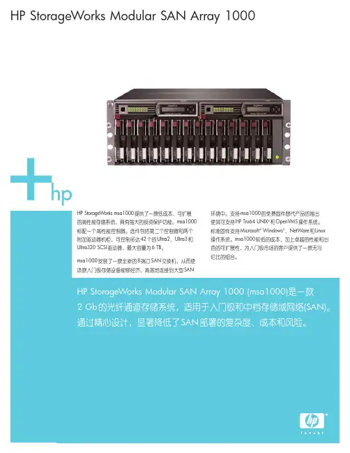
HP StorageWorks Modular SAN Array 1000HP StorageWorks msa1000提供了一款低成本、可扩展的高性能存储系统,具有强大的投资保护功能。
msa1000标配一个高性能控制器。
选件包括第二个控制器和两个附加驱动器机柜,可控制多达42个的Ultra2、Ultra3和Ultra320 SCSI 驱动器,最大容量为6 TB 。
msa1000安装了一款全新的8端口SAN 交换机,从而使该款入门级存储设备能够经济、高效地连接到大型SAN环境中。
支持msa1000的免费固件替代产品的推出使其可支持HP Tru64 UNIX ®和OpenVMS 操作系统。
标准固件支持Microsoft ®Windows ®、NetWare 和Linux 操作系统。
msa1000较低的成本,加上卓越的性能和出色的可扩展性,为入门级市场的客户提供了一款无与伦比的组合。
HP StorageWorks Modular SAN Array 1000 (msa1000)是一款2 Gb 的光纤通道存储系统,适用于入门级和中档存储域网络(SAN)。
通过精心设计,显著降低了SAN 部署的复杂度、成本和风险。
2HP StorageWorks Modular SAN Array 1000•推出的内嵌式交换机选件的特性和功能进一步增强•可与大多数惠普外部存储局域网交换机连接并实现完全互操作,且价格较低;即使在冗余配置中也无需更多机架空间•更出色的固件,支持HP Tru64 UNIX 和OpenVMS 操作系统•灵活:支持Windows 2000和NT 、NetWare 、Linux,或Tru64 UNIX 和OpenVMS 操作系统•性能:传输速率高达30K I/Ops (高速缓存),吞吐率高达200 MB•兼容:在4U 机架空间内安装了14个1英寸驱动器,1 Gb 或2 Gb 结构交换机或集线器•可扩展:使用42个146 GB 硬盘驱动器,可在10U 的机架空间内轻松扩展至6 TB •集成:允许在内部安装可选的MSA 8端口交换机,或HP StorageWorks msa 集线器2/3•可维护:支持热插拔驱动器、控制器、风扇、电源、交换机和集线器•可靠:支持最高的容错级别(RAID ADG)新特性主要特性与优点技术规格HP StorageWorks Modular SAN Array 1000msa1000正面状态指示灯(3个)•电源•检测一个或多个子系统故障•机柜管理故障驱动器模块状态指示灯(3个)•驱动器访问(中心)•在线(左边)•驱动器故障(右边)后面板上的状态指示灯(4个)•电源/鼓风机组件故障(1个)•EMU (3个)电源,a总线,b总线接口•Ultra3 SCSI到硬盘驱动器•2Gb光纤通道到主机最大驱动器数14个1英寸Ultra2、Ultra 3或Ultra320通用驱动器(msa1000机箱);使用两个附加HP StorageWorks 4200/4300机柜可扩展至42个温度范围工作:50°到95°F/10°到35°C装运:–22°到122°F/–30°到50°C注释:10,000英尺中每上升1,000英尺要降低1∞C相对湿度:工作:10%到90%非工作:高达95%输入电源要求额定输入电压:100到240伏,交流电额定输入频率:50到60赫兹额定输入电流:最大6安培输入电源(最大):549瓦*散热(最大)1876 BTU/小时*msa1000机箱4U机架外形外形尺寸(高×宽×长): 6.9×19×20.5英寸/17.5×48.3×52.1厘米重量:净重55到85磅/25.0到38.6千克装运包装外形尺寸(高×宽×长):28.5×14.81×33.13英寸/72.4×37.6×84.2厘米重量:总重75到105磅/34.0到47.6千克技术规格-续msa SAN switch 2/8光纤通道端口8个通用端口(1个内部,7个外部。
产品概述
HP StorageWorks模块化智能阵列(MSA)家族采用简单、经济、业界领先的技术,提供卓越的存储性能,同时增强投资保护
HP StorageWorks Modular Smart Array 1000 (MSA1000)是一个2 Gb光纤通道存储系统,为直连环境、小型集群及入门级和中档SAN环境提供性价比最佳的特性。
每款解决方案均具备最大传输率,可在降低管理成本的同时,加快投资回报。
MSA1000是一个可扩展的高性能存储系统,它降低了部署SAN的复杂性、费用及风险,其模块化的设计允许您按照需要来增加存储容量。
它增加了2个HP StorageWorks MSA30磁盘机柜,具备42个企业级驱动器的集合空间,因而最大存储容量可达到6 TB。
随着您的容量需求不断提高,或者连接了更多的服务器时,该解决方案中包含了所有配置和管理程序,而且无需支付预料之外的费用来购买额外许可。
MSA1000是Microsoft Exchange服务器、文件和打印任务、以及中小数据库应用的理想选择
主要特性与优点
∙在DAS到SAN (DtS)架构上建立高性能控制器:快速、轻松地迁移由大部分智能阵列控制器所保护的存储数据
∙提供广泛的操作系统支持:包括Microsoft Windows、HP-UX、Linux、
NetWare、OpenVMS和Tru64 UNIX
∙支持广泛的服务器选择:支持32位和64位HP ProLiant及Integrity动能机型以及AlphaServer系统和众多工业标准x86设备∙具备集成配置和管理工具:利用集成的标准管理和实用软件
∙利用MSA30机柜扩展容量
技术规格:。
概要HP StorageWorks Modular Smart Array 1000 (MSA1000)是2 Gb光纖通道儲存系統,專為入門級到中階儲存區域網路(SAN)而精心設計,降低SAN配置的複雜性、費用與風險,是融合系統保護的可延展、高效能儲存系統。
MSA1000的模組化設計讓使用者能夠輕鬆地隨需新增儲存容量。
可擴充至3個HP StorageWorksMSA30磁碟櫃,可容納42個企業級磁碟機,最大儲存容量可達12 TB。
所有必要的架構與管理程式全都內含,在您的容量需求成長或者附掛更多伺服器時,絕無額外授權等額外費用。
MSA1000是HP StorageWorks Modular Smart Array家族的一員,提供業界頂尖技術以滿足當今要求嚴苛而且不斷成長的儲存需求。
這些儲存解決方案提供最佳價格功能比,適用於直接附掛環境、小型叢集與入門級和中階SAN環境。
每一個解決方案都精心設計以發揮最高的傳輸率、降低管理成本,同時提供快速的投資報酬。
異質支援是Microsoft Windows® Server 2003 (32位元與64位元)、Windows 2000、Windows NT®、NetWare與Linux (32位元與64位元)作業系統的標準。
此外,這個韌體還為Tru64 UNIX®或OpenVMS環境中的Alpha伺服器提供獨立支援。
另外,HP擴大MSA1000的作業系統涵蓋範圍,增加在同質環境中的基本HP-UX支援。
主要功能MSA1000提供下列主要功能:●內建於DAS to SAN {DtS}架構的高效能控制器,實現最大的投資保障●4U機架安裝設計,融合控制器與磁碟架● 2 Gb光纖通道主機連線●配合外接式8埠4 Gb光纖通道網絡交換器●支援企業級HP Ultra2、Ultra3與Ultra320通用1"磁碟機●可透過HP StorageWorks磁碟機櫃,從1個延展到42個磁碟機,實現多達12 TB儲存容量●與Hewlett Packard、VERITAS和其他ISV備份與回存軟體相容全新功能●在同質環境中,以運用替代性MSA1000韌體定義的架構,支援業界第一名的UNIX®作業系統HP-UX。
MAX-1000 矩阵系统用户手册HONEYWELL Co,. Ltd.目录1.综述1.1 简介1.2 CCTV键盘1.3 模拟操作面板1.4 其它设备1.5 本手册所作的前提假定1.6 本手册所用的惯例击键数字范围注意要点监示器信息1.7 厂商联络方式1.8 商标注明2 启动2.1 输入你的选择号码,怎样和为什么?2.2 监示器选择2.3 摄像机选择2.4 PTZ摄像机控制2.5 VCR选择2.6 CCTV键盘控制VCR2.7 摄像机录像2.8 辅助装置和复用器3 扫描序列的使用3.1 什么是扫描序列?什么是扫描序列3.2 启动扫描序列3.3 中止扫描序列3.4 暂停扫描序列3.5 产生新的扫描序列3.6 扫描序列的编辑用新的摄像机选择进行替换删除该摄像机选择插入新的摄像机选择3.7 改变停顿周期3.8 为一个摄像机增加停顿4 宏语言的使用4.1 什么是宏程序?齐投摄像机选择摄像机漫游自动控制4.2 宏语言的执行4.3 产生一个新的宏程序4.4 宏程序的删除4.5 我能编辑一个宏程序吗?5 警报管理5.1 什么是警报?5.2 外部警报输入5.3 摄像机故障警报视频丢失低电平视频5.4 PTZ解码箱故障警报5.5 PTZ解码箱防拆警报5.6 VCR警报5.7 其它装置警报5.8 警报堆栈5.9 在警报堆栈上移位5.10 清除警报6 键盘的其它功能6.1 快速摄像机选择6.2 设置摄像机视场(PTZ预置位) 6.3 调用摄像机视场(PTZ预置位) 6.4 摄像机PTZ复位6.5 选择代用摄像机6.6 隐藏显示的字符6.7 显示SMARTEXTTM7 菜单系统7.1 什么是菜单系统?访问菜单系统退出菜单系统7.2 从菜单上选择移动菜单进入窗口7.3 键盘操作员登记7.4 键盘操作员注销7.5 激活/中止视频输入中止一个摄像机激活一个摄像机7.6 锁定/释放视频输入控制锁定一个PTZ摄像机释放一个PTZ摄像机锁定/释放一个PTZ摄像机7.7 锁定/释放视频输出选项锁定视频输出选项释放视频输出选项锁定/释放视频输出选项7.8 中止/激活警报输入中止警报输入激活警报输入9.3 字符显示定时9.4 监示器黑屏9.5 黑屏暂停9.6 监示器访问9.7 操作员对系统的访问9.8 操作员的级别划分9.9 CCTV键盘定时9.1 0 自动注销9.11 摄像机故障检测视频丢失低电平视频1 0 排除提示10.1 摄像机选择第一章概述1.1简介MAX一1000 CCTV管理系统是一个强功能的计算机控制视频切换矩阵。
MSA1000连接RX1600(HP-UX)安装7月中旬,根据用户的需求,在西宁电信安装MSA1000。
以下是安装的大致过程。
回顾安装过程,其实在刚开始就走了几个弯路。
【用户现场环境】在MSA1000安装之前,用户的存储是RX1600直连VA7110,所用的光纤是SC-LC。
操作系统为HP-UX11.23.拆开MSA1000的外包装,感觉体积不大,不过有点沉,所以在搬动MSA1000等存储的时候最好有两个人。
MSA1000的配置是 HUB 2/3,reduancy controller.由于MSA存储产品并非HP嫡系产品,用在HP-UX 平台下的很少,支持也相对较少,只是到了后期的一些版本才支持HP-UX。
其主要作为中小型企业的中低端SAN存储。
将RX1600和VA先后shutdown,更换RX1600与VA7100的SC-LC的光纤为LC-LC光纤。
先后启动MSA1000和RX1600后,ioscan根本无法看到MSA1000的设备。
在启动和dmesg信息中出现如下提示:0/2/1/0: WARNING: It appears that there are (or were) more than one device withthe same address (nport ID) setting of 0x0. One of them will be ignored.#fcmsutil /dev/td0 replace_dsk 0x0Failure in ioctl: No such device or address#fcmsutil /dev/td0 replace_dsk 0x000002Disk at nportid 0x000002(Loop_id 124) will not be authenticatedioscan仍无法查看到MSA1000设备,重启机器也始终无法解决,且上述信息仍旧发生。
HP存储MSA配置步骤和状态监控MSA是HP低端存储产品,是Modular Smart Array的缩写,我们用到的MSA系列产品有MSA20、MSA30、MSA1000和MSA1500。
MSA20和MSA30只是个傻盘柜,没有raid 功能,直接连到主机,如要配置raid则需要在主机上安装raid卡。
MSA1000/1500是盘柜加控制器,控制器可管理、配置raid,控制器外部接2Gb光纤到主机,需要主机配有HBA卡(光纤卡)。
MSA1500支持冗余路径,可保证数据的安全。
下面简单的讲解了MSA现场的配置过程和MSA远程在线的配置方法。
一、MSACLI配置步骤1配置准备:1.1主机光纤卡正确安装并与MSA控制器连接1.2MSA硬件安装完毕1.3请确认MSA控制器firmware版本为6.86或更高(仅针对配置双控负荷均担)2配置步骤:2.1配置前的准备工作2.1.1查看HP-UX主机HBA卡WWPN号用root用户登录主机,键入如下命令:(以实验室设备benz为例)root@benz:/>ioscan -fnC fcClass I H/W Path Driver S/W State H/W Type Description=================================================================fc 0 0/4/1/0 td CLAIMED INTERFACE HP Tachyon XL2 Fibre Channel Mass Storage Adapter/dev/td0root@benz:/>fcmsutil /dev/td0V endor ID is = 0x00103cDevice ID is = 0x001029XL2 Chip Revision No is = 2.3PCI Sub-system Vendor ID is = 0x00103cPCI Sub-system ID is = 0x00128cTopology = PTTOPT_FABRICLink Speed = 2GbLocal N_Port_id is = 0x010100N_Port Node World Wide Name = 0x50060b00005fc129N_Port Port World Wide Name = 0x50060b00005fc128Driver state = ONLINEHardware Path is = 0/4/1/0Number of Assisted IOs = -1536164319Number of Active Login Sessions = 1Dino Present on Card = NOMaximum Frame Size = 2048Driver Version = @(#) libtd.a HP Fibre Channel TachyonTL/TS/XL2 Driver B.11.11.12 PATCH_11.11 (PHSS_31326) /ux/kern/kisu/TL/src/common/wsio/td_glue.c: Sep 5 2005, 10:14:40注意上面红色的号码,在MSA配置中的格式为:50060b00-005fc1282.1.2查看Linux主机HBA卡WWPN号用root用户登录主机,键入如下命令:(以实验室设备jetta为例)[root@jetta ~]# cat /proc/scsi/qla2xxx/0QLogic PCI to Fibre Channel Host Adapter for QLA2340:Firmware version 3.03.18 IPX, Driver version 8.01.02-d4ISP: ISP2312, Serial# D08964Request Queue = 0x37640000, Response Queue = 0x37630000Request Queue count = 2048, Response Queue count = 512Total number of active commands = 0Total number of interrupts = 160Device queue depth = 0x10Number of free request entries = 2047Number of mailbox timeouts = 0Number of ISP aborts = 0Number of loop resyncs = 0Number of retries for empty slots = 0Number of reqs in pending_q= 0, retry_q= 0, done_q= 0, scsi_retry_q= 0Host adapter:loop state = <DEAD>, flags = 0x1a03Dpc flags = 0x4000000MBX flags = 0x0Link down Timeout = 008Port down retry = 016Login retry count = 016Commands retried with dropped frame(s) = 0Product ID = 4953 5020 2020 0002SCSI Device Information:scsi-qla0-adapter-node=200000e08b84e4b6;scsi-qla0-adapter-port=210000e08b84e4b6;FC Port Information:SCSI LUN Information:(Id:Lun) * - indicates lun is not registered with the OS.若要查看主机上的第二快HBA卡,命令为cat /proc/scsi/qla2xxx/12.1.3查看AIX主机HBA卡WWPN号用root用户登录主机,键入如下命令:(以湖南SCP11A为例)root@SCP11A>lsattr -El dac0GLM_type low GLM type Falsealt_held_reset no Alternate held in reset Falsecache_size 128 Cache Size in MBytes Falsecontroller_SN 1T54396785 Controller serial number Falsectrl_type 1722-600 Controller Type Falselocation Location Label Truelun_id 0x0 Logical Unit Number Falsenode_name 0x200800a0b81f56e8 FC Node Name Falsepassive_control no Passive controller Falsescsi_id 0x10000 SCSI ID Falseutm_lun_id 0x001f000000000000 Logical Unit Number Falseww_name 0x200900a0b81f56e9World Wide Name False注意上面红色的号码,在MSA配置中的格式为:200900a0-0b81f56e92.1.4连接MSA控制器方法:找一台PC机,通过阵列随机带的黑色串口线(维护线,一端串口,一端RJ45口),将PC机和阵列的控制器连接起来。
1. 首先要确保在 MSA1000 的第一个控制器插槽按装一个控制器2 . 使用串口线将主机与控制器相连3. 设置超级终端连接a. Access HyperTerminal.b. Open HyperTerminal.如果是第一次访问,将会出现一个新建对话框,如下图 . See Figure 1 for an example of the New Connectiondialog box.c. 输入连接名,点击OK .The Connect To dialog box is displayed.See Figure 2 for an example of the Connect To dialog box.d. 在上面的对话框里,点击 Connect Using 下拉菜单,选择正确的端口。
会出现如下图所示的端口属性对话框,Figure 3 is an example of the COM1 Properties dialog box.e. 在上面的对话框里,设置正确的值,如下所示,点击OK .Bits per Second: 19200Data bits: 8Parity: NoneStop bits: 1Flow control: NoneThe CLI input screen is displayed.f. 在出现的 CLI 窗口里点击回车键,会出现 cli> 提示符,此时可以输入配置命令了下面介绍一些常用的命令创建逻辑驱动器 Creating LUNs基本命令 Basic commandADD UNIT命令参数选项 Command optionsDATA=“DISKzzz” —the number of an individual drive to incorporate into theLUN. Disks are identified by box number and bay number. For example,DISK110 identifies disk 10 in box number 1.DATA=“DISKxxx-DISKyyy” —a range of drives is to be incorporated into theLUN. Disks are identified by box number and bay number. For example,DISK101-DISK105 identifies disks 1 through 5 in box number 1.Note: Quotation marks must be entered both before and after the data disk drives thatare to be included in the LUN.RAID_LEVEL= xxx —the RAID fault-tolerance level to use, where xxxrepresents:0 = RAID 0 (no fault tolerance)1 = RAID 1 (mirroring)5 = RAID 5 (distributed parity)ADG = Advanced Data Guarding (ADG)Note: If more than one pair of drives are included in a RAID 1 array, the data isstriped across the first half of the drives in the array and then each drive is mirrored to adrive in the remaining half of the drives for faulttolerance. This method is referred to asRAID 1+0.STRIPE_SIZE= xxx —(optional) the stripe size to assign (in KB), where xxxrepresents 8, 16, 32, 64, 128, or 256 Kilobytes.RAID 0 uses stripe sizes 8, 16, 32, 64, 128, and 256 (Default: 128 KB)RAID 1 uses stripe sizes 8, 16, 32, 64, 128, and 256 (Default: 128 KB)RAID 5 uses stripe sizes 8, 16, 32, and 64 (Default: 16 KB)RAID ADG uses stripe sizes 8, 16, 32, and 64 (Default: 16 KB)SIZE= xxxxyy —(optional) how much of the available space on the indicateddrives is to be used for the LUN, where xxxx represents the LUN size and yyindicates MB or GB. (When GB is entered, all return displays will beconverted to MB.) If no size is specified, the maximum available space of theincluded disks will be assigned to the unit. See “Creating Multiple LUNs on aGroup of Drives” for an example of using the Size command option.SPARE=DISKxxx —(optional) disk(s) to assign as a spare to the unit, wherexxx represents the disk number. More than one disk can be assigned as aspare to a LUN.MAXBOOT=ENABLE/DISABLE —(optional) changes the size of the boot partition.Enable = 8-GB boot partition (default)Disable = 4-GB boot partitionCACHE=ENABLE/DISABLE —(optional) determines whether to use the arraycontroller cache for the LUN.Enable = (default) use the array controller cacheDisable = not use the array controller cacheCreating a single LUN from a group of drivesTo create one LUN from an individual drive or group of drives:Example commandCLI> ADD UNIT 0 DATA=”DISK101-DISK107 DISK110” RAID_LEVEL=ADGSTRIPE_SIZE=64Note: Maintain a record of the units as they are created. These Unit ID numbers areused in other CLI commands. In addition to recording the unit number, the drivesincluded, RAID type and size, record the order in which they are created .Command options0 —LUN 0 is to be created.DATA=”DISK101-DISK107 DISK110” —drives 1 through 7 and disk 10 in boxnumber 1 are to incorporated into the LUN.RAID_LEVEL=ADG —RAID level ADG will be used when creating LUN 0.STRIPE_SIZE=64 —stripe size of 64 will be used when creating LUN 0.Example CLI responseFirst volume to be configured on these drives.Logical Unit size = 69460 MBRAID overhead = 0 MBTotal space occupied by new unit = 69460 MBFree space left on this volume = 0 MBUnit 0 is created successfully.创建多个逻辑驱动器 Creating Multiple LUNs on a group of drivesTo carve out multiple LUNs from a drive or group of drives, use the ADD UNITcommand and include the SIZE= command option. Repeat the command using aunique LUN ID for each LUN, along with the desired size parameter.Example commandCLI> ADD UNIT 1 DATA=”DISK111-DISK114”RAID_LEVEL=5STRIPE_SIZE=32 SIZE=1000MBNote: Maintain a record of the units as they are created. These Unit ID numbers areused in other CLI commands. In addition to recording the unit number, the drivesincluded, RAID type and size, and record the order in which they are created .Command options1 —LUN 1 is to be created.DATA=”D ISK111-DISK114” —drives 11 through 14 in box number 1 to theLUN.RAID_LEVEL=5 —RAID 5 will be used when creating the LUN.STRIPE_SIZE=32 —stripe size of 32 will be used when creating the LUN.SIZE=1000MB —1000 MB of the available space will be used for the LUN.Example CLI responseThe following display is a continuation of the previous example, creating threeLUNs on the same group of physical drives.CLI> ADD UNIT 1 DATA=”DISK111-DISK114”RAID_LEVEL=5STRIPE_SIZE=32 SIZE=1000MBFirst volume to be configured on these drives.The logical unit size has been adjusted by 4MB for optimalperformance.Logical Unit size = 996 MBRAID overhead = 498 MBTotal space occupied by new unit = 1494 MBFree space left on this volume = 24533 MBUnit 1 is created successfully.CLI> ADD UNIT 2 DATA=”DISK111-DISK114”RAID_LEVEL=5STRIPE_SIZE=32 SIZE=2000MBLogical Unit size = 2000 MBRAID overhead = 1000 MBTotal space occupied by new unit = 3000 MBFree space left on this volume = 21533 MBUnit 2 is created successfully.CLI> ADD UNIT 3 DATA=”DISK111-DISK114”RAID_LEVEL=5STRIPE_SIZE=16 SIZE=4000MBLogical Unit size = 4000 MBRAID overhead = 2000 MBTotal space occupied by new unit = 6000 MBFree space left on this volume = 15533 MBUnit 3 is created successfully.创建带指定 spare 的逻辑驱动器 Creating a LUN with an assigned spareTo create a LUN and assign a spare at the same time, use the ADD UNIT commandand include the SPARE= command option.Note: More than one spare can be assigned to the same LUN and the same spare canbe available to multiple LUNs.Example commandCLI> ADD UNIT 4 DATA=”DISK211-DISK212”RAID_LEVEL=1SPARE=”DISK213”Note: Maintain a record of the units as they are created. These Unit ID numbers areused in other CLI commands. In addition to recording the unit number, the drivesincluded, RAID type and size, and record the order in which they are created .Command options4 —LUN 4 is to be created.DATA=”DISK211-DISK212” —drives 11 through 12 in box number 2 are to beincorporated into the LUN.RAID_LEVEL=1 —RAID 1 will be used when creating the LUN.SPARE=”DISK213” —the drive in bay 13 of box 2 will be assigned as a sparedrive to the LUN.Note: Quotation marks must be entered both before and after the disk drive that is tobe designated as a spare for the LUN.Example CLI responseFirst volume to be configured on these drives.Logical Unit size = 69460 MBRAID overhead = 69460 MBTotal space occupied by new unit = 138920 MBFree space left on this volume = 0 MBUnit 4 is created successfully.给逻辑驱动器指定名字或 ID-Assigning a name or ID to a LUNIf desired (or required by your operating system), each LUN can be assigned aunique name or ID in addition to its number. These user-defined names make iteasier to identify specific LUNs in other configuration procedures.Note: OpenVMS systems require each LUN to have a unique ID. No two devices in theentire SAN for this OpenVMS system may share ID numbers. LUNs in different storagesystems must have different IDs.Basic commandSET UNIT_IDExample commandCLI> SET UNIT_ID 0 ABCCommand options0 — LUN 0 is being assigned a name .ABC — is the name to assign to LUN 0. The name of this LUN will be ABC .Example CLI responseIdentifier “ABC” created for unit 0添加一个 SPARE 盘 -Adding a spare to a LUNTo add a spare to an existing LUN:Basic commandADD SPAREExample commandCLI> ADD SPARE UNIT=2 DISK109Command optionsUNIT=2 —the unit to assign the spare to. This is the same number that wasgiven to the unit when it was created with the ADD UNIT command. In thisexample, LUN 2 will have use of the spare.DISK109 —indicates the drives to assign as the spare to the LUN. Disks areidentified by box number and bay number. In this example, drive 9 in boxnumber 1 is to be used.Example CLI responseFirst volume to be configured on these drives.Logical Unit size = 69460 MBRAID overhead = 69460 MBTotal space occupied by new unit = 138920 MBUnit 2 is created successfully.删除一个逻辑驱动器 -Deleting LUNsTo delete the last created LUN:Note: If more than one LUN has been created, only the last LUN created can bedeleted. It is important to maintain a record of the unit numbers and the order in whichthey are created.Note: After a LUN is deleted, its unit number goes unused until manually assigned to anew LUN. Unit numbers are not automatically reassigned when a LUN is deleted.Basic commandDELETE UNITExample commandCLI> DELETE UNIT 4Command options4 —the unit to delete. This is the same number that was given to the unit whenit was created with the ADD UNIT command. In this example, LUN 4 is to bedeleted.Example CLI responseData will be lost after the unit is deleted.Do you still want to DELETE unit 4 (Y/N)? YPlease wait while unit 4 is being deleted…Unit 4 is deleted successfully.删除 sparesTo remove a spare from use:Basic commandDELETE SPAREExample commandCLI> DELETE SPARE UNIT=2 DISK109Command optionsUNIT 2 —the unit that will no longer have access to the spare. This is the samenumber that was given to the unit when it was created with the ADD UNITcommand. In this example, LUN 2 will no longer have access to the spare.DISK109 —the spare drive to remove from use. Disks are identified by boxnumber and bay number. In this example, drive 1 in box number 9 will nolonger be used as a spare for LUN 2.更改失败的逻辑驱动器的状态 -Recognizing a failed unitIf all drives of a previously failed unit are in working order, use this command tochange the state of the unit back to VOLUME_OK .To accept media exchange on a unit marked as failed:Basic commandACCEPT UNITACCEPT UNITSExample commandCLI> ACCEPT UNIT 2Command options# —the unit that you want to activate, where # represents the unit number.If a unit number is not specified, all units will be reset.修改逻辑驱动器 --Modifying arrays and LUNsOccasionally, after an array or a LUN has been created, its characteristics need tobe changed. The following changes can be made:■ Adding drives to an array■ Adding space to a LUN■ Changing the RAID characteristics of a LUN■ Changing attributes of a LUNEach task is discussed in the following paragraphs.Adding drives to an arrayTo add additional physical drives to an array:Note: Because this command affects the entire array, all LUNs made from the array arealso affected.Basic commandEXPAND UNITExample commandCLI> EXPAND UNIT 4 DISK204-DISK207Command options4 —one of the LUN within the target array.Note: Any LUN in the array can be entered to identify the array; the space is added tothe array and not the LUN.DISK204-DISK207 —the physical disks to add to the array. Disks are identifiedby box number and bay number. In this example, DISK204-DISK207 identifiesdisks 4 through 7 in box number 2.Example CLI responseThe actual new array capacity will be 3000MB.The array with Unit 4 is being expanded.Use “show unit 4” to monitor progress.给逻辑驱动器添加 SPARE-Adding space to a LUNTo add unused, available space in an array to a specific LUN:Basic commandEXTEND UNITExample commandCLI> EXTEND UNIT 2 ADD_SIZE=1000MBCommand options2 —the LUN to which the space will be added. In this example, LUN 2 isbeing extended.ADD_SIZE=1000MB —how much of the available space in the array to add to theLUN. In this example, 1000 MB of space will be added. The size limit mustbe specified as GB, MB, or KB. If no size is specified, the maximum availablespace of the included disks will be assigned to the array.NEW_SIZE= xxxxyy —can be used instead ofADD_SIZE to enter the total newsize of the LUN, where xxxx represents the size and yy indicates GB, MB, orKB.Example CLI responseThe actual new volume size will be 1992MB.Unit 2 is being extended.Use “show unit 2” to monitor progress.改变逻辑驱动器的参数 -Changing attributes of a LUNTo enable or disable the array accelerator cache for a specific LUN:Basic commandSET UNITExample commandCLI> SET UNIT 0 CACHE=DISABLECommand optionsUNIT 0 —the number of the LUN to modify. In this example, LUN 0 will bemodified.CACHE=ENABLE or DISABLE —either enables or disables the use of the arrayaccelerator cache for the specified LUN.Example CLI responseCLI> SET UNIT 0 CACHE=ENABLECache for unit 0 has been enabled.CLI> SET UNIT 1 CACHE=DISABLECache for unit 1 has been disabled.使盘柜与服务器相连 -Server connection commandsEach time the MSA is powered on, all active HBA connections to the MSA areautomatically detected and identified by their WWPN.Before a server accesses the storage of the MSA, you must identify the operatingsystem (host mode) of each connection. HP also recommends assigning auser-defined name to each connection, to make the identification and setup of eachconnection easier.After connections are established, be sure to restrict access to the LUNs to specificservers. The CLI uses an Access Control List (ACL) to enter the list of LUNs aserver can access. See the following section “ Access control list commands” formore information about SSP and ACLs.Each of the following commands is used to enter and manage the connections:■ Naming a connection■ Setting the connection profile■ Changing the name of a connection■ Changing the HBA of a connection■ Deleting a connection nameNote: Use the SHOW CONNECTIONS command to display information about each HBAconnected to the MSA, including connection name, WWPN, and profile.The connection name and the WWPN are used when entering connection information.See “Viewing connection information” on page 30 fordetails.给连接命名 -Naming a connectionThis command is used to name the association between the Fibre Channel Initiator(HBA in the server) and the MSA, while at the same time identifying theoperating system (connection profile) of the server. The name given to aconnection is user defined, according to a naming convention that makesidentification and setup of the ACL for each connection easier.Note: If the server is not yet connected to the MSA, but WWPN of the HBA is known,you can use this command to manually add, name, and identify the connection.Basic commandADD CONNECTIONExample commandCLI> ADD CONNECTION ABC WWPN=12345678-12345678 PROFILE=WINDOWSCommand optionsABC —the user-defined name to give the connection.WWPN=12345678-12345678 —the WWPN of the active HBA inside the serverattached to the MSA. The show connections command can be used toobtain the WWPN.WWNN —the WWNN of the active HBA inside the server attached to the MSA.The show connections command can be used to obtain the WWNN.PROFILE=WINDOWS —the platform of the host. If a profile is not specified, thedefault profile is used.Profile options include:Windows (default)OpenVMSTru64LinuxSolarisNetwareHPOFFSET=X —(default: 0) the unit offset for assigning logical volumes.Example CLI responseConnection has been added successfully.Profile Windows is set for the new connection.设置连接的系统平台 -Setting the connection profileTo change the operating-system profile associated with an existing connection:Note: The connection profile is sometimes referred to as the Host Mode.Basic commandSET CONNECTION X PROFILE=YExample commandCLI> SET CONNECTION ABC PROFILE=WINDOWSCommand optionsABC —the name of the connection to modify, in this example ABC.WWPN=12345678-12345678 —the WWPN of the connection to modify, usingthe WWPN of the HBA. The “show connections” can be used to obtain theWWPN.WWNN=12345678-12345678 —the WWNN of theconnection to modify, usingthe WWNN of the HBA. The “show connections” command can be used toobtain the WWNN.PROFILE=WINDOWS —the platform of the host, which in this example isWindows. See “ Naming a connection” for a list of profile types.Example CLI responseThe Profile of Connection ABC is set to Windows successfully.更改连接的名字 -Changing the name of a connectionTo change the name associated with a connection:Basic commandRENAME CONNECTIONExample commandCLI> RENAME CONNECTION ABC XYZCommand optionsABC —the current name of the connection that is to be changed.XYZ —the new name to assign to the connection, up to 16 alphanumericcharacters.Example CLI responseConnection(s) has been renamed successfully.更改连接的 HBA 卡 -Changing the HBA of a connectionWhen a new HBA needs to be associated with an existing connection name:Basic commandSET CONNECTIONExample commandCLI> SET CONNECTION ABC WWPN=12345678-Y999999YCommand optionsABC —the connection to make the changes to.WWPN=12345678-12345678 —the World Wide Port Name (WWPN) of the newHBA to associate with the connection.WWNN=12345678-12345678 —the World Wide Node Name (WWNN) of thenew HBA to associate with the connection. Example CLI responseConnection(s) has been set successfully.The WWPN of connection ABC is set to 12345678-Y999999Ysuccessfully.删除连接 -Deleting a connection nameTo remove the name associated with a connection to a server:Basic commandDELETE CONNECTIONExample commandCLI> DELETE CONNECTION ABCCommand optionsABC —the nickname that was assigned to the HBA within the server.Example CLI responseConnection(s) has been deleted successfully.。
文档信息文档修订记录目录第1章服务器硬件配置 (5)1.1HP DL580G4硬件配置 (5)1.2HP DL380G5硬件配置 (5)第2章服务器硬件描述 (6)2.1HP DL580G4硬件描述 (6)2.2HP DL380G5硬件描述 (7)第3章服务器安装CPU (8)3.1HP DL580G4服务器安装CPU (8)3.2HP DL380G5服务器安装CPU (11)第4章服务器安装内存 (14)4.1HP DL580G4服务器安装内存 (14)4.2HP DL380G5服务器安装内存 (16)第5章服务器安装PCI设备 (17)第6章服务器安装硬盘 (18)第7章服务器BIOS时间设置 (20)第8章硬盘RAID设置及分区 (22)第9章服务器安装检测 (25)9.1服务器硬件安装检测 (25)9.2服务器安装验收检查表 (26)第1章服务器硬件配置1.1H P DL580G4硬件配置1.2H P DL380G5硬件配置第2章服务器硬件描述2.1H P DL580G4硬件描述图一:DL580G4前视图描述标识描述1 前端热插拔内存板(最大支持4个)2 前端USB接口(2.0)3 可选配软驱4 超薄DVD驱动器5 8个热插拔2.5” SAS硬盘插槽6 前端可抽拉处理器抽屉(最大支持4个处理器)2.2 H P DL380G5硬件描述图一:DL380G5前视图描述 标识 描述1 DVD 驱动器2 前端显示器接口3 前端USB 接口(2.0)4 服务器诊断面板5 电源开关68个热插拔2.5” SAS 硬盘插槽① ② ③⑤④ ⑥第3章服务器安装CPU3.1H P DL580G4服务器安装CPU (1)打开处理器扳手锁(2)抽出处理器抽屉(3)如图打开处理器抽屉上盖板(4)如图打开处理器插槽固定器(5)如图打开处理器插槽固定器(6)如图安装处理器在处理器插槽上(7)如图安装处理器固定器(8)如图安装处理器稳压模块3.2H P DL380G5服务器安装CPU(1)关闭服务器电源(2)打开服务器上盖板(3)如图打开CPU固定盖(4)如图打开CPU保护盖和固定扳手(5)如图安装CPU(6)如图去除CPU安装手柄(7)如图安装散热片(8)如图关闭CPU固定盖(9)如图安装CPU稳压模块第4章服务器安装内存4.1H P DL580G4服务器安装内存(1)如图抽出内存板(2)如图打开内存板上盖板(3)内存插槽如图Item Description Bank1 DIMM slot 1 A2 DIMM slot 2 A3 DIMM slot 3 B4 DIMM slot 4 B (4)如图安装内存板4.2H P DL380G5服务器安装内存(1)关闭服务器电源(2)打开服务器上盖板(3)如图内存为成对添加:1A+3A;2C+4C;5B+7B;6D+8D (3)如图添加内存第5章服务器安装PCI设备(1)关闭服务器电源(2)打开服务器上盖板(3)如图安装服务器PCI设备第6章服务器安装硬盘(1)服务器硬盘槽位图解(2)如图将硬盘的固定扳手打开(3)如图方法安装硬盘第7章服务器BIOS时间设置(1)打开服务器电源,在服务器自检完成后,出现如下屏幕信息时,按<F9>进入服务器BIOS。
HP MSA 1000安装及配置手册
1、将MSA1000后面出厂原装的单端口光纤接口板拆除,换上MSA SAN Switch 2/8光纤交
换机。
具体参考出厂包装中的硬件安装说明手册。
需要注意的是:虽然MSA1000背部有两块接口板插槽位置,但是MSA SAN Switch 2/8光纤交换机不能和原装的单端口光纤接口板同时使用。
不过可以将原来的SFP模块拆下来安装到MSA SAN Switch 2/8光纤交换机上使用。
2、按照前面板上的插槽编号从1开始依次把硬盘装上。
3、将测试机器关掉,把HBA光纤卡装好。
并连接好光纤线。
注意反正。
此机器作为MSA1000
的管理服务器。
重新启动后,将MSA光盘包中的Support Software for Windows光盘放进去,自动运行后,首先接受软件协议,然后会自动开始搜索管理服务器上的HBA卡及通过HBA卡连接的MSA存储。
4、安装完硬件驱动后进入管理软件安装界面,可以根据需要从左上到右下依次选择需要安
装的软件,建议安装如图三项即可。
注意安装过程中的提示,安装驱动后提示重启时不要重新启动机器,一直到安装完所有软件后再重新启动机器。
5、重新启动完成后,从开始菜单打开HP Array Configuration Utility。
6、执行模式选择为本地应用模式
7、在打开的窗口中可以看到连接的MSA1000存储及配置情况。
选择Express Configuration。
8、开始配置向导
9、选择RAID模式为RAID5
10、选择需要定义热备盘以提高数据安全性。
11、确认配置,开始应用。
12、配置完成
13、打开管理服务器的计算机管理 磁盘管理。
会发现新认到的磁盘驱动器,并且提示
用户是否要将新磁盘升级为动态磁盘。
作双机的话不要升级到动态磁盘,取消之后创建分区即可。
以下是升级到动态磁盘的步骤。
14、升级完后,需要将该硬盘使用起来,右键选择创建卷。
15、如果做双机的话,此处最好选择靠后的驱动器符号,以防在后面的双机配置时冲突。
16、到资源管理器里面确认一下新建的M盘是否能够正常使用。
17、至此,MSA1000安装及配置完成。
iGrid
2009年2月28日。