可分离插拔头安装手册
- 格式:pdf
- 大小:1.63 MB
- 文档页数:11

ModelCatalog NumberParts Manualc For Technical Assistance call: 800-227-2233, Fax: 888-329-8207To Order Parts call: 888-227-2233, Fax: 888-329-0234Turnaload Clamp28G-TAL-046cascadecorporationBlankSafety DecalsPublicationsG Clamp6033701Installation Instructions6033702Operator Guide6033703Service Manual677555Driver Training Video – VHS678363Troubleshooting Video – VHS680664Servicing Cascade Cylinders – VHS679929Tool Catalog673964Literature Index Order FormRotating Frame GroupREF QTY PART NO.DESCRIPTION6237758Rotating Frame Group 116237757Faceplate226041417Frame346038208Bearing416059433Cylinder u546031224Half Ring626033537Rod End726039260Bar84212305Capscrew, M12 x 35926032650Keeper1026032659Retaining Ring 1186028433Bearing Retainer Plugu See Cylinder page for parts breakdown.REF QTY PART NO.DESCRIPTION 127769575Capscrew, M16 x 40 1316212714Hose, 360 mm 1416042392Hose, 340 mm 1516043824Hose, 305 mm 1616045078Hose, 355 mm 1716237755Cylinder u184778100Fitting, M16 199775443Capscrew, M16 x 25 2046032658Half Ring212678997Capscrew, M16 x 70 2216794217Disk Spring 232678990Nut, M1628GREF QTY PART NO.DESCRIPTION6059433Cylinder116059430Shell2217171Plug, 3316031235O-Ring u41769011Roll Pin516030920Piston Guide Ring u616032067Rod Seal u716030921Piston Seal u816032069Rod Wiper u916031229Retainer1016059432Piston/Rod Assembly6031253Service Kitu Included in Service Kit 6031253.Reference: S-21663.28GREF QTY PART NO.DESCRIPTION6237755Cylinder 116230600Shell 2217171Plug, 3316031235O-Ring u 41769011Roll Pin516030920Piston Guide Ring u 616032067Rod Seal u 716030921Piston Seal u 816032069Rod Wiper u 916031229Retainer1016059432Piston/Rod Assembly 6031253Service KituIncluded in Service Kit 6031253.Bumper Group28GREF QTY PART NO.DESCRIPTION6230575Bumper Group 116230574Bumper22768414Capscrew, M12 x 6532773842Nut, M12Reference:S-22211, S-22212.Rotator GroupREF QTY PART NO.DESCRIPTION6237769Rotator Group116237775Baseplate21775434Bearing Assembly316767596Capscrew, M12 x 4044763021Capscrew, M12 x 3057212305Capscrew, M12 x 3569214487Capscrew, M12 x 40713683822Lockwasher, M1281212308Drive Group u916605Plug1017401Grease Fitting 1116036248Sealu See Drive Group page for parts breakdown.REF QTY PART NO.DESCRIPTION 1216036287Cover Plate 133767961Capscrew, M8 x 16 142227962Eye Pin152768697Capscrew, M10 x 25 1616678991Lockwasher, M12 171670537Valve n181662187Fitting, 6-8192605761Fitting, 8-8204767611Capscrew, M10 x 40 2116237780Tube221601377Fitting, 8-8n See Valve page for parts breakdown.28GREF QTY PART NO.DESCRIPTION212308Drive Group with 2.2 c.i. Motor 16769570Capscrew, M12 x 2521676855Cover31604510Fitting, 64l670574Shim – .010” (brown)5l671757Shim – .015” (pink)6l671758Shim – .020” (yellow)72670579Bearing81670582Key91670506Pinion101775551Housing111686465Gasket121675608Worm1322705O-Ring141670549Check Valve u1546444Lockwasher, 5/16 164607059Capscrew, 5/16 NC x 1.75 1716063316Check Valve u 1816097948Drive Motor – 2.2 c.i. n 191210139Drive Motor – 2.2 c.i. nl Quantity as required.u See Valve page for parts breakdown.REF QTY PART NO.DESCRIPTION 2013014870Seal2116033892Bearing H221675609Worm Gear231670581Bearing2417214Snap Ring251643423O-Ring261775552Cover271783609Seal281783608Capscrew, M10 x 16294200882Capscrew, M8 x 20301644010Relief Fitting3144468Capscrew, 3/8 NC x .75 321775553Adapter331670575Gasket344768798Capscrew, M8 x 40354787384Lockwasher, M8364221494Washer, M8371656300Gear Box Lube – 48 oz. 381668184Sealant670578Shim Service Kit (items 4-6,11,25,38) n See Drive Motor page for parts breakdown.H For service replacement use Bearing 670580.Check ValveREF QTY PART NO.DESCRIPTION670549Check Valve Assembly H 12609453Fitting, 1022670552Spring32670551Guide427020Ball52602580Fitting, 862673989Spring71670550Body H81670553SpoolH No longer available, replaced by 6063316 Valve Assembly.REF QTY PART NO.DESCRIPTION6063316Check Valve Assembly 116063282Valve Body226038929Check Valve – PO32667516Service KitDrive Motorl Compatible with water glycol based hydraulic fluids.Cascade provides service replacement parts for the listed parts only. Due to cost, if other parts need replacement, the complete drive motor should be replaced.l Compatible with water glycol based hydraulic fluids.Cascade provides service replacement parts for the listed parts only. Due to cost, if other parts need replacement, the complete drive motor should be replaced.180° Stop ValveREF QTY PART NO.DESCRIPTION670537Stop Valve Assembly 12670541Wiper Ring22615006Back-up Ring322702O-Ring42670540Gland522841O-Ring62670539Plunger71670542Spring81670538Body91611210PinFitting GroupREF QTY PART NO.DESCRIPTION6039948Fitting Group12604511Fitting, 6-622611288Fitting, 8-6342645Cap, 6Revolving ConnectionREF QTY PART NO.DESCRIPTION6047919Revolving Connection 116047911Valve Body216027621Shaft316027694End Block413138Retaining Ring u517341Retaining Ring u63214649Shaft Seal u72684587O-Ring u82766123Capscrew, M8 x 50 u94604510Fitting, 6104778100Fitting112678376Check Valve122667516Service Kit131210266Flow Divider/Combiner 1416071170Service Kit1516056394Relief Cartridge161682170Service Kit1716033003Keeper182753159Capscrew, M6 x 10u Included in Service Kit 6047406.Turn-a-load Arm Group28GREF QTY PART NO.DESCRIPTION6237751Turn-a-load Arm Group 116237750Turn-a-load Arm226230579Arm Bar312769579Capscrew, M20 x 40Mounting GroupClass II, 0°REF QTY PART NO.DESCRIPTION215329Mounting Group 11670523Upper Hook – LH 21670524Upper Hook – RH 32675968Lower Hook 42215533Spacer 51680683Spacer68779011Capscrew, M16 x 4078678992Lockwasher, M1682219246Capscrew, M12 x 2594217637Washer, M16108684295Capscrew, M16 x 35P A R T S O R D E R I N G L O GP U R C H A S E S E R I A L R E F C A S C A D E C U S T O M E R D A T EO R D E R N U M B E RP A G E N O .Q T Y P A R T N O .P A R T N O .D E S C R I P T I O N P R I C EDo you have questions you need answered right now? Call your nearest Cascade Parts Department.Visit us online at AMERICASCascade CorporationParts Sales2501 Sheridan Ave. Springfield, OH 45505Tel: 888-CASCADE (227-2233) Fax: 888-329-0234Cascade Canada Inc.5570 Timberlea Blvd.Mississauga, OntarioCanada L4W-4M6Tel: 905-629-7777Fax: 905-629-7785Cascade do BrasilRua João Guerra, 134Macuco, Santos - SPBrasil 11015-130Tel: 55-13-2105-8800Fax: 55-13-2105-8899EUROPE-AFRICACascade Italia S.R.L. European Headquarters Via Dell’Artigianato 137030 Vago di Lavagno (VR) ItalyTel: 39-045-8989111Fax: 39-045-8989160Cascade (Africa) Pty. Ltd. PO Box 625, Isando 1600 60A Steel Road Sparton, Kempton Park South AfricaTel: 27-11-975-9240 Fax: 27-11-394-1147ASIA-PACIFICCascade Japan Ltd. 2-23, 2-Chome, Kukuchi Nishimachi Amagasaki, Hyogo Japan, 661-0978 Tel: 81-6-6420-9771 Fax: 81-6-6420-9777Cascade Korea121B 9L Namdong Ind.Complex, 691-8 Gojan-DongNamdong-KuInchon, KoreaTel: +82-32-821-2051Fax: +82-32-821-2055Cascade-XiamenNo. 668 Yangguang Rd.Xinyang Industrial ZoneHaicang, Xiamen CityFujian ProvinceP.R. China 361026Tel: 86-592-651-2500Fax: 86-592-651-2571Cascade India MaterialHandling Private LimitedNo 34, Global Trade Centre1/1 Rambaugh ColonyLal Bahadur Shastri Road,Navi Peth, Pune 411 030(Maharashtra) IndiaPhone: +91 020 2432 5490Fax: +91 020 2433 0881Cascade Australia Pty. Ltd. 1445 Ipswich Road Rocklea, QLD 4107 AustraliaTel: 1-800-227-223Fax: +61 7 3373-7333Cascade New Zealand15 Ra Ora DriveEast Tamaki, AucklandNew ZealandTel: +64-9-273-9136Fax: +64-9-273-9137Sunstream IndustriesPte. Ltd.18 Tuas South Street 5Singapore 637796Tel: +65-6795-7555Fax: +65-6863-1368c。
Guide d’installation :Bornes pour VÉ simples ou doublesChargeurs de disjoncteur intelligent Green Motion EVChargeurs de disjoncteur intelligent Green Motion EV59,86 po11,75 po4,00 po 14,50 po11,13 po1Guide d’installation : Bornes pour VÉ simples et doublesBORNES POUR VÉ SIMPLES ET DOUBLES ContenuPRÉSENTATION DU PRODUIT . . . . . . . . . . . . . . . . . . . . . . . . . . . . . . . . . . . . . . . . . . . . . . . . . . . . . . . . . . . . . . . . . . . . . . .2Bornes pour VÉ simples ou doubles . . . . . . . . . . . . . . . . . . . . . . . . . . . . . . . . . . . . . . . . . . . . . . . . . . . . . . . . . . . . . . . . .2CONTENU DE L ’EMBALLAGE . . . . . . . . . . . . . . . . . . . . . . . . . . . . . . . . . . . . . . . . . . . . . . . . . . . . . . . . . . . . . . . . . . . . . . . .3Trousse de borne pour VÉ simple . . . . . . . . . . . . . . . . . . . . . . . . . . . . . . . . . . . . . . . . . . . . . . . . . . . . . . . . . . . . . . . . . . .3Trousse de borne pour VÉ double . . . . . . . . . . . . . . . . . . . . . . . . . . . . . . . . . . . . . . . . . . . . . . . . . . . . . . . . . . . . . . . . . . .3INSTALLATION . . . . . . . . . . . . . . . . . . . . . . . . . . . . . . . . . . . . . . . . . . . . . . . . . . . . . . . . . . . . . . . . . . . . . . . . . . . . . . . . . .4–12Renseignements sur la sécurité . . . . . . . . . . . . . . . . . . . . . . . . . . . . . . . . . . . . . . . . . . . . . . . . . . . . . . . . . . . . . . . . . . . .4Référence générale . . . . . . . . . . . . . . . . . . . . . . . . . . . . . . . . . . . . . . . . . . . . . . . . . . . . . . . . . . . . . . . . . . . . . . . . . . . . . .5Installation des bornes pour VÉ simples et doubles . . . . . . . . . . . . . . . . . . . . . . . . . . . . . . . . . . . . . . . . . . . . . . . . . .6–12• A – Couler la dalle de béton et installer les ancrages . . . . . . . . . . . . . . . . . . . . . . . . . . . . . . . . . . . . . . . . . . . . . .6–8• B – Installer le socle . . . . . . . . . . . . . . . . . . . . . . . . . . . . . . . . . . . . . . . . . . . . . . . . . . . . . . . . . . . . . . . . . . . . . . . . . .9• C – Retirer les panneaux protecteurs . . . . . . . . . . . . . . . . . . . . . . . . . . . . . . . . . . . . . . . . . . . . . . . . . . . . . . . . . . . .10• D – Installer la borne pour VÉ . . . . . . . . . . . . . . . . . . . . . . . . . . . . . . . . . . . . . . . . . . . . . . . . . . . . . . . . . . . . . . . . . .11•E – Replacer les panneaux protecteurs . . . . . . . . . . . . . . . . . . . . . . . . . . . . . . . . . . . . . . . . . . . . . . . . . . . . . . . . . .12SPÉCIFICATION S TECHN IQUES . . . . . . . . . . . . . . . . . . . . . . . . . . . . . . . . . . . . . . . . . . . . . . . . . . . . . . . . . . . . . . . . . . . . .132Chargeurs de disjoncteur intelligent Green Motion EVBORNES POUR VÉ SIMPLES ET DOUBLES Bornes pour VÉ simples ou doubles3Guide d’installation : Bornes pour VÉ simples et doublesBORNES POUR VÉ SIMPLES ET DOUBLES Contenu de l’emballageArticles requis, mais non inclus :• Matériel (c’est-à-dire boulons d’encrage ou ancrages de type T apcon) pour fixer la borne pour VÉ dans le béton – x 8• Tuyaux CPV pour faire passer les fils à travers le béton – x 3• Tige de mise à la terre • Fil • Béton • Outils* Si votre borne pour VÉ commerciale est livrée avec un étui de câble haut de gamme (GMEV32HSTR-BKR), ignorez le crochet d’enroulement du cordon fourni et installez l’étui de câble haut de gamme à la place.4Chargeurs de disjoncteur intelligent Green Motion EVBORNES POUR VÉ SIMPLES ET DOUBLES InstallationConsignes de sécurité importantesInstructions pour la mise à la terrePour un produit connecté de manière permanenteCe produit doit être connecté à un système de câblage fixe en métal mis à la terre . Sinon, un conducteur de terre de l’équipement doit être installé avec les conducteurs du circuit et connecté à la borne de terre de l’équipement ou au fil de sortie de terre sur le produit .UTILISEZ LE CODE QR SUR LA BORNE POUR VÉ POUR LA DERNIÈRE VERSION DE LA DOCUMENTATION PUISQUE L ’INFORMATION CONTENUE DANS LE PRÉSENT MANUEL EST SUJETTE AUX CHANGEMENTS .Ce produit doit être installé conformément aux exigencesdu National Electrical Code ® (NEC ®) et de tout autre code local applicable . Avant d’installer l’équipement, vérifiez les exigences en vigueur auprès de votre inspecteur électrique local et demandez-lui les informations . Si vous avez des questions ou avez besoin d’aide, contactez un entrepreneur-électricien qualifié .CONSERVEZ CES DIRECTIVES.5Guide d’installation : Bornes pour VÉ simples et doubles DéfinitionsMAEVE – Matériel d’alimentation électrique pour véhicules électriques . MAEVE est un terme général utilisé pour décrire l’ensemble de l’équipement utilisé pour alimenter un véhicule en énergie électriqueADA – Americans with Disabilities Act (loi sur les personnes ayant des incapacités aux États-Unis) .UL ® – Laboratoires des assureurs du Canada . UL est un concepteur de normes accrédité aux États-Unis et au Canada .Instructions concernant le déménagement, le transport et l’entreposageEntreposez l’équipement à l’intérieur et dans son emballage d’origine jusqu’à ce qu’il soit prêt à être installé . La température d’entreposage doit être située entre -40 °C et +60 °C . Ne soulevez, déplacez ou portez jamais l’équipement en le tenant par le cordon électrique ou le câble d’alimentation du VÉ . Un mauvais entreposage ou une manutention inappropriée risque d’endommager l’équipement .(600 mm) au-dessus du sol pour les emplacements extérieurs .Exigences de la Americans with Disabilities Act à considérer pour l’installation de recharge au travailL’ADA et la recharge au travailLa Americans with Disabilities Act (ADA) est une loi de droits civiques fédérale qui interdit la discrimination dans les lieuxpublics contre les personnes handicapées . En tant qu’employeur installant des bornes de recharge pour les véhicules électriques rechargeables (VER), aussi appelés matériel d’alimentation électrique pour véhicules électriques (MAEVE), vous devez respecter certaines directives particulières de conception pour comme l’A bornes de recharge, plusieurs études de l’industrie et des guides de planification pour les VER en contiennent . De plus, plusieurs plans élaborés dans le cadre des projets Clean Cities EV Community Readiness du département de l’Énergie des États-Unis décrivent les meilleures pratiques pour installer Meilleures pratiques pour concevoir des bornes de recharge Quand vous concevez des bornes de recharge pour VER conformes DA, tenez compte de l’accessibilité, de la facilité d’utilisation et y entrer, qu’aucun obstacle n’empêche l’accès au MAEVE ou au point de connexion sur le véhicule, et qu’il y a des passages libres et à proximité des entrées du bâtiment .Pour en savoir plus sur l’A DA, y compris les réglementationsrévisées de l’A DA 2010, veuillez visiter le site Web du département : . Si vous avez des questions spécifiques, appelez la ligne d’information sur l’DA sans frais au 800 514-0301(appel vocal) ou au 800 514-0383 (ATS) .Max. 48 po Max. 34 poMax. 10 po6Chargeurs de disjoncteur intelligent Green Motion EVBORNES POUR VÉ SIMPLES ET DOUBLES Voici les exigences minimales à respecter lors de la préparation de la dalle en béton et de l’installation de la borne pour VÉ. Veuillez noter que vous devez respecter les codes du bâtiment locaux et les directives applicables quand vous déterminez l’emplacement approprié, les dimensions et la composition de la dalle en béton.INSTALLATION DES BORNES POUR VÉ SIMPLES ET DOUBLESCouler la dalle de béton et installer les ancragesAVERTISSEMENTS ET MISES EN GARDEPour éviter les incendies, les décharges électriques et la mort, coupez l’alimentation électrique sur le disjoncteur ou le fusible et vérifiez que l’alimentation est bien coupée avant le câblage.Lisez entièrement les instructions. Si les instructionsd’installation ne sont pas suivies, des dommages matériels, des blessures corporelles, voire la mort, peuvent survenir.• Si vous avez des questions concernant l’installation, contactez votre représentant de service . Ne tentez pas d’effectuer une procédure dont vous êtes incertain .• Le câblage de la borne pour VÉ doit être conforme au National Electrical Code (NEC) et aux codes locaux .• La borne de recharge murale pour VÉ et le câblage électrique doivent être installés par un électricien conformément aux codes et aux réglementations électriques locaux .• La borne de recharge murale pour VÉ doit être connectée à unsystème de câblage fixe en métal mis à la terre . La borne pour VÉ doit être connectée à un conducteur de terre tiré à partir de la borne de mise à la terre située dans la partie inférieure de la borne pour VÉ .• Pour vous assurer que la borne de recharge murale pour VÉ et la borne pour VÉ sont installées conformément aux exigences des normes de conception accessible de la Americans with Disabilities Act (ADA), consultez le document Code of Federal Regulations, CFR 28, partie 36, sections 4 .2 et 4 .4 .• Vous devez respecter tous les codes du bâtiment locaux quand vous situez, préparez, installez et câblez la borne pour VÉ .• Installateur : Assurez-vous de laisser ces instructions avec l’utilisateur .• Utilisateur : Assurez-vous de garder ces instructions pour référence future .7Guide d’installation : Bornes pour VÉ simples et doublesBORNES POUR VÉ SIMPLES ET DOUBLES INSTALLATION DES BORNES POUR VÉ SIMPLES ET DOUBLESCouler la dalle de béton et installer les ancragesVeuillez noter qu’il est possible d’installer des boulons d’ancrage 3/8-16 en acier inoxydable, de type L ou J, avec une longueur totale minimale de 8 pouces et une longueur de filetage minimale de 2,5 pouces, dans le béton à la place des ancrages de type T apcon dans les quatre coins. Notez le type de matériel indiqué dans chaque illustration.8Chargeurs de disjoncteur intelligent Green Motion EVBORNES POUR VÉ SIMPLES ET DOUBLES INSTALLATION DES BORNES POUR VÉ SIMPLES ET DOUBLESCouler la dalle de béton et installer les ancrages9Guide d’installation : Bornes pour VÉ simples et doubles BORNES POUR VÉ SIMPLES ET DOUBLES Une fois la préparation de la dalle en béton terminée et que le béton est complètement figé et sec, effectuez lesétapes suivantes.INSTALLATION DES BORNES POUR VÉ SIMPLES ET DOUBLES Installer le socle10Chargeurs de disjoncteur intelligent Green Motion EV BORNES POUR VÉ SIMPLES ET DOUBLES INSTALLATION DES BORNES POUR VÉ SIMPLES ET DOUBLES Retirer les panneaux protecteurs11BORNES POUR VÉ SIMPLES ET DOUBLES 12BORNES POUR VÉ SIMPLES ET DOUBLES 13Guide d’installation : Bornes pour VÉ simples et doublesBORNES POUR VÉ SIMPLES ET DOUBLES Spécifications techniquesNuméro du catalogueGMEV-PED, GMEV-DPED InstallationBornes de recharge murales pour VÉ câblées à travers la borne Garantie Le Vendeur garantit que les Produits qu’il fabrique seront conformes aux spécifications applicables du Vendeur et exempts de toute défaillance due à des défauts de fabrication et de matériau pendant trois (3) ans à compter de la date d’achat originale, de l’installation du Produit ou à compter de la date d’expédition du Produit, selon la première éventualité. Dans le cas où un Produit ne serait pas conforme à la garantie ci-dessus, le Vendeur, à sa discrétion, soit (a) réparera ou remplacera le Produit défectueux, ou la pièce ou le composant défectueux, par expédition prépayée à partir des installations du Vendeur F.A.B. ou (b) créditera l’Acheteur du prix d’achat du Produit. Toutes les réclamations au titre des garanties doivent être faites par écrit. Le Vendeur exige que tous les Produits non conformes soient renvoyés aux frais du Vendeur pour être évalués, sauf indication contraire écrite du Vendeur. Cette garantie ne couvre pas les défaillances ou les dommages causés par un entreposage, une installation, un fonctionnement ou un entretien non conformes aux recommandations du Vendeur, y compris celles énoncées dans les présentes Conditions générales de vente, et aux pratiques standard de l’industrie ou causés par un accident, une mauvaise utilisation, un abus ou une négligence. Cette garantie ne couvre pas la violation de la sécurité des données ou des systèmes, y compris celle des infrastructures informatiques, des ordinateurs, des logiciels, du matériel, des bases de données, des systèmes électroniques (y compris les systèmes de gestion des bases de données) et des réseaux. La présente garantie ne couvre pas le remboursement de la main-d’œuvre, de l’accès, du retrait, de l’installation, de l’alimentation temporaire ou de toute autre dépense pouvant être engagée dans le cadre de la réparation ou du remplacement. Cette garantie ne s’applique pas aux équipements non fabriqués par le Vendeur. Le Vendeur se limite à étendre la même garantie que celle qu’il reçoit du fournisseur tiers, dans la mesure où ce tiers autorise la cession de sa garantie. Pour obtenir d’autres renseignements sur les conditions générales et les conditions de vente, veuillez consulter la Politique de vente 25-000 d’Eaton.CertificationsUL 1773 – Montants et bornes pour l’équipement de distribution Description SpécificationsEaton est une marque déposée.Toutes les marques de commerce appartiennent à leurs propriétaires respectifs.Eaton 1000 Eaton Boulevard Cleveland, OH 44122États-Unis Eaton .com© 2022 Eaton Tous droits réservés Imprimé au Canada Publication no IL191010FR Août 2022。

VPX系列连接器使用指导书VPX系列连接器不具有防舀挖设计结构,但通过可识别的导销、导套引导定位可以在使用过程中进行盲插使用。
VPX系列连接器插座装到背板上方可与插头进行对插,否则插座和插头对插时会将插座绝缘体部件顶出。
发生此类事情后,将绝缘体部件按原来位置重新装入插座壳体即可。
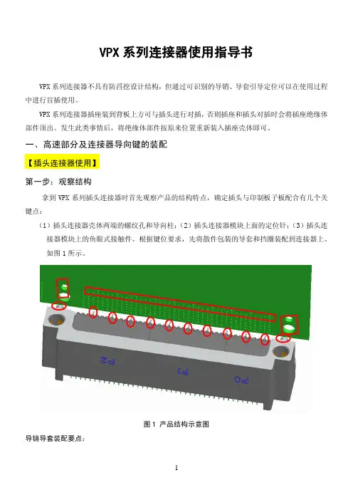
一、高速部分及连接器导向键的装配【插头连接器使用】第一步:观察结构拿到VPX系列插头连接器时首先观察产品的结构特点,确定插头与印制板子板配合有几个关键点:(1)插头连接器壳体两端的螺纹孔和导向柱;(2)插头连接器模块上面的定位针;(3)插头连接器模块上的鱼眼式接触件。
根据键位要求,先将散件包装的导套和挡圈装配到连接器上。
如图1所示。
图1 产品结构示意图导销导套装配要点:3U 连接器有2对导销导套,6U 连接器有3对导销导套,每对导销导套有8个键位,可以防止相同型号的连接器错装,即每个型号的3U 连接器有64种不同的键位组合形式,每个型号的6U 连接器有512种不同的键位组合形式,用以防止错装。
每对导销导套有8个键位,使用时需要导销、导套的键位一致,才能保证连接器的正常对插。
所以导销导套的安装对连接器的正常插合有很大的影响,下面就介绍下导套的安装方法及注意事项,导销安装在插座安装说明中介绍。
1.导套的安装导套安装在插头连接器上,利用弹性挡圈进行固定,如图所示安装步骤:1)首先确定连接器的键位;2)键位确定后,将导套装入插头连接器的导套孔内,安装到位。
注意导套的八方结构与壳体的八方结构相适配;如下图所示:3)导套安装到位后,将弹性挡圈装入壳体的环形挡圈槽中,装入时注意弹性挡圈的开口与壳体的开槽开口方向一致。
装配步骤如下:a)将弹性挡圈的一端放入壳体中,开口与壳体槽口一致; b)稍用力将弹性挡圈大部分装入壳体; c)借用工具将弹性挡圈压进壳体环形槽中;d)弹性挡圈压入后,由于变形,可能会出现两端交错现象,这时调整下弹性挡圈位置即可(利用细小的镊子尖端或者其他可以插入弹性挡圈两端孔内的小工具稍微转动下挡圈即可)至此,导套装配完毕,若要更换导套的键位,利用工具将弹性挡圈取出,更换键位后按照以上安装步骤使用备用的弹性挡圈安装即可,取出的弹性挡圈不再使用。

简述快插式气动管接头的安装与拔出方法-概述说明以及解释1.引言1.1 概述快插式气动管接头是一种常用的连接管道的装置,它能够快速、简便地连接和断开管道,节省了安装和拆卸的时间和劳力。
该接头具有可靠的密封性能和耐压能力,广泛应用于各种气动系统中。
本文主要介绍了快插式气动管接头的安装和拔出方法。
在安装方面,需要做好准备工作,包括检查管道的光洁度和平整度,确保接头的顺利安装。
然后按照一定的步骤进行安装,确保每个连接都紧密牢固,不漏气,不松动。
而在拔出方面,也需要做好准备工作,例如关闭气源,排空管道内的气体等。
然后按照规定的步骤进行拔出,避免对管道和接头造成损坏。
通过本文的介绍,读者可以了解到快插式气动管接头的基本原理和其安装、拔出的方法,对使用和操作这种接头具有一定的指导意义。
另外,本文还对快插式气动管接头的应用前景进行了展望,指出了其在未来气动系统中的重要作用和广阔的发展空间。
总之,快插式气动管接头的安装和拔出方法的研究对于提高气动系统的效率和可靠性具有重要意义。
文章结构部分的内容可以写成如下形式:1.2 文章结构本文主要包括三个部分:引言、正文和结论。
引言部分首先概述了快插式气动管接头的安装与拔出方法,说明了本文的目的是为了介绍这种管接头的安装与拔出过程。
接着描述了文章的结构,即引言、正文和结论。
正文部分是本文的核心内容,主要包括两个方面:快插式气动管接头的基本原理和安装与拔出方法。
首先,通过介绍快插式气动管接头的基本原理,读者可以了解其工作原理和特点。
然后,详细介绍了安装与拔出方法,包括准备工作和具体的步骤。
通过这部分内容,读者可以掌握正确、安全地使用快插式气动管接头的技巧和方法。
结论部分对全文进行总结,并展望了快插式气动管接头的应用前景。
总结部分回顾了快插式气动管接头的基本原理和安装与拔出方法,并强调了其重要性和实用性。
应用前景部分展示了快插式气动管接头在工业生产中的潜在应用领域,为读者提供了进一步了解和研究的方向。
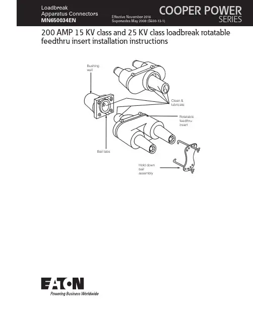
200 AMP 15 KV class and 25 KV class loadbreak rotatable feedthru insert installation instructionsClean &lubricateBushing wellBail tabsHold down bailassemblyRotatable feedthru insertDISCLAIMER OF WARRANTIES AND LIMITATION OF LIABILITYThe information, recommendations, descriptions and safety notations in this document are based on Eaton Corporation’s (“Eaton”) experience and judgment and may not cover all contingencies. If further information is required, an Eaton sales office should be consulted. Sale of the product shown in this literature is subject to the terms and conditions outlined in appropriate Eaton selling policies or other contractual agreement between Eaton and the purchaser.THERE ARE NO UNDERSTANDINGS, AGREEMENTS, WARRANTIES, EXPRESSED OR IMPLIED, INCLUDING WARRANTIES OF FITNESS FOR A PARTICULAR PURPOSE OR MERCHANTABILITY, OTHER THAN THOSE SPECIFICALL Y SET OUT IN ANY EXISTING CONTRACT BETWEEN THE PARTIES. ANY SUCH CONTRACT STATES THE ENTIRE OBLIGATION OF EATON. THE CONTENTS OF THIS DOCUMENT SHALL NOT BECOME PART OF OR MODIFY ANY CONTRACT BETWEEN THE PARTIES. In no event will Eaton be responsible to the purchaser or user in contract, in tort (including negligence), strict liability or other-wise for any special, indirect, incidental or consequential damage or loss whatsoever, including but not limited to damage or loss of use of equipment, plant or power system, cost of capital, loss of power, additional expenses in the use of existing power facilities, or claims against the purchaser or user by its customers resulting from the use of the information, recommendations and descriptions contained herein. The information contained in this manual is subject to changewithout notice.iINSTALLATION INSTRUCTIONS MN650034EN November 2016ContentsDISCLAIMER OF WARRANTIES AND LIMITATION OF LIABILITY . . . . . . . . . . . . . . . . . . . . . . . . . . . . . . . . . . . .I SAFETY FOR LIFE . . . . . . . . . . . . . . . . . . . . . . . . . . . . . . . . . . . . . . . . . . . . . . . . . . . . . . . . . . . . . . . . . . . . . . . . .III SAFETY INFORMATION . . . . . . . . . . . . . . . . . . . . . . . . . . . . . . . . . . . . . . . . . . . . . . . . . . . . . . . . . . . . . . . . . . . .III Safety instructions (iii)PRODUCT INFORMATION . . . . . . . . . . . . . . . . . . . . . . . . . . . . . . . . . . . . . . . . . . . . . . . . . . . . . . . . . . . . . . . . . . .1 Introduction (1)Additional information (1)Acceptance and initial inspection (1)Handling and storage (1)Standards (1)INSTALLATION INSTRUCTIONS . . . . . . . . . . . . . . . . . . . . . . . . . . . . . . . . . . . . . . . . . . . . . . . . . . . . . . . . . . . . . .1 Step 1 (1)Step 2 (2)Step 3 (2)Step 4 (2)REMOVAL INSTRUCTIONS . . . . . . . . . . . . . . . . . . . . . . . . . . . . . . . . . . . . . . . . . . . . . . . . . . . . . . . . . . . . . . . . . .2 ii INSTALLATION INSTRUCTIONS MN650034EN November 2016iiiINSTALLATION INSTRUCTIONS MN650034EN November 2016Eaton’s Cooper Power series products meet or exceed all applicable industry standards relating to product safety. We actively promote safe practices in the use and maintenance of our products through our service literature, instructional training programs, and the continuous efforts of all Eaton employees involved in product design, manufacture, marketing and service.We strongly urge that you always follow all locally approved safety procedures and safety instructions when working around high-voltage lines and equipment and support our “Safety For Life” mission.200 AMP 15 KV class and 25 KV class loadbreak rotatable feedthru insert installation instructionsProduct informationIntroductionEaton’s Cooper Power series Rotatable Feedthru Insertis used to provide dual bushings from a single apparatusbushing well. It makes converting radial-feed transformers tofeed-thru transformers and adding in-line arrester protectionboth easy and practical. Its patented, built-in torque-limiting ratchet prevents operators from accidentally breaking bushing well studs during installation. The ratchet feature also allows the operator to rotate the feedthru insert 360° to orient it in the best position for the application. The bail assembly supplied with the kit can be used to prevent the insert from moving.Eaton’s Cooper Power series 200 A Loadbreak Rotatable Feedthru Insert is designed to be operatedin accordance with normal safe operating procedures . These instructions are not intended to supersede or replace existing safety and operating procedures . The bushing insert should be installed and serviced only by personnel knowledgeable of good safety practices and fully trained on the installation and application of high voltage electrical equipment .All associated apparatus must be de-energized during installation, maintenance or removal .Read and understand the contents of this manualand follow all locally approved procedures and safety practices before installing or operating this equipment .Additional informationThese instructions cannot cover all details or variationsin the equipment, procedures, or process described nor provide directions for meeting every possible contingency during installation, operation, or maintenance. For additional information, contact your Eaton Representative.Acceptance and initial inspectionEach Rotatable Feedthru Insert is in good condition when accepted by the carrier for shipment. Upon receipt, inspect the shipping container for signs of damage. Unpack the Rotatable Feedthru Insert and inspect it thoroughly for damage incurred during shipment. If damage is discovered, file a claim with the carrier immediately.Clean &lubricate BushingwellBail tabsHold downbailassemblyRotatablefeedthruinsertFigure 1 . Rotatable feedthru insert installation into bushing wellHandling and storageBe careful during handling and storage of the Rotatable Feedthru Insert to minimize the possibility of damage. If the Rotatable Feedthru Insert is to be stored for any length of time prior to installation, provide a clean, dry storage area.StandardsISO 9001:2000 Certified Quality Management System Installation instructionsStep 1Clean and lubricate●●Visually inspect for damage and correct rating.●●Verify that apparatus is de-energized.●●Clean any foreign contaminants from the surfaces of the bushing well and rotatable feedthru insert interfaces.●●Apply a thin even coating of grease to mating surfaces of the rotatable feedthru insert and the bushing well. (Refer to Figure 1.)1INSTALLATION INSTRUCTIONS MN650034EN November 2016200 AMP 15 KV class and 25 KV class loadbreak rotatable feedthru insert installation instructionsStep 2Install●●Place base of rotatable feedthru insert into bushing well.●●Turn rotatable feedthru insert clockwise onto bushing well stud.●●An audible click signals that threads and interface are fully seated.●●Continue clockwise rotation to position feedthru.●●Insert the holddown bail hooks into bail tabs and assemble bail across the center of the feedthru insert using wing nuts.Step 3Ground●●Attach copper drain wire (Minimum #14 AWG) to bushing insert drain wire tab.●●Connect drain wire to system ground.Step 4Remove caps●●Remove red shipping caps prior to energizing.Do not energize unit while red shipping caps are on rotatable feedthru insert . Loadbreak Elbows, Surge Arresters, or insulated protective caps should be installed before rotatable feedthru insert is energized .●●Install mating products following instructions supplied with the product.Removal instructions●●De-energize apparatus and verify apparatus isde-energized.●●Remove mating products and place in stand-off device ora clean, dry location.●●Loosen wing nuts of holddown bail and remove bail assembly.●●Remove drain wire.●●Grab bushing interfaces of rotatable feedthru insert and turn counterclockwise until feedthru comes loose from bushing well.2INSTALLATION INSTRUCTIONS MN650034EN November 2016200 AMP 15 KV class and 25 KV class loadbreak rotatable feedthru insert installation instructionsThis page is intentionally left blank.3INSTALLATION INSTRUCTIONS MN650034EN November 2016Eaton1000 Eaton Boulevard Cleveland, OH 44122United StatesEaton’s Power Systems Division 2300 Badger Drive Waukesha, WI 53188United States/cooperpowerseries© 2016 EatonAll Rights ReservedPrinted in USAPublication No. MN650034EN Rev 0 (Supersedes S500131 Rev. 0) November 2016 Eaton is a registered trademark.All trademarks are propertyof their respective owners.For Eaton's Cooper Power series productinformationcall 1-877-277-4636 or visit:/cooperpowerseries.。
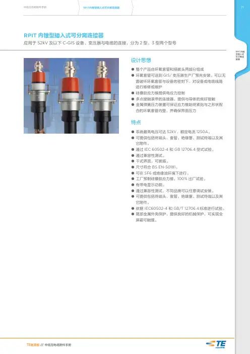
10KV电缆插拔头欧式前接头应用通过630A预制式电缆前接头,可实现单相或三相电缆与开关柜、变压器、电缆分接箱等其他电气设备的连接。
适用于户内或户外安装。
系统工作电压:15kV。
持续额定电流:630A 。
实现多路安装或提供过电压保护。
10KV电缆插拔头电缆特性:10KV电缆插拔头挤包绝缘电力电缆(XLPE,EPR等)10KV电缆插拔头电缆导体截面:25~500mm 210KV电缆插拔头电缆导体类型:铜芯或铝芯10KV电缆插拔头欧式前接头特性10KV电缆插拔头与适合的套管配合时,可提供全屏蔽和全密封可分离连接可长期在水下或其它恶劣环境下使用无最小相间距离要求可以水平、垂直或任意角度安装可带电触摸,对人畜安全可选配带电容测试点一、欧式前接头特点采用预制热(冷)缩技术;进口橡胶,高抗撕阻燃配方,防洪可触摸,可在水中安全运行。
二、用途本终端为屏蔽型螺栓式连接;它适用于环网开关柜、电缆分接箱、箱式变电站的(交联电力电缆)进出线终端,与双通绝缘套管用螺纹联接。
额定电压12KV,额定电流630A,适用电缆截面25-500mm2。
相对配套应力锥与电缆截面配制关系如下:(应力锥端面有相应标示,请安装使用前核对)应力锥内径MM 12 15 18.5 21.5 25.5 29电缆截面(平方MM) 25~50 70~95 120~150 185~240 300 400~500三、结构1.欧式前接头本产品采用美国进口橡胶制作,无毒,无味;下部的应力锥均匀了电缆终端的外屏蔽切断处的电场;2.上部的屏蔽型前接头使带电部分全部密封绝缘,外表面有半导电屏蔽层,工作时外表面接地,可在水中安全运行。
四、欧式前接头安装:安装前先确认应力锥,压接端子和电缆截面相符1、电缆分相处理(见图1)1. 1 按图1 尺寸剥去电缆外护套,长度为800-1200mm;按图示尺寸距外护套端部20mm 钢铠处绑扎几圈铜扎线,并锉亮此段钢铠,沿扎线除去其余的钢铠,同时,除去距钢铠端部10mm 以外的内护套,勿伤及铜屏蔽层。
CAN分离插头从2005年款起适用说明:信息,关于♦继电器位置分配和保险丝位置分配♦多脚插头连接♦控制单元和继电器♦接地连接⇒ 安装位置在一览图中!信息,关于♦故障查询程序⇒ 引导型故障查询******************123456789101112131446a/8HJ 104J 248J 623J 361J 217J 217ws =白色sw =黑色ro =红色br =棕色gn =绿色bl =蓝色gr =灰色li =淡紫色ge =黄色or =桔黄色T16c -16芯黑色插头连接,在自动变速箱控制单元上T17a -17芯红色插头连接,排水槽电控箱左侧接线板T17c -17芯白色插头连接,排水槽电控箱左侧接线板T17d -17芯黑色插头连接,左侧A 柱接线板T20e -20芯黑色插头连接,在自动变速箱控制单元上T46a-46芯插头连接,左CAN 分离插头✱-自动变速箱01J ✱✱-自动变速箱09L✱✱✱- 3.2l 发动机,发动机标识字母AUK #- 4.2l 发动机,发动机标识字母BAT 3.0l 发动机,发动机标识字母BBJ ##- 2.4l 发动机,发动机标识字母BDW###- 3.0l 柴油发动机,发动机标识字母BMK 、BNG******************46a/8LJ 104J 248J 623J 361J 217J 217ws =白色sw =黑色ro =红色br =棕色gn =绿色bl =蓝色gr =灰色li =淡紫色ge =黄色or =桔黄色T16c -16芯黑色插头连接,在自动变速箱控制单元上T17a -17芯红色插头连接,排水槽电控箱左侧接线板T17c -17芯白色插头连接,排水槽电控箱左侧接线板T17d -17芯黑色插头连接,左侧A 柱接线板T20e -20芯黑色插头连接,在自动变速箱控制单元上T46a-46芯插头连接,左CAN 分离插头✱-自动变速箱01J ✱✱-自动变速箱09L✱✱✱- 3.2l 发动机,发动机标识字母AUK #- 4.2l 发动机,发动机标识字母BAT 3.0l 发动机,发动机标识字母BBJ ##- 2.4l 发动机,发动机标识字母BDW###- 3.0l 柴油发动机,发动机标识字母BMK 、BNG******************46a/23H364388386ws=白色sw=黑色ro=红色br=棕色gn=绿色bl=蓝色gr=灰色li=淡紫色ge=黄色or=桔黄色J527-转向柱电子装置控制单元T8a-8芯黑色插头连接,在辅助加热装置控制单元上T10i-10芯红色插头连接,左侧座椅横梁T17v-10芯白色插头连接,排水槽电控箱左侧接线板T16b-16芯插头连接,在组合开关饰板后面T20a-20芯黑色插头连接,左侧A柱T20c-20芯黑色插头连接,左侧B柱T46a-46芯插头连接,左CAN分离插头✱-仅用于美国电子通信系统******************46a/23L364388386ws=白色sw=黑色ro=红色br=棕色gn=绿色bl=蓝色gr=灰色li=淡紫色ge=黄色or=桔黄色J527-转向柱电子装置控制单元T8a-8芯黑色插头连接,在辅助加热装置控制单元上T10i-10芯红色插头连接,左侧座椅横梁T17v-10芯白色插头连接,排水槽电控箱左侧接线板T16b-16芯插头连接,在组合开关饰板后面T20a-20芯黑色插头连接,左侧A柱T20c-20芯黑色插头连接,左侧B柱T46a-46芯插头连接,左CAN分离插头✱-仅用于美国电子通信系统******************J 431J 234J 540J 197J 533J 431J 234J 540J 197J 53346b/8Lws =白色sw =黑色ro =红色br =棕色gn =绿色bl =蓝色gr =灰色li =淡紫色ge =黄色or =桔黄色******************717273747576777879808182838446b/23H644393345446ws =白色sw =黑色ro =红色br =棕色gn =绿色bl =蓝色gr =灰色li =淡紫色ge =黄色or =桔黄色J518-进入及起动许可控制单元J520-车载电网控制单元2J521-带记忆功能的副驾驶员座椅调整控制单元J533-数据总线诊断接口J644-电源管理系统控制单元T10k -10芯红色插头连接,右侧座椅横梁T20b -20芯黑色插头连接,右侧A 柱T20d -20芯黑色插头连接,右侧B 柱T46b-46芯插头连接,右CAN 分离插头B397-主导线束中的连接1(舒适/便捷功能CAN 总线,高速)✱-出租车、警车******************858687888990919293949596979846b/23L644393345446ws =白色sw =黑色ro =红色br =棕色gn =绿色bl =蓝色gr =灰色li =淡紫色ge =黄色or =桔黄色J518-进入及起动许可控制单元J520-车载电网控制单元2J521-带记忆功能的副驾驶员座椅调整控制单元J533-数据总线诊断接口J644-电源管理系统控制单元T10k -10芯红色插头连接,右侧座椅横梁T20b -20芯黑色插头连接,右侧A 柱T20d -20芯黑色插头连接,右侧B 柱T46b-46芯插头连接,右CAN 分离插头B406-主导线束中的连接1(舒适/便捷功能CAN 总线,低速)✱-出租车、警车******************。
Instruction 3015-5415These instructions describe how to install Bacharach’s 2-way and 3-way splitter kits. The splitter kits allow Bacharach’s Single-Zone and Multi-Zone monitors to take gas sample readings from several sample points while utilizing just one zone.It is assumed the user is familiar with the operation and menu system of the monitor in use. If necessary, refer to the unit’s main instruction manual for more detailed operation and maintenance information.ITEMS REQUIRED:•Bacharach Single-Zone or Multi-Zone Refrigerant Monitor •2-way (P/N 3015-5404) or 3-way (P/N 3015-5405) splitter kit • 1/4” outside diameter (0.040” wall) fl ex tubing (3015-3235) or equivalentIMPORTANT APPLICATION NOTES:•The splitter kits are designed for use ONLY in con fi ned/de fi ned spaces with high potential for leaks, such as food cases, cold rooms, refrigeration rack rooms, etc.• Sample intake lines coming off the 2 or 3-way splitter MUST BE OF EQUAL LENGTHAND MUST NOT EXCEED 100 FEET EACH . Failure to do so could result in inaccurate readings.IMPORTANT: When using the splitter kits, the PPM reading for thezone with the splitter kit installed is the average value for the numberof intakes on the splitter. For a 2-way splitter, the PPM reading is theaverage concentration seen between the two pickup points. For a 3-waysplitter, the PPM reading is the average value measured between allthree pickup points. As a result of these readings being averages, Bacha-rach recommends that the alarm set points be lowered appropriately toaccurately notify of a leak•When using a 2-way splitter, the alarms should be 50% of the default values.• For a 3-way splitter they should be lowered to 33% of the defaults.• For accurate fl ow timing the zone distance entry must be the com-bined length of each section of tubing (ex. A 100 foot run to a 3-waysplitter with 20 foot sections off the splitter must be entered as 160feet).WARNING: Splitter kits are not to be used for the monitoring ofammonia.PROCEDURE:Individual sample lines are run from the Multi-Zone unit to each area of the facility to be monitored. Addi-tionally, a purge should be installed to provide clean air for resetting the infrared zero baseline. All air connections are located on the left side of the unit.1. Cut the tubing to the desired length cleanly with a sharp knife. Care should be taken notto distort the tubing ends.World Headquarters 621 Hunt Valley Circle, New Kensington PA 15068-7074PHONE: 724-334-5000 FAX: 724-334-5001 WEBSITE: E-MAIL:********************NOTE: Sample intake lines can be up to 1,200 feet when no exhausttubing is used. Otherwise, the combined length of the sample line andthe exhaust line cannot exceed 1,200 feet. Each section off the splittermust also be included in the total length. For example a 500 foot run to a3-way splitter with 50 foot lengths off the splitter is considered 650 feet ofsample line.2.Connect the initial intake line to the monitor by pushing the tubing fi rmly into the desired connector on the instrument.3.Connect the splitter to the end of the initial intake line by pushing the connector fi rmly onto the tubing.4.Connect the secondary intake lines to the open connections on the splitter. DO NOT leave any of the splitter connections empty.5. Position the secondary intake lines with line end fi lters attached (P/N 3015-3420, includ-ed in splitter kit) near the area to be monitored.See Figure 1 for an example of a typical splitter kit application.For more detailed instructions on the placement of intake lines and applications of Bacharach’s Multi-Zone monitors, refer to the main instruction manual for the speci fi c unit.IMPORTANT: When using the splitter kits, each length of tubingmust be of equal length to ensure accurate readings.。
PowerLok TM10.0 单芯弯头插头组装规范PowerLok TM10.0 1POS 90D Plug Assembly Manual⑤橡胶密封圈Rubber Seal①端子Terminal④金属环Metal Gaskets⑥金属外壳Back Shell③金属套Metal Sleeve步骤2:选取合适线缆(参考手册最后的附录),按照表1尺寸剥离绝缘皮和外皮Step2:Select the right cable(refer to the appendix), prepare the cable according to the sketch and Table 1 below步骤3:拆开连接器,将零件按下图套在剥好的电线上Step3:Load the components in order as the picture shown belowPL28Y -301-70安装步骤Assembly Instruction表1 :剥皮尺寸Table 1:Strip length步骤1:取出连接器, 如图示拆开零件Step1:Take out the connector and take it apart as the picture shown below产品类型Product Type插头类型Plug Type键位&颜色Key & Color系列Series线材尺寸Cable SizePLPowerLok TM28插头连接器,弯头,屏蔽Plug, right angle ,shieldingX 1芯,X 键位橙色1POS , Key ”X” Orange 300300系列300Series3535mm²Y1芯,Y 键位黑色1POS , Key ”Y” Black U 1芯,U 键位黄色1POS , Key ”U”Yellow 5050mm²V 1芯,V 键位绿色1POS , Key ”V” Green 301带高压互锁的300系列300 Series With HVILW 1芯,W 键位红色1POS , Key ”W” Red 7070mm²T1芯,T 键位蓝色1POS , Key ”T”Blue线材尺寸Cable Size A (mm) B (mm)35mm²18±127 ±150mm²18±127 ±170mm²18±127 ±1①端子Terminal ×1②绝缘套Insulation Sleeve ×2③金属套Metal Sleeve ×1④金属环Metal Gaskets ×2⑤橡胶密封圈Rubber Seal ×1⑥金属外壳Back Shell ×1①②③⑤④⑥④横截面Cross Section⑴建议使用附录中的线材,如果要使用客户定制的线材,请联系当地销售,让他们提供延伸的产品Cables written in the appendix are highly recommended for crimping, please contact our local sales for help if you want to use other cables out of this table⑵客户需要重新确认压接区域横截面和拉力测试,这两项达到压接的质量标准A good crimping process is determined by 3 factors: W 、H and tensile test result, please confirm these 3 targets specified are met after crimping⑶横截面仅供参考(其他举例:等边六变形的横截形状),客户负责采购压接工具或刀模Cross section shape is only for reference( other possibilities: hexagonal section), all crimping tools needed are supposed to be prepared by customers步骤5:屏蔽处理5-1自右向左推动金属套盖住绝缘套5-2 外翻屏蔽线,将其覆盖到金属套上,剪切屏蔽线, 保留长度约20mm 5-3剪切尺寸约120mm*25mm 的铜箔,包裹住屏蔽线,确保尾端被包紧5-1③金属套Metal Sleeve 5-220mm (ref)5-3端子压接高宽度尺寸,“W ”:为压接宽度,“H ”为压接高度(相应线径的压接高宽度尺寸及拉力标准参考手册后的附录)Terminal crimping quality depends on 2 parameters: "W" crimping width and "H" crimping height.( Please refer to the appendix at the end of this manual for details)步骤4:压接端子(规格参照手册最后的附录,附录数据仅供参考) ,然后将绝缘筒安装在电线上Step4:Crimp the terminal(Please refer to the appendix for details at the end of this manual), then buckle the twininsulation sleeves together on the terminal crimped as the picture below备注:根据线材类型变化,选择使用铜箔的用量. 厚屏蔽结构的线不要求包铜箔Note :Amount of copper foil will vary for other cable types.Not required for heavy shielding constructions②绝缘套Insulation sleeve步骤6:组装金属外壳Step6:Assemble the Back shell⑤橡胶密封圈Rubber Seal④金属环Metal Gaskets⑥金属外壳Back Shell6-1套上金属外壳,使其与金属环和密封圈紧密接触6-1Bring the metal gaskets and the rubber seal nearer and keep them in touch with the metal sleeveStep5:Shielding braid preparation5-1make the cable through the copper sleeve, and slide the copper sleeve to cover inner insulation layer5-2flip over the shielding braid and cut it into 20mm‘s length, and put it on the surface of copper sleeve 5-3wrap the shielding braid with a piece of copper foil of 120mm*25mm, make sure the braid is fully covered by the copper foil6-2 锁紧金属外壳完成组装,铁壳锁紧力矩为10~12 N.m6-2Screw up the shell with a torque of 10-12N.m to finish the assembly步骤7:建议客户参考下面的测试参数,对线束进行绝缘电阻测试和耐压测试Step7:Insulation resistance and dielectric withstand voltage tests are obligated to be done according to below test parameters to guarantee the good electric performance of the whole harness 7-1绝缘电阻测试7-1 Insulation Resistance Test位置Positions 测试电压(直流)Test Voltage(DC)绝缘电阻Insulation Resistance电缆芯线到壳体Cable(power) to shell1000 V> 500 MΩ电缆芯线到高压互锁Cable(power) to HVIL1000V> 500 MΩ高压互锁到壳体HVIL to shell1000 V> 100 MΩ7-2耐压测试7-2Dielectric Withstand Voltage Test位置Positions 测试电压(直流)Test Voltage(DC)漏电流Leakage Current电缆芯线到壳体Cable(power) to shell5000 V<5mA电缆芯线到高压互锁Cable(power) to HVIL5000 V<5mAHVIL to shell高压互锁到壳体500V<5mA⑤橡胶密封圈Rubber Seal①端子Terminal③塑胶套Plastic Sleeve ④金属环Metal Gaskets⑥金属外壳Back Shell步骤2:选取合适线缆(参考手册最后的附录),按照表2尺寸剥离绝缘皮和外皮Step2:Select the right cable(refer to the appendix), prepare the cable according to the sketch and Table 2 below步骤3:拆开连接器,将里面的零件按下图套在剥好线皮的电线上Step3:Load the components in order as the picture shown belowPL58Y -301-70A步骤1:取出连接器, 如图示拆开零件Step1:Take out the connector and take it apart as the picture shown below产品类型Product Type插头类型Plug Type键位&颜色Key & Color系列Series线材尺寸Cable SizePLPowerLok TM58插头连接器,弯头,非屏蔽Plug, right angle , unshieldingX 1芯,X 键位橙色1POS , Key ”X” Orange 300300系列300Series3535mm²Y 1芯,Y 键位黑色1POS , Key ”Y” Black U1芯,U 键位黄色1POS , Key ”U”Yellow 5050mm²V 1芯,V 键位绿色1POS , Key ”V” Green 301带高压互锁的300系列300 Series With HVILW 1芯,W 键位红色1POS , Key ”W” Red 7070mm²T1芯,T 键位蓝色1POS , Key ”T”Blue表2:剥皮尺寸Table 2:Strip length线材尺寸Cable Size A (mm)35mm²18±150mm²18±170mm²18±1①端子Terminal ×1②绝缘套Insulation sleeve ×2③塑料套Plastic Sleeve ×1④金属环Metal Gaskets ×2⑤橡胶密封圈Rubber Seal ×1⑥金属外壳Back Shell ×1①②③⑤④⑥④安装步骤Assembly Instruction横截面Cross section步骤5:组装金属Step5:Assemble the Back shell5-2将塑胶套及金属环、橡胶密封圈紧密接触5-2 Bring the metal gaskets and the rubber seal nearer and keep them in touch with the plastic sleeve③塑胶套Plastic Sleeve⑤橡胶密封圈Rubber Seal④金属环Metal Gaskets⑥金属外壳Back Shell5-1装上塑胶套5-1 Assemble Plastic sleeve②绝缘套Insulation Sleeve端子压接高宽度尺寸,“W ”:为压接宽度,“H ”为压接高度(相应线径的压接高宽度尺寸及拉力标准参考手册后的附录)Terminal crimping quality depends on 2 parameters: "W" crimping width and "H" crimping height.( please refer to the appendix at the end of this manual for details)5-3锁紧金属外壳完成组装,外壳锁紧力矩为10~12 N.m5-3 Screw up the shell with a torque of 10-12N.m to finish the assembly⑴建议使用附录中的线材,如果要使用客户定制的线材,请联系当地销售,让他们提供延伸的产品Cables written in the appendix are highly recommended for crimping, please contact our local sales for help if you want to use other cables out of this table⑵客户需要重新确认压接区域横截面和拉力测试,这两项达到压接的质量标准A good crimping process is determined by 3 factors: W 、H and tensile test result, please confirm these 3 targets specified are met after crimping⑶横截面仅供参考(其他举例:等边六变形的横截形状),客户负责采购压接工具或刀模Cross section shape is only for reference( other possibilities: hexagonal section), all crimping tools needed are supposed to be prepared by customers步骤4:压接端子(规格参照手册最后的附录,附录数据仅供参考) ,然后将绝缘筒安装在电线上Step4:Crimp the terminal (please refer to the appendix for details at the end of this manual ),then buckle thetwin insulation sleeves together on the terminal crimped as the picture below步骤6:建议客户参考下面的测试参数,对线束进行绝缘电阻测试和耐压测试Step6:Insulation resistance and dielectric withstand voltage tests are obligated to be done according to below test parameters to guarantee the good electric performance of the whole harness 6-1绝缘电阻测试6-1 Insulation Resistance Test位置Positions 测试电压(直流)Test Voltage(DC)绝缘电阻Insulation Resistance电缆芯线到壳体Cable(power) to shell1000 V> 500 MΩ电缆芯线到高压互锁Cable(power) to HVIL1000V> 500 MΩ高压互锁到壳体HVIL to shell1000 V> 100 MΩ6-2耐压测试6-2Dielectric Withstand Voltage Test位置Positions 测试电压(直流)Test Voltage(DC)漏电流Leakage Current电缆芯线到壳体Cable(power) to shell5000 V<5mA电缆芯线到高压互锁Cable(power) to HVIL5000 V<5mAHVIL to shell高压互锁到壳体500V<5mA附录APPENDIX线缆压接的参考规范Reference specification for cable crimping线缆类型Cable Type电线尺寸Cable Size导体结构(mm)Conductor导体外径(mm)Conductor OD电线外径(mm)Wire OD压接高度H(mm)Crimping height压接宽度W(mm)Crimping Width参考保持力RetentionForce屏蔽线Shielding cable 35mm²3071*0.128.1014.50±0.39.5±0.211.0±0.22300N 50mm²4403*0.129.517.00±0.311.5±0.213.3±0.22800N 50mm²385*0.419.414.90±0.313.3±0.212.2±0.22800N 70mm²3876*0.1511.819.50±0.313.0±0.215.0±0.23400N 70mm²360*0.5111.617.00±0.315.0±0.213.26±0.23400N非屏蔽线Un-shieldingcable 35mm²3071*0.128.1011.50±0.39.5±0.211.0±0.22300N 50mm²4403*0.129.513.60±0.311.5±0.213.3±0.22800N 50mm²385*0.419.411.5±0.313.3±0.212.2±0.22800N 70mm²3876*0.1511.815.50±0.313.0±0.215.0±0.23400N 70mm²360*0.5111.613.7±0.315.0±0.213.26±0.23400N线缆压接的参考规范Reference specification for cable crimpingAmphenol Technical Products International provides the above product specifications for the standard PowerLok™series of connectors to assist users in identifying the correct product for the system to which the connectors may be applied.Specifications are subject to change without notice.Contact your nearest Amphenol Corporation Sales Office for the latest specifications.All statements, information and data given herein are believed to be accurate and reliable but are presented without guarantee,warranty,or responsibility of any kind,expressed or implied.Statements of suggestions concerning possible use of our products are made without representation or warranty that any such use is free of patent infringement and are not recommendations to infringe any patent. Specifications are typical and may not apply to all connectors.Note that these specifications are derived from relevant global standards used in the automotive and industrial transportation markets,but they are not a substitute for system level design validation testing,which is the sole responsibility of the system designer and/or end user.Amphenol Technical Products InternationalAsia PacificGuangZhou, ChinaTel: +86 20-3210 6099Add: No.5 JianTa Shan Road, GuangZhou Science cityPostal code: 510663North AmericaWinnipeg, CanadaTel: +1 204 697 2222Add: 2110 Notre Dame AvenueEuropeMilano, ItalyTel: +39 02 932541Add: Via Barbaiana5, 20020 Lainate(MI)Email:*********************。