EB500V2.7.0 版本更新说明
- 格式:pdf
- 大小:206.91 KB
- 文档页数:12
轻松入门 EasyBuilder500----软件使用介绍为了让更多的朋友会使用EasyBuilder软件,现在推出[轻松入门EasyBuilder]连载,循序渐进介绍该软件如何使用,此次先对软件做一个整天概数,其它功能的使用会在以后逐步介绍。
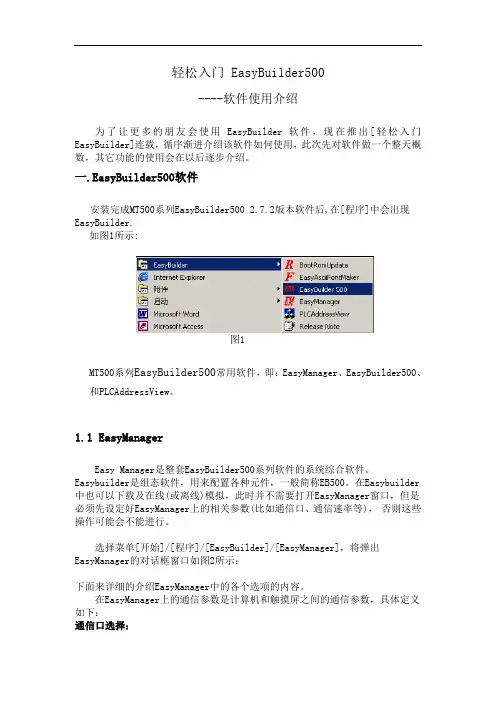
一.EasyBuilder500软件安装完成MT500系列EasyBuilder500 2.7.2版本软件后,在[程序]中会出现EasyBuilder.如图1所示:图1MT500系列EasyBuilder500常用软件,即:EasyManager、EasyBuilder500、和PLCAddressView。
1.1EasyManagerEasy Manager是整套EasyBuilder500系列软件的系统综合软件。
Easybuilder是组态软件,用来配置各种元件,一般简称EB500。
在Easybuilder 中也可以下载及在线(或离线)模拟,此时并不需要打开EasyManager窗口,但是必须先设定好EasyManager上的相关参数(比如通信口、通信速率等),否则这些操作可能会不能进行。
选择菜单[开始]/[程序]/[EasyBuilder]/[EasyManager],将弹出EasyManager的对话框窗口如图2所示:下面来详细的介绍EasyManager中的各个选项的内容。
在EasyManager上的通信参数是计算机和触摸屏之间的通信参数,具体定义如下:通信口选择:选择计算机和触摸屏相连接的计算机的串口为COM1或COM2(可选择COM1~COM10)。
通信口速率选择:在下载/上传时决定计算机和触摸屏之间的数据传输速率,建议选择115200bps(一般对于一些老型机器或特殊要求时才选用38400bps)。
Project Download/Upload or Recipe Download/Upload:上传/下载工程或者上传/下载配方资料数据。
Project:工程的所有相关文件Recipe:配方资料数据Complete or Partial Download/Upload:对于下载,“complete” 是包含工程文件(*.eob)和系统文件(*.bin)一起下载,速度较慢;“Partial”则仅下载工程文件(*.eob),速度较快。
QUICK REFERENCE GUIDEEnglish Version 1.0V C D300 S er i e sRemote Agent 7.0 SoftwareVCD300 Series - Remote Agent 7.0 Quick Reference GuideAdding a Site1. Double-click on the Remote Agent 7.0 icon on the desktop.2. Enter your user name (default: Administrator) and password and click on “OK”.3. In the Site window on the left, right click on “Site” and select “Add”.4. In the “Site Info” box enter the following, and press “OK”. Connection Type: LAN Site Name: enter a name to identify your site (eg: My Business)Server IP: enter the IP address of your DVR/site (eg:192.168.1.150) User ID: admin (default) Password: enter the DVR password (eg: 1234)Channel: camera channels (eg: 1-6)VCD300 Series - Remote Agent 7.0 Quick Reference GuideViewing Live Cameras1. On the left side of the screen, below the Site window, click “Live”2. Under “Site”, highlight the name of your site with your mouse and holding down the left mouse button drag thesite over to the Channel 1 window and release. If the DVR and Remote Agent are configured properly the cameras will display in the viewing windows.VCD300 Series - Remote Agent 7.0 Quick Reference GuidePlaying Back Recorded Video1. On the left side of the screen – click “Playback” and select the date and time you would like to playback.2. Under “Site”, highlight the name of your site with your mouse and holding down the left mouse button drag thesite over to the Channel 1 window and release. The cameras will load in pause mode with a green “V” in the top right corner of each screen.VCD300 Series - Remote Agent 7.0 Quick Reference Guide3. To start playback select the “Play” tab, check “Multicontrol” (to control all the cameras) and press the “Play”button. The cameras will all start playing.Saving Playback Video to PC1. Create a folder on your computer that you would like to save your video to.2. In Remote Agent, click on the “Options” tab on the top. (The screwdriver and the gear)VCD300 Series - Remote Agent 7.0 Quick Reference Guide3. In the “Play” tab under “VOD File Save Folder”, click “Browse”.4. Browse to the folder you created in step1 and press “OK”.5. Press “OK” again to close the “Options” box.VCD300 Series - Remote Agent 7.0 Quick Reference Guide6. On the left side of the screen – click on “Playback” and select the date and time you would like to playback.Check the “File Save” box.7. Under “Site” highlight the name of your site with your mouse and holding down the left mouse button drag thesite over to the Remote Agent Channel 1 window and release. The cameras will start playing and saving the video to the VOD file save folder on your computer. A green “Vs” will appear in the corner of each screen.VCD300 Series - Remote Agent 7.0 Quick Reference GuidePlaying Back “File Save” Video1. In the “Site” window, right click on “File” and select “Add”.2. In the “Site Info” box, click on “Add”.VCD300 Series - Remote Agent 7.0 Quick Reference Guide3. Inthe “Open” box, browse to the folder you saved your video to (ie: your VOD File Save Folder).4. In your VOD File Save Folder there will be a folder with the name of your site (eg: 1_Lab Demo). Highlight thesite name and click on“Open”.5. In the site folder will be a folder for each day that you backed up video.Select the date of the video you wish to playback and click on “Open”.VCD300 Series - Remote Agent 7.0 Quick Reference Guide6. In this folder there will be a file for each camera backed up that day.The file name corresponds to the starting time and the channel for that recording(Format: hour/minutes/seconds/channel. The last two numbers identify the channel; 00=ch1; 01=ch2 ……)7. Select the camera(s) you wish to playback, the click on “Open.”To select all the cameras, highlight the first file, press “Shift” (on your keyboard), highlight the last file, then click “Open”.8. You will be prompted to “Input Selected File Name”. Select a name that will identify the video for you andpress “OK”.VCD300 Series - Remote Agent 7.0 Quick Reference Guide9. Press “OK” to exit the “Site Info”box.10. The playback files will be listed under “File” in the Site window. There will be one file for each camera.VCD300 Series - Remote Agent 7.0 Quick Reference Guide11. To play back the video drag the video file over to the Remote Agent viewing window.To play back multiple files, highlight the first file, press “Shift”(on your keyboard) then highlight the last file and using your left mouse button drag the files over to the Remote Agent viewing window.12. The saved video will play back.PRODUCT SUPPORTIt’s all on the WebFor additional information or troubleshooting help, refer to your owners manual for assitance.WWW.DIGIMERGE.COM WWW.DIGIMERGE.COM。
软件和驱动版本更新工具的使用方法
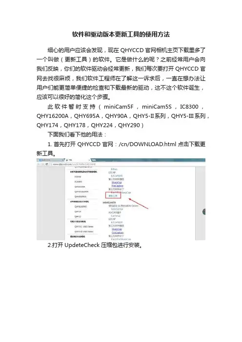
细心的用户应该会发现,现在QHYCCD官网相机主页下载里多了一个叫做(更新工具)的软件。
它是做什么的呢?之前经常用户会向我们反映,你们的软件驱动会经常更新,我们每次要打开QHYCCD官网去找很麻烦,我们软件工程师在了解这一诉求后,一直在想办法让用户们能更简单便捷的检查和下载最新的驱动,这不这个软件诞生,应该可以很好的简化这个步骤。
此软件暂时支持(miniCam5F,miniCam5S,IC8300,QHY16200A,QHY695A,QHY90A,QHY5-II系列,QHY5-III系列,QHY174,QHY178,QHY224,QHY290)
下面我们看下他的用法:
1.首先打开QHYCCD官网:/cn/DOWNLOAD.html点击下载更新工具。
2.打开UpdeteCheck压缩包进行安装。
3.注意要首先要先连接QHYCCD相机,然后打开软件。
4.点击检查更新。
5.看看那些需要更新,点击download
6.直接跳转到相应的下载页面,下载更新相应的软件和驱动就可以了。


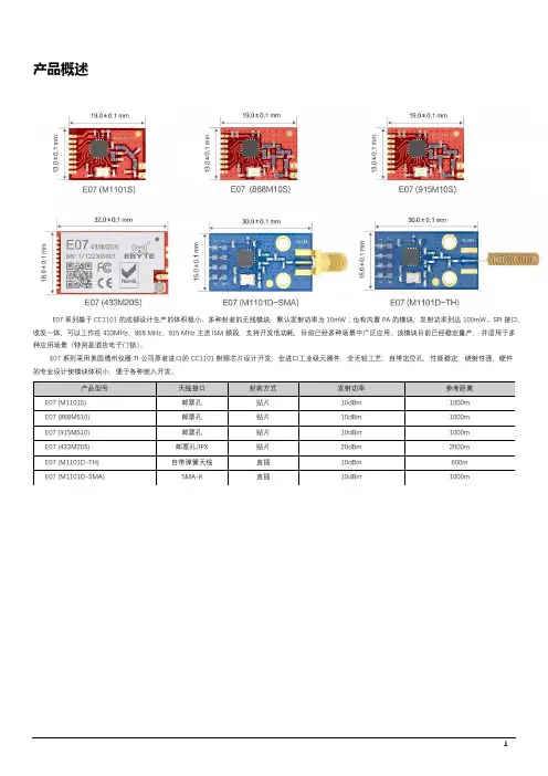
产品概述E07系列基于CC1101的成都设计生产的体积极小、多种封装的无线模块,默认发射功率为10mW;也有内置PA的模块,发射功率到达100mW。
SPI接口,收发一体,可以工作在433MHz、868MHz、915MHz主流ISM频段,支持开发低功耗,目前已经多种场景中广泛应用。
该模块目前已经稳定量产,并适用于多种应用场景(特别是酒店电子门锁)。
E07系列采用美国德州仪器TI公司原装进口的CC1101射频芯片设计开发,全进口工业级元器件,全无铅工艺,自带定位孔,性能稳定,绕射性强,硬件的专业设计使模块体积小,便于各种嵌入开发。
目录产品概述 (1)1.技术参数 (3)1.1.通用参数 (3)1.2.电气参数 (3)1.2.1.发射电流31.2.2.接收电流31.2.3.关断电流31.2.4.供电电压41.2.5.通信电平4 1.3.射频参数 (4)1.3.1.发射功率41.3.2.接收灵敏度 (4)1.3.3.推荐工作频率 (5)1.4.距离测试 (5)2.机械特性 (5)2.1.E07(M1101S)/E07(868MS10)/E07(915MS10) (5)2.2.E07(M1101D-TH)/E07(M1101D-SMA) (6)2.2.E07(433M20S) (7)3.生产指导 (8)3.1.回流焊温度 (8)3.2.回流焊曲线图 (8)4.常见问题 (9)4.1.通信距离很近 (9)4.2.模块易损坏 (9)5.重要声明 (9)6.关于我们 (9)1.技术参数1.1.通用参数产品型号核心IC 尺寸模块净重工作温度工作湿度储存温度E07(M1101S)CC110113*19mm 0.8±0.1g -40~+85°C 10~90-40~+125°C E07(868MS10)CC110113*19mm 0.8±0.1g -40~+85°C 10~90-40~+125°C E07(915MS10)CC110113*19mm 0.8±0.1g -40~+85°C 10~90-40~+125°C E07(433M20S)CC110118*32mm 3.0g±0.1g -40~+85°C 10~90-40~+125°C E07(M1101D-TH)CC110115*28mm 2.4±0.1g -40~+85°C 10~90-40~+125°C E07(M1101D-SMA)CC110115*30mm3.2g±0.1g-40~+85°C10~90-40~+125°C1.2.电气参数1.2.1.发射电流产品型号Min Typ Max 单位备注E07(M1101S)272932mA ●在针对模块设计供电电路时,往往推荐保留30以上余量,有整机利于长期稳定地工作;●发射瞬间需求的电流较大但是往往因为发射时间极短,消耗的总能量可能更小;●当客户使用外置天线时,天线与模块在不同频点上的阻抗匹配程度不同会不同程度地影响发射电流的大小。

Release NotesPowerMonitor 500 Unit Base Firmware, Ethernet Firmware, and SoftwareCatalog Numbers 1420-V1, 1420-V2, 1420-V1A, 1420-V1P, 1420-V2A, 1420-V2P, 1420-V1-ENT, 1420-V1-485, 1420-V2-ENT, 1420-V2-485, 1420-V1A-ENT, 1420-V1A-485, 1420-V2A-ENT, 1420-V2A-485, 1420-V1P-ENT, 1420-V1P-485, 1420-V2P-ENT, 1420-V2P-485System Features This software update includes new features.Software Version 1.0.0.14•Phase Sequence Indication for Systems in Software T oolPhase sequence indication is now shown for all involved systems (3P,3P1, 3Pn). Previously, the phase sequence was shown for only 3Pn.•Reading of kVARh Counters in Software T oolReadings for kVARh counters are now shown when the system is in 3Pconfiguration.PowerMonitor 500 Unit Base Firmware, Ethernet Firmware, and SoftwareBase Firmware Revision 12These system features are first identified as of base firmware revision 12.•The title of the programming menu page 260 was changed from ENDto SAVE to more clearly indicate the function of the page.•The Change Password (CHANGE PAS?) menu page 10 was moved tothe end of the programming menu, just before the SAVE menu page.Due to this change, the menu page numbers for some of the menus havechanged. For example, in units with firmware revision 11 and earlier, theSYSTEM menu page is 50. In units with firmware revision 12 and later,the SYSTEM menu page is 40.Firmware 11 andEarlier2Rockwell Automation Publication 1420-RN001B-EN-P - January 2017PowerMonitor 500 Unit Base Firmware, Ethernet Firmware, and Software Anomalies These firmware revisions include corrected anomalies from the previousrevision.Corrected Anomalies for Base Firmware Revision 11•CORRECTED: Display Indication for 'VLNsys' in 3P SystemSelectionKnown anomaly that was first identified as of firmware revision 9.When the system is selected to be 3P configuration, the displayindication of 'VLNsys' is shown.•CORRECTED: Keypad Management Not Advancing the PageKnown anomaly that was first identified as of firmware revision 9. Pagesoccasionally do not advance when a keypad button is pressed eventhough the T ouch Icon indicates that a button was pressed.•CORRECTED: Moving the Cursor on Password PageKnown anomaly that was first identified as of firmware revision 9.When using the buttons on the front display to enter the password, thecursor does not move past the first digit of the password. The use of thebutton to move the cursor in the password setting field exits theprogram menu and returns the screen to the measuring display. For unitswith optional communication, the software tool can be used to enter thepassword and access the programming mode.Corrected Anomalies for Ethernet Firmware Revision 4.002•CORRECTED: Active Ethernet Connection Required After PowerUpKnown anomaly that was first identified as of firmware revision 4.001.A PowerMonitor 500 unit with Ethernet firmware revision 4.001requires an active Ethernet network connection within 60 seconds ofpower-up, otherwise no connection is established. ThePowerMonitor500 unit has a red 'x' in RSLinx® and cannot be pinged.Power cycling the PowerMonitor 500 unit can recover communicationas long as an active Ethernet network connection is in place within 60seconds.•CORRECTED: TCP/IP Connection Loss with Fast Socket RequestRateKnown anomaly that was first identified as of firmware revision 4.001.When there is a fast closing-opening cycle of the TCP/IP stack socketinterface, an exception can occur and no further connections areallowed. More specifically, when a socket is closed, the TCP/IP stackremoves the relevant data structure present in the queue in a maximumof 1 ms. If a socket is requested to open before that period, then a nullpointer exception is generated and the stack does not accept any otherconnections. Power must be cycled to recover the unit.Rockwell Automation Publication 1420-RN001B-EN-P - January 20173Allen-Bradley, PowerMonitor, Rockwell Automation, Rockwell Software, and RSLinx are trademarks of Rockwell Automation, Inc.Trademarks not belonging to Rockwell Automation are property of their respective companies.Rockwell Otomasyon Ticaret A.Ş., Kar Plaza İş Merkezi E Blok Kat:6 34752 İçerenköy, İstanbul, T el: +90 (216) 5698400Rockwell Automation maintains current product environmental information on its website at /rockwellautomation/about-us/sustainability-ethics/product-environmental-compliance.page .Publication 1420-RN001B-EN-P - January 2017Supersedes Publication 1420-RN001A-EN-P - June 2016Copyright © 2017 Rockwell Automation, Inc. All rights reserved. Printed in the U.S.A.Corrected Anomaly for Software Version 1.0.0.14•CORRECTED : Indication of Neutral Current for 3P2 System in Software T oolKnown anomaly that was first identified as of software version 1.0.0.11. Whensystem is in 3P2 setting, the neutral current indication, An, is shown. This neutralcurrent indicator does not appear in some cases.Download Firmware The latest PowerMonitor 500 unit Ethernet firmware is found at the following website:/Pages/MultiProductDownload.aspx.From the Category pull-down menu, choose Energy Monitoring.Additional ResourcesThese documents contain additional information concerning related products from Rockwell Automation.Y ou can view or download publications at /global/literature-library/overview.page . T o orderpaper copies of technical documentation, contact your local Allen-Bradley distributor orRockwell Automation sales representative.Resource DescriptionCommunication Firmware in PowerMonitor 500 Units with EtherNet/IP Network Communication Installation Instructions, publication 1420-IN001This document provides instructions on how to update your firmware revision.PowerMonitor 500 Unit User Manual, publication 1420-UM001Provides installation instructions, wire diagrams, configuration, and specifications for PowerMonitor 500 units.Industrial Automation Wiring and Grounding Guidelines, publication 1770-4.1Provides general guidelines for installing a Rockwell Automation® industrial system.Product Certifications website, Provides declarations of conformity, certificates, and other certification details.。
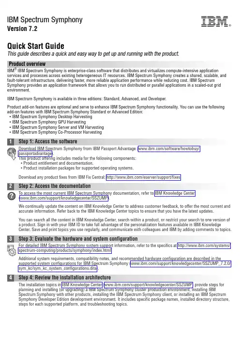
IBM Spectrum SymphonyVersion 7.2Quick Start GuideThis guide describes a quick and easy way to get up and running with the product.Product overviewIBM ®IBM Spectrum Symphony is enterprise-class software that distributes and virtualizes compute-intensive application services and processes across existing heterogeneous IT resources. IBM Spectrum Symphony creates a shared, scalable, and fault-tolerant infrastructure, delivering faster, more reliable application performance while reducing cost. IBM Spectrum Symphony provides an application framework that allows you to run distributed or parallel applications in a scaled-out grid environment.IBM Spectrum Symphony is available in three editions: Standard, Advanced, and Developer.Product add-on features are optional and serve to enhance IBM Spectrum Symphony functionality. You can use the following add-on features with IBM Spectrum Symphony Standard or Advanced Edition:v IBM Spectrum Symphony Desktop Harvestingv IBM Spectrum Symphony GPU Harvestingv IBM Spectrum Symphony Server and VM Harvestingv IBM Spectrum Symphony Co-Processor Harvestingv Product entitlement and documentation.v Product installation packages for supported operating systems.Download any product fixes from IBM Fix Central: /eserver/support/fixes.We continually update the content on IBM Knowledge Center to address customer feedback, to offer the most current and accurate information. Refer back to the IBM Knowledge Center topics to ensure that you have the latest updates.You can search all the content in IBM Knowledge Center, search within a product, or restrict your search to one version of a product. Sign in with your IBM ID to take full advantage of the personalization features available in IBM Knowledge Center. Save and print topics you use regularly, and communicate with colleagues and IBM by adding comments to topics.Additional system requirements, compatibility notes, and recommended hardware configuration are described in the supported system configurations for IBM Spectrum Symphony (/support/knowledgecenter/SSZUMP_7.2.0/sym_kc/sym_kc_system_configurations.dita).Spectrum Symphony with other products, installing the IBM Spectrum Symphony client, or installing an IBM Spectrum Symphony Developer Edition development environment. It includes specific package names, installed directory structure,steps for each supported platform, and troubleshooting topics.IBM®Once you have installed, entitled, and configured IBM Spectrum Symphony, refer to the managing, developing, reference, and troubleshooting topics within IBM Knowledge Center.More informationFor additional information about IBM Spectrum Symphony, refer to the following resources:v IBM Spectrum Symphony technical computing community(https:///storage/products/ibm-spectrum-symphony)v IBM Spectrum Symphony product information (/systems/spectrum-computing/products/symphony/index.htmlv IBM Knowledge Center (/support/knowledgecenter/SSZUMP)v IBM Redbooks®()Access technical support information for all IBM products from the IBM Support Portal (/support).IBM Spectrum Symphony 7.2. Licensed Materials - Property of IBM. U.S. Government Users Restricted Rights - Use, duplication or disclosure restricted by GSA ADP Schedule Contract with IBM Corp.IBM, the IBM logo, and ®are trademarks or registered trademarks of International Business Machines Corp., registered in many jurisdictions worldwide. Other product and service names might be trademarks of IBM or other companies. A current list of IBM trademarks is available on the Web at “Copyright and trademark information” (/legal/copytrade.shtml).Part Number:CNI6MENPrinted in Ireland。
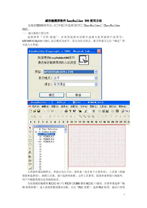
威伦触摸屏软件EasyBuilder 500使用方法安装好EB500软件后,在[开始]中选择[程序]/[EasyBuilder]/[EasyBuilder 500]。
一、建立新的工程文件选择菜单“文件\新建”,在类型选择对话框中选择人机界面的产品型号:MT506T/C/M(320×234),显示模式为水平,语言为东方语言。
新文件建立之后“确定”即可进入主界面。
主界面外观如图所示,界面分为几个区:菜单条(包含9个主菜单项)、工具条(快捷按钮和选择项)、画图工具条、窗口选择列表框、元件工具条等。
除菜单条和窗口画面外,用户可根据需要决定其他的取舍。
为实现威伦触摸屏RS232端口与FX2N-232BD模块RS232口通讯,在菜单条选择“编辑/系统参数”,进入系统参数设置对话框,点击“PLC设置”,选择PLC机型、通讯口类型及通讯参数,如下图所示。
完成后“确定”。
PLC端设置:新建工程后,点击左边工程数据列表中的参数选项—PLC参数(双击进入),点击PLC系统(2)菜单按下图设置。
设置完成后就可正常的编写PLC程序,在进行程序下载(写入PLC)时,选择PLC参数选项将刚设置好的参数一并下载。
以后改变PLC程序后下载时就不再选择PLC参数选项。
二、窗口画面设定窗口是EB500的工程的基本元素。
每个屏幕都是由一些窗口组成。
窗口有3种类型:基本窗口,公用窗口和快选窗口。
改变大小以后的基本窗口还可以当作弹出窗口使用。
所有的窗口都可以作为底层窗口。
基本窗口是通常窗口的类型。
当用”切换基本窗口”命令来切换基本窗口时,当前屏幕会清屏(除了公用窗口和快选窗口之外的窗口都会被清掉),而要切换的基本窗口会显示在当前屏幕上。
当基本窗口上的元件调用弹出窗口时,基本窗口的原始信息会保留,而调用的弹出窗口会附加到当前基本窗口上,所有的这样的弹出窗口与基本窗口都是父子窗口的关系。
当从基本窗口N切换到基本窗口M时,所有窗口N 的子窗口都将关闭,而显示窗口M和窗口M的子窗口。
Release Notes PowerFlex 700 Drive w/Vector Control Option (Revision 40.001)These release notes correspond to the firmware version 40.001 for PowerFlex® 700 drives using the new Variable Boost V oltage function. This version of firmware incorporates all functions included in PowerFlex 700 drive firmware version 6.001.Determining Firmware Revision Level To determine the firmware version for a PowerFlex 700 Drive, view parameter 29 [Control SW Ver].Firmware Upgrade Procedure This section describes procedures to flash upgrade your drive firmware. Downloads are provided on the Allen-Bradley Web Updates site located at /support/abdrives/webupdate. For a detailed explanation of the flash procedure, refer to /support/abdrives/ powerflex700vc/phase1/firmware/index.html.Important:Once a flash update has been started, do not remove drive power until the download is complete and the drive has beenreset. If power is removed during Boot Flash, the drive may bepermanently damaged. A drive that has been damaged in thisway cannot be repaired. If power is removed duringApplication Flash, the drive will remain in Boot and can bereflashed.1.Remove/disconnect any HIMs before proceeding.2.Install the “v40.001 Flash Kit” from the Allen-Bradley Web Updates site.This automatically installs the latest version of the ControlFLASH utility on your computer. ControlFLASH, DriveExplorer or DriveExecutive can now be used to update the drive using the following instructions.Using ControlFLASHImportant:This method requires RSLinx.unch ControlFLASH (if it is not already running).2.Follow the screen prompts until the flash procedure is completed and thenew firmware version is displayed.ATTENTION: Risk of drive damage exists if drive power isremoved during the Boot Flash segment of the upgrade/download.To guard against damage, Do Not Remove Power to the driveuntil the download is complete and the drive has been reset.2PowerFlex 700 Drive w/Vector Control Option (Revision 40.001)Using DriveExplorer Lite/Full1.Exit the ControlFLASH program (if it is running) and launchDriveExplorer. Make a connection to the drive.2.In the DriveExplorer treeview, select the appropriate drive. Then selectthe Information icon.3.On the Properties screen, select the “Details” tab.4.Select “Flash Update” and follow the screen prompts until the procedureis completed and the new firmware version is displayed.Using DriveExecutiveImportant:This method requires RSLinx.1.Exit the ControlFLASH program (if it is running) and launchDriveExecutive. Make a connection to the drive.2.In the DriveExecutive treeview, select the appropriate drive. Then selectthe Information icon.3.On the Properties screen, select “Component Details.”4.Select “Flash Update” and follow the screen prompts until the procedureis completed and the new firmware version is displayed. Enhancements This section describes the enhancements included in this revision:Variable Boost Voltage FunctionThe Variable Boost V oltage function provides a reliable means of selectingthe appropriate fixed-value boost voltage in V/Hz mode to allow a drive(s)to start a load with a high variable level of breakaway torque and to allow adrive(s) to start into a rotating load in order to provide a controlleddeceleration when shutting down.Configuration and OperationTo enable the variable boost voltage function:1.Set [Motor Cntl Sel], parameter 53 to 2 “Custom V/Hz”2.Set bit 0 “VB Enable” of parameter 575 [Boost Config] to “1”Bit 0 “VB Enabled” of parameter 576 [Boost Status] is set to “1” when theabove two conditions are met.Immediately following a valid drive run command, the drive produces themotor voltage specified in [Start Boost], parameter 69 at the frequencyspecified in [Boost Frequency], parameter 566. The actual motor boostvoltage can be viewed in [Boost V oltage], parameter 560. Parameter 23[Speed Reference], regardless of the speed reference source, and parameter2 [Commanded Speed], regardless of the linear ramp and S-curve settings,are held at the value of [Boost Frequency]. The boost voltage (in [BoostV oltage]) ramps up at the value specified in [Start Boost], parameter 69 atthe rate set in [Boost Accel Rate], parameter 564 (in volts per second).PowerFlex 700 Drive w/Vector Control Option (Revision 40.001)3This occurs until the value of [Boost Maximum], parameter 563 is reached or one of the variable boost voltage trigger events occurs and bit 2 “Triggered” of [Boost Status], parameter 576 is set to “1” (true). When the maximum boost voltage value is reached or a trigger event occurs, [Boost V oltage] ramps down at the value specified in [Boost Decel Rate], parameter 565 (in volts per second) to the voltage value set in [Boost Minimum], parameter 562. Whenever the drive is stopped, the value of [Boost V oltage] is reset to the value of [Start Boost]. Coincident with a voltage trigger event, the commanded speed of the drive ramps according to the linear ramp and S-curve settings. Typically, the selected speed reference will be greater than the value set in [Boost Frequency], but is not required. Boost voltage trigger event sources are individually enabled via bits in [Boost Config], parameter 575 with a corresponding status bit displayed in [Boost Status]. The boost voltage trigger events are derived from the following sources:•The level of [Filt Flux Curr], parameter 570•The slope and level of [Current Rate], parameter 571•The level of [Output Freq], parameter 1•The level of [Boost V oltage], parameter 560 (always enabled) [Current Rate], Parameter 571 is the derivative of the value of [Output Current], parameter 3 passed through a first order low-pass filter with a cutoff frequency equal to the value of [Rate Lag Freq], parameter 574. The trigger event associated with this value is enabled by setting bit 1 “Current Rate” in [Boost Config]. The trigger condition is defined by the level of [Current Thresh], parameter 573 with a hysteresis band equal to the value of [Current Hyst], parameter 572. In addition, the slope of [Current Rate] is set to either rising or falling via bit 2 “Rising Edge” in [Boost Config].4PowerFlex 700 Drive w/Vector Control Option (Revision 40.001)If these trigger conditions are met, bit 3 “Current Trig” in [Boost Status] isset to “1” (true).[Filt Flux Curr], Parameter 570 is the drive calculated value of the unfilteredmotor flux current passed through a first order low-pass filter with the cutofffrequency equal to the value specified in [Flux Lag Freq], parameter 569.The trigger event associated with this value is enabled by setting bit 3 “FluxLevel” in [Boost Config]. The trigger condition is defined by the level of[Flux Threshold], parameter 568. If [Filt Flux Curr] is greater than or equalto the value of [Flux Threshold] then bit 4 “Flux Trigger” in [Boost Status]is set to “1” (true).The third trigger source is derived from the value of [Output Freq],parameter 1 and is enabled via bit 4 “Minimum Freq” in [Boost Config]. Ifthe value of [Output Freq] is less than or equal to the value of [Boost MinFreq], parameter 567 then bit 5 “Freq Trigger” of [Boost Status] is set to “1”(true).If the boost voltage (set in [Boost V oltage]) reaches the value of [BoostMaximum], parameter 563 before any of the other trigger events cause theboost voltage to ramp down, then bit 6 “Max Boost” in [Boost Status] is setto “1” (true) and the boost voltage ramps down at the rate specified in[Boost Decel Rate], parameter 565 (in volts per second) to the value set in[Boost Minimum], parameter 562. This trigger condition is always enabledand therefore has no corresponding bit in [Boost Config] and is notconstrained by the time set in [Boost Time], parameter 561.If any of the preceding trigger conditions are met and bit 0 “VB Enable” in[Boost Status] is set to “1” (true), then bit 2 “Triggered” in [Boost Status] isset to “1” (true). This bit and the trigger status bits are cleared (set to false)at the moment the drive starts. You may clear the individual trigger statusbits at any time by toggling the corresponding enable bit in [Boost Config].All trigger status bits are cleared if bit 0 “VB Enable” in [Boost Config] iscleared (set to “0”).Following a valid drive run command, the trigger sources, with theexception of the “Max Boost” trigger (based on the value of [BoostMaximum]), are not enabled until the amount of time specified in [BoostTime], parameter 561 has expired. When the value of [Boost V oltage]reaches the value of [Boost Maximum], the boost voltage begins rampingdown and the output frequency is released from the value set in [BoostFrequency], regardless of [Boost Time].PowerFlex 700 Drive w/Vector Control Option (Revision 40.001)5New ParametersThe following parameters are added for this firmware version and support the Variable Boost V oltage function:F i l eG r o u pN o .Parameter Name & DescriptionValuesR e l a t e dB o o s tC o n f i g560[Boost Voltage]Displays the output value of thevoltage-axis intercept of the V/Hz curve.When the variable boost function is enabled the value of [Boost Voltage] is ramped up/down according to the settings of the variable boost function when the drive is running.[Boost Voltage] is equal to parameter 69 [Start Boost] when the drive is stopped or when bit 0 “VB Enable”, of parameter 575 [Boost Config], is set to “0”.Default:Min/Max:Units:Read Only0.0/Drive Rated Volts 0.1 VAC 561[Boost Time]Sets the time delay for which the variable voltage boost trigger becomes activefollowing a drive start.The [Boost Time] begins counting down when the drive enters the run state. Valid trigger conditions may only be met in the time following the expiration of the [Boost Time] to cause a trigger event. This time delay does not affect the trigger condition associated with parameter 563 [Boost Maximum].Default:Min/Max:Units: 1.0 Secs 0.0/100.0 Secs 0.1 Secs 562[Boost Minimum]Sets the minimum voltage boost level for the variable boost voltage function.If parameter 560 [Boost Voltage] reaches the value of parameter 563 [Boost Maximum] or one of the variable boost voltage trigger events occurs, then [Boost Voltage] decelerates at the rate corresponding to the value set in parameter 565 [Boost Decel Rate].Default:Min/Max:Units:Based on Drive Rating 0.0/563 [Boost Maximum]0.1 VAC 563[Boost Maximum]Sets the maximum voltage boost level for the variable boost voltage function.If parameter 560 [Boost Voltage] reachesthe value of [Boost Maximum] then [Boost Voltage] decelerates at the rate corresponding to the value of parameter 565 [Boost Decel Rate].Default:Min/Max:Units:Based on Drive Rating 69 [Start Boost] /71 [Break Voltage]0.1 VAC 564[Boost Accel Rate]Sets the rate of acceleration of parameter 560 [Boost Voltage] for the variable boost voltage function.Default:Min/Max:Units:0.75 V/s 0.01/327.67 V/s0.01 V/s 565[Boost Decel Rate]Sets the rate of deceleration of parameter 560 [Boost Voltage] for the variable boost voltage function following a trigger event.Default:Min/Max:Units: 6.00 V/s 0.01/327.67 V/s0.01 V/s 566[Boost Frequency]Sets the initial frequency reference forthe variable boost voltage function.Default:Min/Max:Units:0.8 Hz 0.5/10.0 Hz 0.1 Hz6PowerFlex 700 Drive w/Vector Control Option (Revision 40.001)B o o s tC o n f i g567[Boost Min Freq]Sets the frequency reference trigger level for the variable boost voltage function.Bit 5 “Freq Trigger” of parameter 576 [Boost Status] is set to 1 when the value of parameter 1 [Output Freq] falls below [Boost Min Freq].To enable this threshold and trigger event set bits 0 "VB Enable" and 4 "Minimum Freq" in parameter 576 [Boost Config] to “1”.Default:Min/Max:Units:0.5 Hz1.0/10.0 Hz0.1 Hz 568[Flux Threshold]Sets the flux current trigger level for the variable boost voltage function.Bit 4 “Flux Trigger” of parameter 576 [Boost Status] is set to “1” when the value of parameter 570 [Filt Flux Curr] exceeds the value of this parameter.To enable this threshold and trigger event set the bits 0 "VB Enable" and 3 "Flux Level" in parameter 576 [Boost Config] to “1”.Default:Min/Max:Units:50% Drive Rated Amps 0.0/690.00.1 Amps 569[Flux Lag Freq]Sets the lag (cutoff) frequency of theparameter 5 [Flux Current] low pass filter.The output of this filter is displayed in parameter 570 [Filt Flux Curr].Default:Min/Max:Units:0.60 Rads/Sec.0.01/100.00 Rads/Sec.0.01 Rads/Sec.570[Filt Flux Curr]Filtered value of parameter 5 [FluxCurrent].Parameter 569 [Flux Lag Freq] sets the cutoff frequency of the low-pass filter.Default:Min/Max:Units:Read Only 0.0 / 3276.70.1 Amps571[Current Rate]Output current rate of change.Default:Min/Max:Units:Read Only–/+1000.0 Amps/Sec.0.1 Amps/Sec.572[Current Hyst]Sets the hysteresis level aroundparameter 573 [Current Thresh] for the variable boost voltage function.Default:Min/Max:Units:0.0 Amps/Sec.–/+100.0 Amps/Sec.0.1 Amps/Sec.573[Current Thresh]Sets the trigger level of parameter 571 [Current Rate] for the variable boostvoltage function. The trigger is not active until the time specified in parameter 561 [Boost Time] time has expired following a drive start.•When bit 2 “Rising Edge” ofparameter 575 [Boost Config] = “0”, the value of parameter 571 [Current Rate] must first fall below the value of [Current Thresh] + [Current Hyst], then fall below the value of [Current Thresh] in order to cause a boost voltage trigger event.•When bit 2 “Rising Edge” ofparameter 575 [Boost Config] = “1”, the value of [Current Rate] must first rise above the value of [Current Thresh] - [Current Hyst], then rise above the value of [Current Thresh] in order to cause a boost voltage trigger event.Default:Min/Max:Units:–25.0 A/s–/+1000.0 Amps/Sec.0.1 Amps/Sec.PowerFlex 700 Drive w/Vector Control Option (Revision 40.001)7Motor Overload MemoryThis is an enhanced version of the v4.002 Motor Overload Memory function.In v4.002, the ability to preserve the value of [Motor OL Count], parameter 220 through a power cycle was added and enabled through testpoint (#629).Set [234 Testpoint 1 Sel] = 629 and then set [235 Testpoint 1 Data] to 1 or Set [236 Testpoint 2 Sel] = 629 and then set [237 Testpoint 2 Data] to 1.In earlier software versions the value of [Motor OL Count] was NOT maintained through a drive reset. That enhancement is now offered. The testpoint method will still work, but the preferred method is to set [Motor OL Mode], parameter 50.8PowerFlex 700 Drive w/Vector Control Option (Revision 40.001)Disable Synchronous PWMAt high output frequencies (if [Motor Cntl Sel] is NOT set to “4, FVCVector”) the PWM frequency is varied to keep it a multiple of the outputfrequency (synchronous PWM):PWM Frequency = PWM Ratio × Output FrequencyPWM Ratio = 27, 24, 21, 18, 15, 12, 9, or 6A bit has been added to [Compensation], parameter 56 to optionally disablesynchronous PWM.PowerFlex 700 Drive w/Vector Control Option (Revision 40.001)9“Manual Mode” and “Fast Braking” StatusStatus bits have been added to indicate that a device has “Manual” control of the speed reference and that a “Fast Brake” stop is in progress.Refer to “Auto/Manual Examples” in the User Manual for an explanation of “Manual” control.New Speed Error Filter Bandwidth ParameterA separate adjustment for the speed error filter bandwidth was added to aid in configuring high inertia systems.S P E E D C O M M A N DS p e e d R e g u l a t o r448[Spd Err Filt BW]Sets the bandwidth of a speed error filter used in FVC Vector mode. Setting 0.0 disables the filter.Default:Min/Max:Units:200.0 R/s 0.0/2000.0 R/s0.1 R/s 053FV v6U.S.Allen-BradleyDrivesTechnicalSupport-Tel:(1)262.512.8176,Fax:(1)262.512.2222,Email:*****************,Online:/support/abdrivesPublication 20B-RN006A-EN-P – February, 2008Copyri g ht © 2008 Rockwell Automation, Inc. All ri g hts reserved. Printed in USA.。
目录第一章 WEINVIEW HMI 的分类和关于 EasyBuilder8000 软件 (1)1.1 WEINVIEW 新一代人机界面的分类 (1)1.2 关于 EasyBuilder8000 软件 (2)第二章 EasyBuilder8000 软件的安装 (4)2.1 计算机配置要求(推荐配置) (4)2.2 操作系统 (5)2.3 安装步骤(以 V2.1.0 为例) (5)第三章关于 Project Manager (5)3.1 HMI 位址、密码设定 (5)错误!未定义书签。
错误!未定义书签。
3.2 连接方式 (6)3.3 传输 (6)3.4上传 (6)3.5 模拟 (7)第四章制作一个简单的工程 (7)第五章程序的编译、模拟、压缩、下载与上传 (8)5.1 编译与反编译 (8)错误!未定义书签。
错误!未定义书签。
5.2 模拟 (9)错误!未定义书签。
错误!未定义书签。
错误!未定义书签。
5.3 下载程序 (10)错误!未定义书签。
错误!未定义书签。
错误!未定义书签。
5.5 上传程序 (11)错误!未定义书签。
错误!未定义书签。
Easybuilder8000软件使用说明书第一章WEINVIEW HMI 的分类和关于 EasyBuilder8000 软件1.1 WEINVIEW 新一代人机界面的分类WEINVIEW 新一代嵌入式工业人机界面有 MT8000 和 MT6000 系列。
通过采用不同的 CPU,可分为 T 系列、i 系列和 X 系列。
他们的区别主要是:T 系列采用 200MHz 32 bit RISC (精简指令集) CPU,32M 内存;i 系列采用 400MHz 32 bit Risc CPU,128M 内存;而 X 系列采用 500MHz, 32 bit CISC(复杂指令集)CPU,256M 内存。
由此可以看出 i 系列和X 系列采用了更快的 CPU 和更大的内存,从而运行速度更快。
Installation InstructionsOriginal InstructionsCommunication Firmware in PowerMonitor 500 Units with EtherNet/IP Network Communication - Firmware Revision 4.001 and LaterCatalog Numbers 1420-V1-ENT, 1420-V2-ENT, 1420-V1A-ENT, 1420-V2A-ENT, 1420-V1P-ENT, 1420-V2P-ENTIntroductionThis document describes the procedure to update Ethernet network communication firmware in the PowerMonitor™ 500 units ending in -ENT. Read and follow the procedure outlined in this document carefully.Download the Firmware and Updater ToolDownload the latest PowerMonitor 500 unit firmware, updater tool, and release notes from the Product Compatibility and Download Center./rockwellautomation/support/pcdc.page .Install the Updater ToolT o install the Updater T ool, follow these steps.1.Extract files from the firmware zip archive to a folder.2.Double-click the PM500 Ethernet Firmware Update T ool 1.0.30 Setup.exe file to install the updater tool.3.Follow the prompts to install the PM500 Ethernet Firmware Update T ool.Topic Pag e Introduction1Download the Firmware and Updater Tool1Prepare the PowerMonitor 500 Unit2Install the Firmware3Additional Resources 5IMPORTANT Use the PM500 Ethernet Firmware Update Tool 1.0.30 to update the PowerMonitor 500 unit to firmware revisions 5.001, 4.002, or 4.001.2Rockwell Automation Publication 1420-IN002A-EN-P - May 2018Communication Firmware in PowerMonitor 500 Units with EtherNet/IP Network Communication - Firmware Revision 4.001 and LaterPrepare the PowerMonitor 500 UnitT o prepare the PowerMonitor 500 unit for the firmware installation, follow these steps.1.Configure a personal computer with a fixed IP address of 192.168.1.x (where x ≠ 10) on its wired Ethernet network port.2.Make a note of the existing PowerMonitor 500 unit Ethernet network IP address and Modbus/TCP port. 3.Enter programming mode through the front display of the PowerMonitor 500 unit and navigate to the Ethernet menu. 4.Configure the PowerMonitor 500 unit to use a fixed IP address of 192.168.1.10 (required) and port 502 for Modbus/TCP. See Chapter 3 of the PowerMonitor 500 Unit user manual, publication1420-UM001, for more information on how to configure the Ethernet settings of the PowerMonitor 500 unit.5.Connect the PowerMonitor 500 unit to the personal computer Ethernet port by using a crossover or straight-through (1) patch cable.The connection must be point-to-point without a router or any other network devices.(1) A straight-through cable works if the NIC on your personal computer supports Auto MDI-X (required on Gigabit Ethernet NICs).Communication Firmware in PowerMonitor 500 Units with EtherNet/IP Network Communication - Firmware Revision 4.001 and LaterInstall the FirmwareT o install the firmware, follow these steps.1.Open the PM500 Ethernet Firmware Update T ool.2.Click Select File.3.Navigate to the firmware BIN file, select the file, and click Open.The selected path to the BIN file is displayed in the Firmware field of the update tool.Rockwell Automation Publication 1420-IN002A-EN-P - May 201834Rockwell Automation Publication 1420-IN002A-EN-P - May 2018Communication Firmware in PowerMonitor 500 Units with EtherNet/IP Network Communication - Firmware Revision 4.001 and Later4.Click Update Firmware.The update begins.5.When the firmware update is complete, close the updater tool.6.Once you have confirmed that the firmware has updated successfully, power cycle the unit.7.Y ou can now change the PowerMonitor 500 unit Ethernet IP address back to its original value as noted in Prepare the PowerMonitor 500Unit , step 2.Rockwell Automation Publication 1420-IN002A-EN-P - May 20185Communication Firmware in PowerMonitor 500 Units with EtherNet/IP Network Communication - Firmware Revision 4.001 and LaterAdditional ResourcesThese documents contain additional information concerning related products from Rockwell Automation.Y ou can view or download publications at https:///global/literature-library/overview.page . T o order paper copies of technical documentation, contact your local Allen-Bradley distributor or Rockwell Automation sales representative.ResourceDescription PowerMonitor 500 Unit User Manual, publication 1420-UM001Provides installation instructions, wiring diagrams, configuration, and specifications for PowerMonitor 500 units.Industrial Automation Wiring and Grounding Guidelines, publication 1770-4.1Provides general guidelines for installing a Rockwell Automation industrial system.Product Certifications website,/global/certification/overview.page Provides declarations of conformity, certificates, and other certification details.Allen-Bradley, PowerMonitor, Rockwell Automation, and Rockwell Software are trademarks of Rockwell Automation, Inc.Trademarks not belonging to Rockwell Automation are property of their respective companies.Rockwell Otomasyon Ticaret A.Ş., Kar Plaza İş Merkezi E Blok Kat:6 34752 İçerenköy, İstanbul, T el: +90 (216) 5698400Rockwell Automation maintains current product environmental information on its website at /rockwellautomation/about-us/sustainability-ethics/product-environmental-compliance.page .Publication 1420-IN002A-EN-P - May 2018Copyright © 2018 Rockwell Automation, Inc. All rights reserved. Printed in the U.S.A.Rockwell Automation SupportUse the following resources to access support information.Documentation FeedbackY our comments will help us serve your documentation needs better. If you have any suggestions on how to improve this document, complete the How Are W e Doing? form at /idc/groups/literature/documents/du/ra-du002_-en-e.pdf .Technical Support CenterKnowledgebase Articles, How-to Videos, FAQs, Chat, User Forums, and Product Notification Updates.https:/// Local Technical Support Phone NumbersLocate the phone number for your country./global/support/get-support-now.page Direct Dial CodesFind the Direct Dial Code for your product. Use the code to route your call directly to a technical support engineer./global/support/direct-dial.page Literature LibraryInstallation Instructions, Manuals, Brochures, and Technical Data./global/literature-library/overview.page Product Compatibility and DownloadCenter (PCDC)Get help determining how products interact, check features and capabilities, and find associated firmware./global/support/pcdc.page。
A true masterpiece that captures the essence of the all touch technology. This mission critical, touch mobile computer brings mobility and ruggedness for daily business use. Its sleek ergonomic design gives comfort for user even after prolonged handling and deliverssecure indoor / outdoor mobile network connectivity. T ake advantage of the EF500’s power saving processor to provide longer working cycles and maximize your productivity.The sixth fruition of over 10 years’ endeavorBluebird is the first provider of industrial touch mobile computers in the world.Over the past 10 years, we have presented these fruition.The latest models of Bluebird are the sixth output of the intensive R&D endeavors.EF 500 | EF 500RT ouch Mobile Computer• multi OS support with EADA™ • slim form factor • lightning fast data capture• large display, equipped for industrial purposes • extended battery, longer battery cycle• excellent communication and network connectivity • simple and easy PTT (Push-T o-T alk) communication • T ankSmith™ ruggedness • optimized camera for industrial demands • fingerprint verification (optional)These are daily requirements you carry out your missionThe sixth fruition of over 10 years’ endeavor T ouch Mobile ComputerEF500/EF500RAfter an intensive 10 years long R&D endeavor, Bluebird isproud to present you the EF500: the pinnacle of a ruggedtouch mobile computer. As a demonstrated market leader,Bluebird is known for innovating ahead of the consumermarket and have introduced the all touch technology beforeconsumer smartphones took advantage of the advancement.Experienced consumers choose industry leaders, and Bluebirdhas a proven platform of industrial devices that are servingin more than 10,000 work environments today. As one of theonly manufacturer to have approved all touch technology, TheEF500/EF500R are the right choice where a rugged mobiledevice is needed to enhance daily operations. Enterpriseclass reliability, real-time access to data and fewer operationalfailures has resulted in a more productive workforce andincorporation of these multiple technological advancementshave established the EF500/EF500R as an indispensable toolin the industrial world.Secure your business by bringing this ultimate mobilecomputer into your growing industry.Key Featuresmulti OS support with EADA™The EF500R runs on the latest Android 5.1(Lollipop) or Windows Embedded 8.1 Handheld, Windows 10 IoT Mobile Enterprise. Customized OS support by Bluebird’s dedicated team provides EADA™ (Enhancement with API developing and adjustment) for your powerful OS operation. They will guide you from installation phase unto maximum work capacity to serve you with the most reliable environment for your business to flourish.slim form factorUnlikely other competitors, Bluebird mobile devices are so light, compact, and slim. Weighing only 360g with a standard battery, this device has been designed ergonomically to ensure comfort even after prolonged use. It also fits right in one hand making the EF500R perfect for mobile operations.lightning fast data captureThe EF500R’s receptive scanners allow high recognition rate and is able to capture and process data at industrial leading speed. Additionally, all the integrated scanning components offer a wide range of data capturing options, resulting in faster workflow for your rge display, equipped for industrial purposesBuilt to last in tough environments, the EF500R’s display has diverse features to make your operation a smooth and convenient process.Featuring a 5” HD display, it is encased in Corning® Gorilla Glass® 3 with NDR (native damage resistance) and anti-fingerprint sealing. Furthermore, it has sun glareprotection and can be operated equally well with a stylus pen or industrial gloves.extended battery, longer battery cycleThe EF500R’s extreme power saving takes full advantage of the unique circuit anda low power consumption processor, providing ultimate enterprise mobility without sacrificing performance. Use the standard (6,400mAh) battery and avoid down time with the Hot Swap function.excellent communication and network connectivityWhether indoors or outdoors, the EF500R provides exceptional network connectivity with a wide range of radio frequencies and Bluetooth capabilities.With WWAN communication capabilities supporting LTE or WLAN 802.11 a/b/g/n/d/ h/i as well as Bluetooth 4.0 LE, be assured in knowing that Bluebird has you covered wherever you go.fingerprint verification (optional)Expand operational security with Bluebird’s fingerprint verification tool in the EF500R. With highly advanced biometric scanning capability, bring quick and secure access to user information and increase protection for your data and staff.optimized camera for industrial demandsThe EF500R is equipped with an auto focusing 13.0 megapixel camera, providing great performance in speed, accuracy and high image quality that industrial imaging professionals expect.simple and easy PTT (Push-To-Talk) communicationMake real-time One-to-One and One-to-Multiple communications over the Internet with the accessible PTT function. The device produces high definition sound and crystal clear audio with noise canceling technology, giving your staff more communication options and improving their work performance.TankSmith™ ruggednessBluebird’s products guarantee top-notch quality by incorporating the proprietary T ankSmith™ technology. All components are designed with industrial use in mind and have been tested in the field to eliminate any possible operational failures. Along with solid particle and liquid ingress protection, the EF500R is purpose-built to withstand rigors of harsh industrial environments.< EF500 + RFR900Barcode trigger handlesIn order to achieve productive work process, barcode trigger handles are must-have items. They allow you to capture barcodes faster and easier. They are the right choice where faster process is needed to enhance daily operations.Wearable scanner trigger ringThe use of wearable computers benefits their work-flow directly, in terms of productivity and accuracy. Today, inventory professionals are facing the growing demands of meeting smaller deliveries with more items delivered directly to customers.Along with the Bluebird wearable computer solutions, workers can pick more orders per day, improving two performances objectives: on-time delivery and order accuracy.Experience comprehensive functionality with a number of accessory options. Even cradles have many slots and more battery slots are available, so you don’t need extra battery toasters.For professional options, you can expand your mobile device functions, such as RFID trigger handles (RFR900),fingerprint scanners, wearable scanner trigger ring, and barcode trigger handles.RFR900, trigger handle type handheld RFID readerThe RFR900 is a wide range RFID reader made in a trigger handle shape. It ensures high recognition rate, user comfort and complete compatibility with Blue-bird’s mobile computers. It recognizes and processes data at rapid speed, increasing efficiency for all yourmanagement needs and identification.HolsterFingerprint scanner optionsExpand your operation security by adding the finger-print scanning, determining whether your employees are logged in when they need to be. With the highest level of security for public safety and finance business, utilize the biometric feature for law enforcing publicsectors or military access control environments.Main BodyBarcode Scan WindowCradle Cradle ChargeAccessoriesA variety of accessories allows expandability of work and a quick reaction to individualized needs of customers. Cradle & ChargingKit seriesCradleAdapterAdapter PlugAC Power CordChargerIncludes Power Adapter and CountrySpecic Adapter Plug*Requires Micro USB Cable1 Slot CradleKoreaKorea Japan UK Euro North America China Australia Brazil UK Euro North America China Australia Brazil1 Slot Cradle Power Adapter* R equires Country Specic ACPower Cord4 Slot Cradle Power Adapter4 Slot Cradle Vehicle Charger Power Adapter forDirect ChargingIncludes Power Adapter and CountrySpecic Adapter PlugDirect Device Charging Kit4 Slot Cradle Kit Includes1 Slot Cradle Kit IncludesAccessoriesBattery Cable Holster Screen Guard HandstrapStandardBattery(4500mAh)Soft PlasticScreen Guard(High Glossy)Soft PlasticScreen Guard(Anti-Fingerprint)StandardBatteryCoverMemoMemoBluebird Inc. (Corporate Headquarters)SEI T ower 12~14F, 39 Eonju-ro 30-gil, Gangnam-gu, Seoul, Korea. Postal#06292 Phone. +82-1577-0778 Fax. +82.2.6499.2242 Copyright © 1995-2016 Bluebird Inc. All rights reserved. Bluebird Inc. is the designer and manufacturer of Bluebird handheld mobiles.Bluebird logo is registered trademark of Bluebird Inc. Features and specifications are subject to change without prior notice.product guide notice This Bluebird vertical guide introduces an overview of Bluebird product coverage for Bluebird industrial mobile devices, hardware packages and software support. It doesn't include any other company' terminals, solutions and service. Bluebird may update the content of the Guide from time to time. The new version of this guide and policy will automatically apply once partners renew their technical support and Bluebird support package, etc.Modifications to this guide and policy Bluebird reserves the legal right to interpret every material made by Bluebird for Bluebird’s own profit and modify this guide and policy by posting a revised policy on and/or through the services and providing notice to you. This guide and policy has changed, generally via email (including old email address not changed without any notice to Bluebird) where practicable, and otherwise through the services (such as through a notification on Bluebird online sites or in our mobile applications). Modifications will not apply retroactively. Partners are responsible for reviewing and becoming familiar with any modifications to this policy.。
Viavi MTS/T-BERD 5800v2Software Update InstructionsSeptember 27, 2017Table of ContentsScope (2)work Upgrade (2)B Upgrade (5)3.StrataSync (8)ScopeThere are three methods to update T-BERD 5800v2 software:work upgrade - Use this method to update your T-BERD via an Internet connection.B upgrade - Use this method to update your T-BERD with a USB thumb drive.3.StrataSync upgrade - Use this method if your T-BERD 5800v2 is managed using Viavi’s StrataSyncAsset Management system.The T-BERD must be connected to AC Power, regardless of update method.work UpgradeStep Action Details1.Power On Press and hold the ON/OFF button to turn on the T-BERD 5800v2.2.AC Power Connect the AC power adapter to thepower connector on the side of theT-BERD 5800v2.N Connection Connect the Ethernet ManagementPort on the side of T-BERD 5800v2to a network connection with internetaccess, using CAT 5E or better cable.4.System Press the System icon, , at the top of the start-up screen, to display theSystem Menu.work Settings Press the Network icon,, to display LAN Settings. Set IP Mode to“DHCP” for automatic IP address assignment or “Static” for manual input.After configuring LAN settings, press the System icon, , to redisplaythe System Menu.6. Upgrade Press the Upgrade icon,, to display upgrade methods.Network Upgrade Pressto displayupgrade settings. Ensure that Server Address= “”7.Connect Press to showthe upgrade versions available at . Start Upgrade P ress, and press to initiate the upgrade.B UpgradeStep Action Details Using an internet browser on your PC or laptop, go to /2.5800v2 Click onto display the T-BERD 5800v2 upgrade portal.3.Download Click on the US/Canadian Flag, , and click to downloadthe current software revision from the North American download server.There are choices for EMEA and APAC Save it to your desktop.B Stick Insert a USB thumb drive into the USB port on your PC or laptop.5.Extract Open and run the downloaded file, enter the path of the USB stick, and pressto extract files.6.Eject Safely eject the USB drive from your PC or Laptop7.Power on T-BERD Press and hold the ON/OFF button to turn on the T-BERD 5800v2.8.AC Power Connect the AC power adapter to thepower connector on the side of theT-BERD 5800v2.B Connect the USB Thumb Drive to oneof the USB ports on the side of theT-BERD 5800v2. An 8GB or smallerdrive is recommended.10.System Press the System icon, , at the top of the start-up screen, to display theSystem Menu.11.Upgrade Press the Upgrade icon,, to display upgrade methods.B Upgrade Press to display upgrade versionsavailable on the USB stick.13.Start Upgrade Press . Press to initiate the upgrade.3.StrataSyncStep Action Details1.Power On Press and hold the ON/OFF button to turn on the T-BERD 5800v2.2.AC Power Connect the AC power adapter to thepower connector on the side of theT-BERD 5800v2.N Connection Connect the Ethernet ManagementPort on the side of T-BERD 5800v2to a network connection with internetaccess, using CAT 5E or better cable.4.System Press the System icon, , at the top of the start-up screen, to display theSystem Menu.work Settings Press the Network icon,, to display LAN Settings. Set IP Mode to“DHCP”for automatic IP address assignment or “Static” for manual input.After configuring LAN settings, press the System icon, , to redisplaythe System Menu.6.StrataSync Press the StrataSync icon,, to display StrataSync Settings. Ensurethat Account ID and Technician ID match those of your StrataSync account.7.Sync Press to sync your T-BERD 5800v2 and initiate upgradesauthorized by your StrataSync System Administrator. If an upgrade has beenassigned you will receive a message box telling you that an upgrade isavailable and prompting you to OK or Cancel. If you were expecting ancontact your company’s Stratasync Admin.。