中景园电子0.96OLED显示屏_模块说明书
- 格式:docx
- 大小:10.57 KB
- 文档页数:1
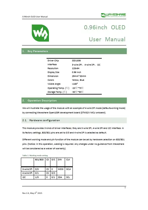
0.96inch OLEDUser Manual 1.Driver Chip SSD1306Interface 3-wire SPI、4-wire SPI、I2CResolution 128x64Display Size 0.96 inchDimension 29mm*33mmColors Yellow, BlueVisible Angle >160°Operating Temp. (℃) -20℃~70℃Storage Temp. (℃) -30℃~80℃2.We will illustrate the usage of the module with an example of 4-wire SPI mode (defaultworking mode) by connecting Waveshare Open103R development board (STM32V MCU onboard).2.1.Hardware configurationThis module provides 3 kinds of driver interfaces; they are 3-wire SPI, 4-wire SPI and I2C interface. In its factory settings, BS0/BS1 pins are set to 0/0 and 4-wire SPI is selected as default.Different working mode and pin function of the module can be set by hardware selection on BS0/BS1 pins. (Notice: In this operation, welding is required. Any changes under no guidance from Waveshare will be considered as a waiver of warranty).Table 1: Working mode setting122.2.Software configurationOpen the project file .\IDE\ OLED.uvproj in Keil, navigate to the following text, delete the ‘//’ (Double slash) before #define INTERFACE_4WIRE_SPI After compiling successfully, download the project to Open103R development board. Note: You should delete the ‘//’ (Double slash) corresponding to the mode selection2.3. Hardware connectionsConnect module to the SPI2 interface of Open103R development board, power up. OLED displays information as Figure 1 shows.Figure 1: OLED information display3. 4-wire SPI and I2C interfaces of SSD1306 OLEDThis module provides 3 kinds of driver interfaces. We introduce 4-wire SPI and I2C interfaceshere. You can read Chap. 8.1 from SSD1306-Revision_1.1.pdf for more details.The 4-wire serial interface consists of serial clock: SCLK, serial data: SDIN, D/C#, CS#. In 4-wire SPI mode,D0 acts as SCLK, D1 acts as SDIN. For the unused data pins, D2 should be left open. The pins from D3 to D7, E and R/W# (WR#)# can be connected to an external ground.Table 2: 4-wire SPI Control pins of 4-wire Serial interfaceNote(1) H stands for HIGH in signal(2) L stands for LOW in signalSDIN is shifted into an 8-bit shift register on every rising edge of SCLK in the order of D7, D6 0D/C# is sampled on every eighth clock and the data byte in the shift register is written to the Graphic Display Data RAM (GDDRAM) or command register in the same clock.Under serial mode, only write operations are allowed.Figure 2: Write procedure in 4-wire Serial interface modeThe I2C-bus interface gives access to write data and command into the device. Please referto Figure 2 for the write mode of I2C-bus in chronological order.a)Slave address bit (SA0)SSD1306 has to recognize the slave address before transmitting or receiving any information by the I2C-bus. The device will respond to the slave address following by the slave address bit (“SA0”bit) and the read/write select bit (“R/W#” bit) with the following byte format,b7 b6 b5 b4 b6 b2 b1 b00 1 1 1 1 0 SA0 R/W#“SA0” bit provides an extension bit for the slave address. Either “0111100” or3“0111101”, can be selected as the slave address of SSD1306. D/C# pin acts as SA0 for slave address selection. “R/W#” bit is used to determine the operation mode of the I2C-bus interface.R/W#=1, it is in read mode. R/W#=0, it is in write mode.b)I2C-bus data signal (SDA)SDA acts as a communication channel between the transmitter and the receiver. The data and the acknowledgement are sent through the SDA.It should be noticed that the ITO track resistance and the pulled-up resistance at “SDA” pinbecomes a voltage potential divider. As a result, the acknowledgement would not be possible to attain a valid logic 0 level in “SDA””SDAIN” and “SDAOUT” are tied together and serve as SDA. The “SDAIN” pin must be connected to act as SDA. The “SDAOUT” pin may be disconnected. When “SDAOUT” pin is disconnected, the acknowledgement signal will be ignored in the I2C-bus.c)I2C-bus clock signal (SCL)The transmission of information in the I2C-bus is following a clock signal, SCL. Each transmission of data bit is taken place during a single clock period of SCL.Table 3. I2C I2C-bus data format1)The slave address is following the start condition for recognition use. For the SSD1306, the slaveaddress is either “b0111100” or “b0111101” by changing the SA0 to LOW or HIGH (D/C pin acts as SA0).2)The write mode is established by setting the R/W# bit to logic “0”43)An acknowledgement signal will be generated after receiving one byte of data, including theslave address and the R/W# bit.4)After the transmission of the slave address, either the control byte or the data byte may be sentacross the SDA. A control byte mainly consists of Co and D/C# bits following by six “0” ‘s.a)If the Co bit is set as logic “0”, the transmission of the following information will containdata bytes only.b)The D/C# bit determines the next data byte is acted as a command or a data. If the D/C# bitis set to logic “0”, it defines the following data byte as a command. If the D/C# bit is set tologic “1”, it defines the following data byte as a data which will be stored at the GDDRAM.The GDDRAM column address pointer will be increased by one automatically after eachdata write.5)Acknowledge bit will be generated after receiving each control byte or data byte.5。
基于Arduino控制的OLED显示模块的电子实践教学研究*王红敏1,王燕1,刘军强2,宁生科1(1.西安工业大学工业中心,陕西西安710021;2.西安工业大学机电工程学院,陕西西安710021)Arduino开源平台[1]的应用为我校电子类专业创新人才的培养提供了新的方向。
其具有价格低廉、编程简单、应用方便、强扩展能力,且不需要过于深厚的理论知识作为开发基础等诸多优点,使得项目开发过程中的原型制作更加快捷简单。
因此,在实践应用中,学生可以自主挖掘日常生活或工业生产中的潜在需求,完全不会受到理论知识的限制,通过Arduino开源平台快速制作原型来进行验证,并在此基础上进行方案的持续优化。
整个实践[2]形成一个新鲜有趣的创新思维的迭代过程,从而激发学生的学习兴趣,培养创新工程实践能力。
OLED被称为有机发光显示器(Organic lighting emitting device,OLED),其具有自发光、响应时间短、低功耗、高亮度、工作温度范围宽、抗震性好以及轻薄等特点,已经在中小尺寸显示领域得到快速的发展。
并且OLED与以CRT为代表的第一代显示器和以LCD为代表的第二代显示器相比,有着明显的技术优势,已逐渐取代传统LCD显示屏在电子实践教学环节的主流地位,并广泛应用于智能家电、通信、军工、工业仪器仪表及大学生科技竞赛等领域。
针对OLED显示屏的广泛应用及适用前沿技术的发展,我校对传统电子工艺实习课程进行转型优化,对课程内容、实验设置等方面进行了调整。
2018年开始应用0.96寸OLED显示模块等实验装置,并开设出利用Arduino开源平台控制OLED显示屏的综合性、设计性实践项目[3],为学生提供了多样性选择,提高了综合性、设计性实验内容的比例,培养了学生的自主创新能力。
一、OLED显示模块的工作原理在基于Arduino的实验教学中开发的液晶显示主要采用支持众多图形显示的OLED显示模块[4],0.96寸OLED 是目前最常见的图形液晶显示器,该模块分辨率为128像素伊64像素,也称为12864OLED。
0.96寸OLED显示屏使用手册前言随着科技的不断发展,OLED显示屏作为一种新型的显示技术已经逐渐成为各种电子产品的标配。
其色彩饱和度高、对比度优秀、响应速度快等特点,使得它在智能穿戴设备、便携设备、医疗设备等领域得到了广泛的应用。
本手册将介绍0.96寸OLED显示屏的使用方法及注意事项,帮助用户更好地了解和操作该显示屏。
一、产品概述0.96寸OLED显示屏是一种小尺寸的OLED显示屏,通常用于智能手环、智能手表、可穿戴设备、小型医疗设备等产品中。
它采用了OLED(有机发光二极管)技术,具有超薄、低功耗、高对比度等特点,能够在低电压下实现高亮度显示。
该显示屏具有128x64像素的分辨率,支持SPI和I2C两种通信方式,便于与各种微控制器或单片机进行连接。
二、使用准备在使用0.96寸OLED显示屏之前,首先需要准备以下设备和材料:1. 0.96寸OLED显示屏模块2. 微控制器或单片机(例如Arduino、Raspberry Pi等)3. 杜邦线或排针4. 电源供应器(如果需要外部供电)三、连接方法0.96寸OLED显示屏通常通过SPI或I2C接口与微控制器或单片机连接。
以下是连接方法的具体步骤:1. 将0.96寸OLED显示屏模块的VCC引脚接到电源正极,将GND引脚接到电源负极,确保接线正确并稳固。
2. 根据所采用的通信方式,将SCL和SDA引脚(对于I2C通信方式)或DC和RES引脚(对于SPI通信方式)连接到微控制器或单片机相应的引脚上。
3. 如需外部供电,连接合适的电源供应器并接通电源。
四、调试与显示连接完成后,可以通过编写程序来控制0.96寸OLED显示屏的显示内容。
以下是一个简单的Arduino示例代码:```#include <Wire.h>#include <Adafruit_GFX.h>#include <Adafruit_SSD1306.h>#define OLED_RESET -1Adafruit_SSD1306 display(128, 64, &Wire, OLED_RESET);void setup() {display.begin(SSD1306_SWITCHCAPVCC, 0x3C);display.display();delay(2000);display.clearDisplay();}void loop() {display.setTextSize(1);display.setTextColor(SSD1306_WHITE);display.setCursor(0,0);display.println("Hello, World!");display.display();delay(1000);display.clearDisplay();}```通过以上示例代码,您可以实现在0.96寸OLED显示屏上显示“Hello, World!”的效果。

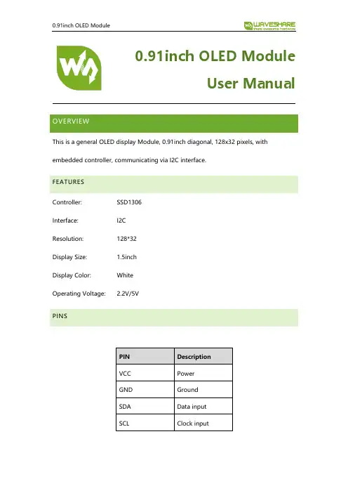
0.91inch OLED ModuleUser ManualOVERVIEWThis is a general OLED display Module, 0.91inch diagonal, 128x32 pixels, with embedded controller, communicating via I2C interface.FEATURESController: SSD1306Interface: I2CResolution: 128*32Display Size: 1.5inchDisplay Color: WhiteOperating Voltage: 2.2V/5VPINSPIN DescriptionVCC PowerGND GroundSDA Data inputSCL Clock inputWORKING PROTOCOLSSD1306 is a controller for 128*64 OLED. This OLED has only 128*32 pixels, so it uses part of SSD1306’s buffer.In theory, the OLED supports 8-bit 8080, 8-bits 6800, 3-wires SPI, 4-wires SPI and I2C, however, to save IO resources and because of the small size of OLED, we only pinout I2C interface.I2C COMMUNICATIONWhen working, MCU will first send a byte that the first 7bits are address of slave device and 1 bit write/read bit, and wait for response.After received response from slave device, MCU will send a control byte, this byte defined the data following is command or data.Slave response again, if sending command, MCU will send the command which is one byte. If sending data, MCU will sending dataFor more details about I2C, please refer to Datasheet Page20 Figure 8-7We provide STM32, Arduino and Raspberry Pi demo code for this module. The demo code will release basic functions that: draw point, draw line, draw rectangle, draw circle.STM32 DEMO CODE1.Hardware configurationDevelopment board: XNUCLEO-F103RB2.Project files:Project is compiled in MDK-ARM v5, generated by STM32CubeMX../Src:Adafruit_SSD1306.cpp: Bottom interface of OLED, provide functions that OLED initialize, basic display pixels and configure;Adafruit_GFX.cpp: Application function of OLED, provide display, drawingfunctions.glcdfont.h: LCD font, provide English fonts which size 6*8 and 8*16 RASPBERRY PI CODE1.Hardware connection2.Enable I2Csudo raspi-configchoose Interfacing Options->I2C ->Yes3.Libraries installationAbout how to install I2C libraries, you can refer to Waveshare Wiki:https:///wiki/Libraries_Installation_for_RPiingCopy demo code which you can download from Wiki to Raspberry Pi. The demo code we described are all copied to /home/pia)BCM2835(1) Install bcm2835 libraries(2) use ls command to list the files:bin:./o filesFonts: Include five fonts filesObj: project files are saved here, include main.c, OLED_Driver.c,OLED_Config.c, OLED_GUI.c and their header files.mian.c: main functionOLED_Config.c: Hardware configuration, define pins and communication type OLED_Driver.c: Hardware (OLED) driver.OLED_GUI.c: Application functions, included functions that draw point, line, rectangle, display string, pictures and so on.Show_Pic.h: Pictures data which are used to display. You should convert your pictures to data. (description in net chapter)oled_0in91: executable files, generated by command makeTo run this code, you can execute the command: sudo ./oled_0in91b)WiringPi(1) Install WiringPi libraries(2) use ls command to list the files:The folders included are similar to BCM2835’s. The only differences are that: - WiringPi oprates by read/write the device files of Linux OS. and thebcm2835 is library function of Raspberry Pi’s CPU, it operates registersdirectly. Thus, if you have used bcm2835 libraries firstly, the usage of WiringPi code will be failed. In this case, you just need to reboot the system and try again.- Due to the first difference, they underlying configuration are different. In DEV_Config.c, use wiringpiPi and the corresponding wiringPiSPI to provideunderlay interfaces.To run the code, use the command: sudo ./oled_0in91c)Python(1) use ls command to list the files:(2) Here we used Adafruit librariesbefore run code, you need to install llibraries as below:sudo apt-get updatesudo apt-get install build-essential python-dev python-pipsudo pip install RPi.GPIOsudo apt-get install python-imaging python-smbus(3) Enter directory of python code, execute commands:sudo python Adafruit_Python_SSD1306/setup.py installsudo python stats.pyd)Auto-runTo make the code run automatically after booting, you can configure/etc/rc.local file:sudo vim /etc/rc.localAdd a statement in front of exit 0:sudo python /home/pi/0in91/python/stats.py &Note that if you put the code to different directory, you need to change thepath: /home/pi/ to the correct one. & is necessary at the end, otherwise, youmay cannot login to Raspberry Pi and need to re-burn image)ARDUINO CODE1.Hardware ConnectionDevelopment board: UNO PLUS2.Files Description:../oled:oled.ino: Project file of Arduino, double click to openProject directory:Adafruit_SSD1306.cpp: Bottom interfaces of OLED, includes OLED initialize, basic display and configuration functions.Adafruit_GFX.cpp:Application functions of OLEDAdafruit_SSD1306.h、Adafruit_GFX.h: Header filesglcdfont.h:LCD font, provide English fonts which size 6*8 and 8*163.RunningBefore running the code, you should copy the libraries files of this project to the libraries directory of IDE, which is under the installation directory of Arduino IDE.Note that you cannot put files directly to the libraries directory, you need to save them on a folder, for example 0in91_OLED_Module as below:Then, open olde.ino then download the codeUse software Image2Lcd to open picture (Monochrome picture) and configure: 输出数据类型(Data types):C语言数据(*.c)扫描方式(Scanning way):数据水平(data horizonal),字节垂直(byte vertical) 输出灰度(gray scale):单色(monochrome)最大宽度和高度(height and width):128 32 (Resolution of OLED)And then check the option that color invert.。
0.96寸OLED显示屏一、OLED简介OLED,即有机发光二级管(Organic Light Emitting Diode)。
OLED由于同时具备自发光,不需背光源、对比度高、厚度薄、视角广、反应速度快、可用于扭曲性面板、使用温度范围广、构造及制作较简单等优异的特性,被认为是下一代的平面显示器新兴应用技术。
LCD都需要背光,而OLED不需要,因为它是自发光的。
这样同样的显示,OLED效果要来得好一些。
以目前的技术,OLED的尺寸还难以大型化,但是分辨率确可以做到很高。
在此我们使用的是中景园电子的0.96寸OLED显示屏,该屏有以下特点:1、0.96寸OLED有黄蓝、白、蓝三种颜色可以选择,其中黄蓝是屏上1/4部分为黄光,下3/4位蓝光,而且是固定区域显示固定颜色,颜色和显示区域均不能修改。
白光则为纯白,也就是黑底白字。
蓝光则为纯蓝,也就是黑底蓝字。
2、分辨率为128*64,每个像素都是一个LED。
3、多种接口方式,OLED裸屏的接口方式有5种:6800、8080两种并行接口方式、3线或4线的串行SPI接口方式、I2C接口方式(只需要用到2根线就可以控制OLED了!),这5种接口方式是通过屏上的BS0~BS2来配置的。
4、中景园电子的屏开发了两种接口的DEMO板,接口分别为七针的SPI/I2C兼容模块,四针的I2C模块,两种模块都很方便使用,我们可以根据实际需求来选择不同的模块。
二、模块特点:1、0.96寸OLED裸屏外观裸屏为30Pin,从屏正面看左下角为1脚,右下角为30脚。
在设计的时候一定要注意不要弄反了。
具体的接口方式请大家查看0.96寸OLED官方数据手册,里面有详细介绍。
2、0.96寸OLED模块(1)SPI/I2C接口模块(7脚)(2)I2C接口模块(4脚)3、0.96寸OLED的驱动IC芯片(SSD1306)本屏所用的驱动IC芯片为SSD1306,其具有内部升压功能,所以在设计的时候就不需要再专门设计升压电路了。
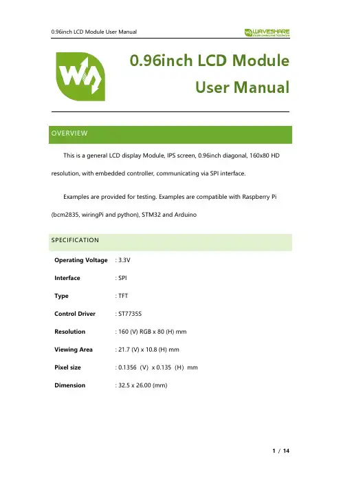
0.96inch LCD ModuleUser ManualOVERVIEWThis is a general LCD display Module, IPS screen, 0.96inch diagonal, 160x80 HD resolution, with embedded controller, communicating via SPI interface.Examples are provided for testing. Examples are compatible with Raspberry Pi (bcm2835, wiringPi and python), STM32 and ArduinoSPECIFICATIONOperating Voltage : 3.3VInterface : SPIType : TFTControl Driver : ST7735SResolution : 160 (V) RGB x 80 (H) mmViewing Area : 21.7 (V) x 10.8 (H) mmPixel size : 0.1356(V)x 0.135(H)mmDimension : 32.5 x 26.00 (mm)PINOUTOverview (1)Specification (1)Pinout (2)Hardware (5)Controller (5)Communication protocol (5)Demo codes (7)Download (7)Raspberry Pi (7)Copy to Raspberry Pi (7)Libraries install (8)Hardware connection (10)Running examples (10)Expected result (11)STM32 (12)Hardware connection (12)Expected result (12)Arduino (13)Hardware connection (13)Expected result (13)FAQ (14)CONTROLLERST7735S is a controller for 162 x RGB x132 LCD. Note that the resolution of this LCD module is 160(H)RGBx80(V) indeed.ST7735S supports RGB444, RGB565 and RGB666 three formats. This LCD module we use RGB565.Because that the first pixel of the LCD is different with the origin point of controller, therefore, we should offset the position when initialize the module: Horizontal: begin from the second pixel; Vertical: begin from the 27th pixel. Make sure that the display position of LCD is same as RAM.For most of the LCD controller, there are several interfaces for choosing, this module we use SPI interface which is fast and simple.COMMUNICATION PROTOCOLNote: It is not like the tradition SPI protocol, it only uses MOSI to send data from master to slave for LCD display. For details please refer to Datasheet Page 105. RESX: Reset, should be pull-down when power on, set to 1 other time.CSX: Slave chip select. The chip is enabled only CS is set LowD/CX: Data/Command selection; DC=0, write command; DC=1, write dataSDA: Data transmitted. (RGB data)SCL: SPI clockThe SPI communication protocol of the data transmission uses control bits: clock phase (CPHA) and clock polarity (CPOL):CPOL defines the level while synchronization clock is idle. If CPOL=0, then it is LOW. CPHA defines at wh ish clock’s tick the data transmission starts. CPHL=0 – at the first one, otherwise at the second oneThis combination of two bits provides 4 modes of SPI data transmission. The commonly used is SPI0 mode, i.e. GPHL=0 and CPOL=0.According to the figure above, data transmitting begins at the first falling edge, 8bit data are transmitted at one clock cycle. It is SPI0. MSB.DOWNLOADVisit Waveshare wiki and search for 0.96inch LCD Module. Download the demo code:Extract and get the folders as below:Arduino: For Arduino UNORaspberry Pi: Includes three examples, BCM2835, WiringPi and PythonSTM32: For XNUCLEO-F103RB, which integrate STM32F103RBT6RASPBERRY PICOPY TO RASPBERRY PI1.Insert SD card which has Raspbian installed to your PC2.Copy RaspberryPi extracted to root directory (BOOT) of SD card3.Power on your Raspberry Pi and open Terminal, you can find that the examples islisted in boot directory4.Copy the RaspberryPi folder to /home/pi and change its execute permission.LIBRARIES INSTALLTo use the demo codes, you need to first install librariesInstall BCM2835:xx is the version of library. For example, if the library you download is bcm2835-1.52, the command should be : sudo tar zxvf bcm2835-1.52.tar.gzInstall wiringPi:Install Python libraries:HARDWARE CONNECTIONRUNNING EXAMPLESEnter the folder: cd RaspberryPi/bcm2835 example:Press Ctrl and C to stop running wiringpi example:Press Ctrl and C to stop running python example:Press Ctrl and C to stop running EXPECTED RESULT1.Clear screen2.Display number and strings3.Draw figures4.Display 40 x 40 image5.Display 160x80 imageSTM32The development board used is XNUCLEO-F103RB, based on HAL library HARDWARE CONNECTIONEXPECTED RESULT1.Clear screen2.Display number and strings3.Draw figures4.Display 40x40 image5.Display 160x80 imageARDUINOThis example is compatible with Arduino UNO HARDWARE CONNECTIONEXPECTED RESULT1.Clear screen2.Display number and strings3.Display figures4.Display 40x40 imageFAQ1.How to control backlight?- You can use the function LCD_SetBacklight() to control the backlight2.Why the LCD is black when working with Raspberry Pia) Check if SPI interface was enabledb) Check if the BL pin work normally, if the pin has no output, please try todisconnect the BL control pin3.What does it happen if using Raspberry Pi improperly?If you run python or bcm2835 examples after wiringPi, the LCD may cannot work normally, please try to restart Raspberry Pi can try again.4.How to rotate display?-You can use the function Paint_SetRotate(Rotate) to rotate display. Rotate should be 0, 90, 180 or 270.-Python can call rotate(Rotate) function for any angle.5.Python Image library- For some of the OS, you should execute command to install python-imaging library: sudo apt-get install python-imaging。
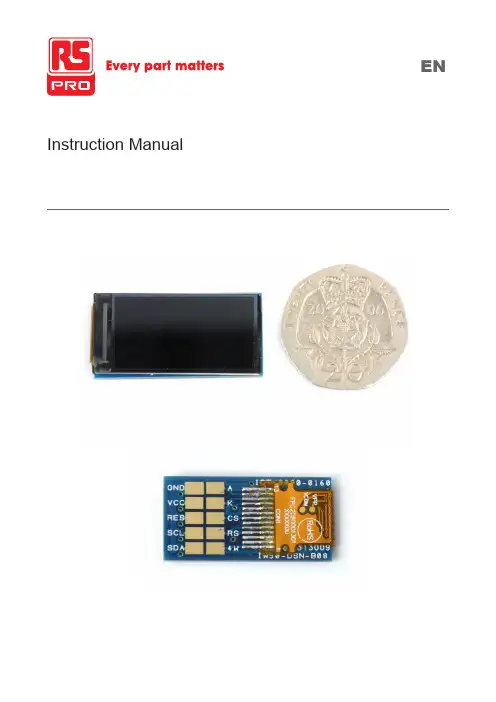
Instruction ManualOverviewAn IPS, full colour TFT module, offering 80 degree viewing angles allround, with a 500nit backlight. It is a transmissive type display operating in the normally black mode.This TFT LCD has a 0.96-inch diagonally measured active display area with 80 x 160 dot (80 horizontal by 160 vertical pixel) resolution. Each pixel is divided into Red, Green, Blue dots which are arranged in vertical stripes.Technical Specificationsz Size: 0.96 inchz Dot Matrix: 80 x RGB x 160(TFT) dotsz Module dimension: 13.5(W) x 27.95(H) x 3.00(D) mmz Active area: 10.8 x 21.696 mmz Dot pitch: 0.135 x 0.1356 mmz LCD type: TFT, Normally black, Transmissivez Viewing Angle: 80/80/80/80z Aspect Ratio: 1:2z IC: ST7735Sz Backlight Type: LED,Normally Whitez With /Without TP: Without TPz Surface: Glare*Colour tone slight changed by temperature and driving voltage.InterfacePin DefinitionTechnical DrawingAbsolute Maximum Ratings1. Temp. ≤60˚C, 90% RH MAX. Temp.>60˚C, Absolute humidity shall be less than 90% RH at 60˚C.Electrical CharacteristicsOperating conditions:Note 1 : There are 1 Groups LEDNote 2 : Ta = 25 ˚CNote 3 : Brightness to be decreased to 50% of the initial valueNote 4 : The single LED lamp caseData Colour Coding3-Wire SPI Mode: RGB 5-6-5-bit Input, 65K-Colours, 3AH=“05h”Look-up table for 65k colour mapping (16 bits to 18 bits) Note 1: Pixel data with the 16-bit colour depth informationNote 2: The most significant bits are: Rx4, Gx5 and Bx4Note 3: The least significant bits are: Rx0, Gx0 and Bx04-Wire SPI Mode: RGB 5-6-5-bit Input, 65K-Colours, 3AH=“05h”Look-up table for 65k colour mapping (16 bits to 18 bits) Note 1. Pixel data with the 16-bit colour depth informationNote 2. The most significant bits are: Rx4, Gx5 and Bx4Note 3. The least significant bits are: Rx0, Gx0 and Bx0Display Options availableTFT display as a stand-alone itemDisplay on pcb with mountingOptical CharacteristicsTa=25±2˚CNote 1: Definition of viewing angle rangeNote 2: Test equipment setup:After stabilizing and leaving the panel alone at a driven temperature for 10 minutes, the measurement should be executed. Measurement should be executed in a stable, windless, and dark room. Optical specifications are measured by Topcon BM-7orBM-5 luminance meter 1.0° field of view at a distance of 50cm and normal direction.Note 3: Definition of Response time:The response time is defined as the LCD optical switching time interval between “White” state and “Black” state. Rise time, Tr, is the time between photo detector output intensity changed from 90%to 10%.Black(TFT ON)White(TFT OFF)White(TFT OFF)100%90%10%0%DisplayNote 4: Definition of contrast ratio:The contrast ratio is defined as the following expression.Luminance measured when LCD on the “White” state Contrast ratio (CR) = Luminance measured when LCD on the “Black” stateNote 5: White Vi = Vi50 ± 1.5V Black Vi = Vi50 ± 2.0V“±” means that the analog input signal swings in phase with VCOM signal.“±” means that the analog input signal swings out of phase with VCOM signal.The 100% transmission is defined as the transmission of LCD panel when all the input terminals of module are electrically opened.Note 6: Definition of colour chromaticity (CIE 1931)Colour coordinates measured at the center point of LCDNote 7: Measured at the center area of the panel when all the input terminals of LCD panel are electrically opened.ReliabilityContent of Reliability Test (Wide temperature, -20˚C~70˚C)Environmental TestNote1: No dew condensation to be observed.Note2: The function test shall be conducted after 4 hours storage at the normal Temperature and humidity after remove from the test chamber.Note3: The packing have to including into the vibration testing.。
中景园电子0.96OLED显示屏_模块说明书
一、OLED技术特点
(1)OLED 器件的核心层厚度很薄,厚度可以小于1mm,为液晶的1/3。
(2)OLED 器件为全固态机构,无真空,液体物质,抗震性好,可以适应巨大的加速度,振动等恶劣环境。
(3)主动发光的特性使OLED 几乎没有视角限制,视角一般可达到170 度,具有较宽的视角,从侧面也不会失真。
(4)OLED 显示屏的响应时间超过TFT—LCD 液晶屏。
TFT—LCD 的响应时间大约是几十毫秒,现在做得最好的TFT—LCD 响应时间也只有12 毫秒。
而OLED 显示屏的响应时间大约是几微秒到几十微秒。
(5)OLED 低温特性好,在零下40 摄氏度都能正常显示,目前航天服上也使用OLED 作为显示屏。
而TFT—LCD 的响应速度随温度发生变化,低温下,其响应速度变慢,因此,液晶在低温下显示效果不好。
(6)OLED 采用有机发光原理,所需材料很少,制作上比采用液体发光的液晶工序少,液晶显示屏少 3 道工序,成本大幅降低。
(7)OLED 采用的二极管会自行发光,因此不需要背面光源,发光转化效率高,能耗比液晶低,OLED 能够在不同材质的基板上制造,厂家甚至可以将电路印刷在弹性材料上——做成能弯曲的柔软显示器。
(8)低电压直流驱动,5V 以下,用电池就能点亮。
高亮度,可达300 明流以上。
OLED显示模块驱动原理及应用本文以中景园OLED显示模块为例,介绍模块的应用和OLED显示及驱动的基本原理。
文中介绍了显示模块、SSD1306驱动芯片以及GT20L16S1Y字库芯片相关技术内容及原理,并加上了作者的理解和应用记录。
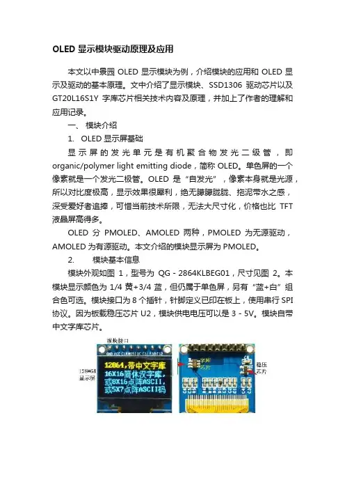
一、模块介绍1. OLED显示屏基础显示屏的发光单元是有机聚合物发光二级管,即organic/polymer light emitting diode,简称 OLED。
单色屏的一个像素就是一个发光二极管。
OLED是“自发光”,像素本身就是光源,所以对比度极高,显示效果很犀利,绝无朦朦胧胧、拖泥带水之感,深受爱好者追捧,可惜当前技术所限,无法大尺寸化,价格也比TFT 液晶屏高得多。
OLED分PMOLED、AMOLED两种,PMOLED为无源驱动,AMOLED为有源驱动。
本文介绍的模块显示屏为PMOLED。
2. 模块基本信息模块外观如图1,型号为QG-2864KLBEG01,尺寸见图2。
本模块显示颜色为1/4黄+3/4蓝,但仍属于单色屏,另有“蓝+白”组合色可选。
模块接口为8个插针,针脚定义已印在板上,使用串行SPI 协议。
因为板载稳压芯片U2,模块供电电压可以是3-5V。
模块自带中文字库芯片。
图1.模块正面及反面图2.模块尺寸图3. 模块器件及元件简介1) OLED显示屏:128*64点阵OLED单色屏。
下文简称为显示屏、屏、OLED屏。
2) SSD1306驱动芯片:模块上直接看不到,芯片封装在显示屏背面玻璃基板上。
3) GT20L16S1Y字库芯片:内部固化了8套字符的点阵数据,90%的容量都用来存储中文字库。
4) 接口及电源配置电路:8路插针,板载低压差降压稳压芯片662K。
5) PCB板及若干外围电阻电容元件。
模块厂家已做好外围电路,不用再操心硬件电路。
4. 模块电路图图3、模块电原理图供电:模块供电输入端为VCC_IN,经U2降压后供U1、U4等电路。
OLED屏驱动需要7-7.5V电压,由SSD1306内置电荷泵升压后提供。
0.96寸OLED显示屏介绍0.96 寸OLED 显示屏使用方法(以中景园电子的0.96 寸OLED 显示屏为例)0.96寸OLED显示屏实物图七针SPI/IIC 0.96寸OLED显示屏使用方法:七针SPI/IIC 0.96寸OLED显示屏共有七个管脚,1~7 分别为GDN、VCC、D0、D1、RES、DC、CS。
此模块支持四线SPI、三线SPI、IIC 接口。
0.96寸OLED显示屏裸屏是支持五种不同接口的,除了前面的三种还有6800、8080 并口方式;由于这两种接口占用数据线比较多;而且不太常用,所以模块在设计的时候没有引出来。
模块的通信接口是通过BS0,BS1,BS2三个管脚来配置的。
在SPI 接口中,R1,R2,R8 三个电阻是不焊接的。
在IIC 接口中,需要将R3换到R1上,R8 可以焊接也可不焊接。
七针SPI/IIC 0.96寸OLED显示屏正面丝印如下,如果想用IIC接口,在IIC接口中需要将RES接高电平,可以与VCC对接,使OLED复位脚一直操持高电平,也就是不复位的状态;同时需要将DC,CS 接电源地;IIC 通信中只需要GND ,VCC,D0(时钟信号),D1(数据信号)四根线。
如果感觉比较麻烦;也可以直接选用四针的IIC接口的0.96寸OLED显示屏。
四针IIC接口相对比较简单一些,只有两个信号线。
1、GND:电源地。
2、VCC:电源正(3~5.5V)。
3、SCL:OLED 的D0 脚,在IIC 通信中为时钟管脚。
4、SDA:OLED 的D1 脚,在IIC 通信中为数据管脚。
0.96 寸OLED显示屏例程:/****************0.96英寸OLED显示信息***************** 处理器:STM32F103C8T6程序功能:开发板上电后在oled液晶屏中显示一些提示信息。
*****************************************************/ #include "sys.h"#include "stdlib.h"#define OLED_RST_Clr() PCout(13)=0 //RST#define OLED_RST_Set() PCout(13)=1 //RST#define OLED_RS_Clr() PBout(4)=0 //DC#define OLED_RS_Set() PBout(4)=1 //DC#define OLED_SCLK_Clr() PCout(15)=0 //SCL#define OLED_SCLK_Set() PCout(15)=1 //SCL#define OLED_SDIN_Clr() PCout(14)=0 //SDA#define OLED_SDIN_Set() PCout(14)=1 //SDA#define OLED_CMD 0 //写命令#define OLED_DATA 1 //写数据void delay_init(u8 SYSCLK);void delay_ms(u16 nms);void delay_us(u32 nus);void OLED_WR_Byte(u8 dat,u8 cmd);void OLED_Display_On(void);void OLED_Display_Off(void);void OLED_Refresh_Gram(void);void Oled_Init(void);void OLED_Clear(void);void OLED_DrawPoint(u8 x,u8 y,u8 t);void OLED_ShowChar(u8 x,u8 y,u8 chr,u8 size,u8 mode); void OLED_ShowNumber(u8 x,u8 y,u32 num,u8 len,u8 size); void OLED_ShowString(u8 x,u8 y,const u8 *p);void Oled_Show(void);u8 OLED_GRAM[128][8];const unsigned char oled_asc2_1206[95][12]={{0x00,0x00,0x00,0x00,0x00,0x00,0x00,0x00,0x00,0x00,0x00,0x00},/*" ",0*/ {0x00,0x00,0x00,0x00,0x3F,0x40,0x00,0x00,0x00,0x00,0x00,0x00},/*"!",1*/ {0x00,0x00,0x30,0x00,0x40,0x00,0x30,0x00,0x40,0x00,0x00,0x00},/*""",2*/ {0x09,0x00,0x0B,0xC0,0x3D,0x00,0x0B,0xC0,0x3D,0x00,0x09,0x00},/*"#",3*/ {0x18,0xC0,0x24,0x40,0x7F,0xE0,0x22,0x40,0x31,0x80,0x00,0x00},/*"$",4*/ {0x18,0x00,0x24,0xC0,0x1B,0x00,0x0D,0x80,0x32,0x40,0x01,0x80},/*"%",5*/ {0x03,0x80,0x1C,0x40,0x27,0x40,0x1C,0x80,0x07,0x40,0x00,0x40},/*"&",6*/ {0x10,0x00,0x60,0x00,0x00,0x00,0x00,0x00,0x00,0x00,0x00,0x00},/*"'",7*/ {0x00,0x00,0x00,0x00,0x00,0x00,0x1F,0x80,0x20,0x40,0x40,0x20},/*"(",8*/ {0x00,0x00,0x40,0x20,0x20,0x40,0x1F,0x80,0x00,0x00,0x00,0x00},/*")",9*/ {0x09,0x00,0x06,0x00,0x1F,0x80,0x06,0x00,0x09,0x00,0x00,0x00},/*"*",10*/ {0x04,0x00,0x04,0x00,0x3F,0x80,0x04,0x00,0x04,0x00,0x00,0x00},/*"+",11*/ {0x00,0x10,0x00,0x60,0x00,0x00,0x00,0x00,0x00,0x00,0x00,0x00},/*",",12*/ {0x04,0x00,0x04,0x00,0x04,0x00,0x04,0x00,0x04,0x00,0x00,0x00},/*"-",13*/ {0x00,0x00,0x00,0x40,0x00,0x00,0x00,0x00,0x00,0x00,0x00,0x00},/*".",14*/ {0x00,0x20,0x01,0xC0,0x06,0x00,0x38,0x00,0x40,0x00,0x00,0x00},/*"/",15*/ {0x1F,0x80,0x20,0x40,0x20,0x40,0x20,0x40,0x1F,0x80,0x00,0x00},/*"0",16*/ {0x00,0x00,0x10,0x40,0x3F,0xC0,0x00,0x40,0x00,0x00,0x00,0x00},/*"1",17*/ {0x18,0xC0,0x21,0x40,0x22,0x40,0x24,0x40,0x18,0x40,0x00,0x00},/*"2",18*/ {0x10,0x80,0x20,0x40,0x24,0x40,0x24,0x40,0x1B,0x80,0x00,0x00},/*"3",19*/ {0x02,0x00,0x0D,0x00,0x11,0x00,0x3F,0xC0,0x01,0x40,0x00,0x00},/*"4",20*/ {0x3C,0x80,0x24,0x40,0x24,0x40,0x24,0x40,0x23,0x80,0x00,0x00},/*"5",21*/ {0x1F,0x80,0x24,0x40,0x24,0x40,0x34,0x40,0x03,0x80,0x00,0x00},/*"6",22*/ {0x30,0x00,0x20,0x00,0x27,0xC0,0x38,0x00,0x20,0x00,0x00,0x00},/*"7",23*/ {0x1B,0x80,0x24,0x40,0x24,0x40,0x24,0x40,0x1B,0x80,0x00,0x00},/*"8",24*/ {0x1C,0x00,0x22,0xC0,0x22,0x40,0x22,0x40,0x1F,0x80,0x00,0x00},/*"9",25*/ {0x00,0x00,0x00,0x00,0x08,0x40,0x00,0x00,0x00,0x00,0x00,0x00},/*":",26*/ {0x00,0x00,0x00,0x00,0x04,0x60,0x00,0x00,0x00,0x00,0x00,0x00},/*";",27*/ {0x00,0x00,0x04,0x00,0x0A,0x00,0x11,0x00,0x20,0x80,0x40,0x40},/*"<",28*/ {0x09,0x00,0x09,0x00,0x09,0x00,0x09,0x00,0x09,0x00,0x00,0x00},/*"=",29*/ {0x00,0x00,0x40,0x40,0x20,0x80,0x11,0x00,0x0A,0x00,0x04,0x00},/*">",30*/ {0x18,0x00,0x20,0x00,0x23,0x40,0x24,0x00,0x18,0x00,0x00,0x00},/*"?",31*/ {0x1F,0x80,0x20,0x40,0x27,0x40,0x29,0x40,0x1F,0x40,0x00,0x00},/*"@",32*/ {0x00,0x40,0x07,0xC0,0x39,0x00,0x0F,0x00,0x01,0xC0,0x00,0x40},/*"A",33*/ {0x20,0x40,0x3F,0xC0,0x24,0x40,0x24,0x40,0x1B,0x80,0x00,0x00},/*"B",34*/ {0x1F,0x80,0x20,0x40,0x20,0x40,0x20,0x40,0x30,0x80,0x00,0x00},/*"C",35*/ {0x20,0x40,0x3F,0xC0,0x20,0x40,0x20,0x40,0x1F,0x80,0x00,0x00},/*"D",36*/ {0x20,0x40,0x3F,0xC0,0x24,0x40,0x2E,0x40,0x30,0xC0,0x00,0x00},/*"E",37*/ {0x20,0x40,0x3F,0xC0,0x24,0x40,0x2E,0x00,0x30,0x00,0x00,0x00},/*"F",38*/ {0x0F,0x00,0x10,0x80,0x20,0x40,0x22,0x40,0x33,0x80,0x02,0x00},/*"G",39*/ {0x20,0x40,0x3F,0xC0,0x04,0x00,0x04,0x00,0x3F,0xC0,0x20,0x40},/*"H",40*/ {0x20,0x40,0x20,0x40,0x3F,0xC0,0x20,0x40,0x20,0x40,0x00,0x00},/*"I",41*/ {0x00,0x60,0x20,0x20,0x20,0x20,0x3F,0xC0,0x20,0x00,0x20,0x00},/*"J",42*/ {0x20,0x40,0x3F,0xC0,0x24,0x40,0x0B,0x00,0x30,0xC0,0x20,0x40},/*"K",43*/{0x20,0x40,0x3F,0xC0,0x20,0x40,0x00,0x40,0x00,0x40,0x00,0xC0},/*"L",44*/ {0x3F,0xC0,0x3C,0x00,0x03,0xC0,0x3C,0x00,0x3F,0xC0,0x00,0x00},/*"M",45*/ {0x20,0x40,0x3F,0xC0,0x0C,0x40,0x23,0x00,0x3F,0xC0,0x20,0x00},/*"N",46*/ {0x1F,0x80,0x20,0x40,0x20,0x40,0x20,0x40,0x1F,0x80,0x00,0x00},/*"O",47*/ {0x20,0x40,0x3F,0xC0,0x24,0x40,0x24,0x00,0x18,0x00,0x00,0x00},/*"P",48*/ {0x1F,0x80,0x21,0x40,0x21,0x40,0x20,0xE0,0x1F,0xA0,0x00,0x00},/*"Q",49*/ {0x20,0x40,0x3F,0xC0,0x24,0x40,0x26,0x00,0x19,0xC0,0x00,0x40},/*"R",50*/ {0x18,0xC0,0x24,0x40,0x24,0x40,0x22,0x40,0x31,0x80,0x00,0x00},/*"S",51*/ {0x30,0x00,0x20,0x40,0x3F,0xC0,0x20,0x40,0x30,0x00,0x00,0x00},/*"T",52*/ {0x20,0x00,0x3F,0x80,0x00,0x40,0x00,0x40,0x3F,0x80,0x20,0x00},/*"U",53*/ {0x20,0x00,0x3E,0x00,0x01,0xC0,0x07,0x00,0x38,0x00,0x20,0x00},/*"V",54*/ {0x38,0x00,0x07,0xC0,0x3C,0x00,0x07,0xC0,0x38,0x00,0x00,0x00},/*"W",55*/ {0x20,0x40,0x39,0xC0,0x06,0x00,0x39,0xC0,0x20,0x40,0x00,0x00},/*"X",56*/ {0x20,0x00,0x38,0x40,0x07,0xC0,0x38,0x40,0x20,0x00,0x00,0x00},/*"Y",57*/ {0x30,0x40,0x21,0xC0,0x26,0x40,0x38,0x40,0x20,0xC0,0x00,0x00},/*"Z",58*/ {0x00,0x00,0x00,0x00,0x7F,0xE0,0x40,0x20,0x40,0x20,0x00,0x00},/*"[",59*/ {0x00,0x00,0x70,0x00,0x0C,0x00,0x03,0x80,0x00,0x40,0x00,0x00},/*"\",60*/ {0x00,0x00,0x40,0x20,0x40,0x20,0x7F,0xE0,0x00,0x00,0x00,0x00},/*"]",61*/ {0x00,0x00,0x20,0x00,0x40,0x00,0x20,0x00,0x00,0x00,0x00,0x00},/*"^",62*/ {0x00,0x10,0x00,0x10,0x00,0x10,0x00,0x10,0x00,0x10,0x00,0x10},/*"_",63*/ {0x00,0x00,0x00,0x00,0x40,0x00,0x00,0x00,0x00,0x00,0x00,0x00},/*"`",64*/ {0x00,0x00,0x02,0x80,0x05,0x40,0x05,0x40,0x03,0xC0,0x00,0x40},/*"a",65*/ {0x20,0x00,0x3F,0xC0,0x04,0x40,0x04,0x40,0x03,0x80,0x00,0x00},/*"b",66*/ {0x00,0x00,0x03,0x80,0x04,0x40,0x04,0x40,0x06,0x40,0x00,0x00},/*"c",67*/ {0x00,0x00,0x03,0x80,0x04,0x40,0x24,0x40,0x3F,0xC0,0x00,0x40},/*"d",68*/ {0x00,0x00,0x03,0x80,0x05,0x40,0x05,0x40,0x03,0x40,0x00,0x00},/*"e",69*/ {0x00,0x00,0x04,0x40,0x1F,0xC0,0x24,0x40,0x24,0x40,0x20,0x00},/*"f",70*/ {0x00,0x00,0x02,0xE0,0x05,0x50,0x05,0x50,0x06,0x50,0x04,0x20},/*"g",71*/ {0x20,0x40,0x3F,0xC0,0x04,0x40,0x04,0x00,0x03,0xC0,0x00,0x40},/*"h",72*/ {0x00,0x00,0x04,0x40,0x27,0xC0,0x00,0x40,0x00,0x00,0x00,0x00},/*"i",73*/ {0x00,0x10,0x00,0x10,0x04,0x10,0x27,0xE0,0x00,0x00,0x00,0x00},/*"j",74*/ {0x20,0x40,0x3F,0xC0,0x01,0x40,0x07,0x00,0x04,0xC0,0x04,0x40},/*"k",75*/ {0x20,0x40,0x20,0x40,0x3F,0xC0,0x00,0x40,0x00,0x40,0x00,0x00},/*"l",76*/ {0x07,0xC0,0x04,0x00,0x07,0xC0,0x04,0x00,0x03,0xC0,0x00,0x00},/*"m",77*/ {0x04,0x40,0x07,0xC0,0x04,0x40,0x04,0x00,0x03,0xC0,0x00,0x40},/*"n",78*/ {0x00,0x00,0x03,0x80,0x04,0x40,0x04,0x40,0x03,0x80,0x00,0x00},/*"o",79*/ {0x04,0x10,0x07,0xF0,0x04,0x50,0x04,0x40,0x03,0x80,0x00,0x00},/*"p",80*/ {0x00,0x00,0x03,0x80,0x04,0x40,0x04,0x50,0x07,0xF0,0x00,0x10},/*"q",81*/ {0x04,0x40,0x07,0xC0,0x02,0x40,0x04,0x00,0x04,0x00,0x00,0x00},/*"r",82*/ {0x00,0x00,0x06,0x40,0x05,0x40,0x05,0x40,0x04,0xC0,0x00,0x00},/*"s",83*/ {0x00,0x00,0x04,0x00,0x1F,0x80,0x04,0x40,0x00,0x40,0x00,0x00},/*"t",84*/ {0x04,0x00,0x07,0x80,0x00,0x40,0x04,0x40,0x07,0xC0,0x00,0x40},/*"u",85*/ {0x04,0x00,0x07,0x00,0x04,0xC0,0x01,0x80,0x06,0x00,0x04,0x00},/*"v",86*/ {0x06,0x00,0x01,0xC0,0x07,0x00,0x01,0xC0,0x06,0x00,0x00,0x00},/*"w",87*/{0x04,0x40,0x06,0xC0,0x01,0x00,0x06,0xC0,0x04,0x40,0x00,0x00},/*"x",88*/{0x04,0x10,0x07,0x10,0x04,0xE0,0x01,0x80,0x06,0x00,0x04,0x00},/*"y",89*/{0x00,0x00,0x04,0x40,0x05,0xC0,0x06,0x40,0x04,0x40,0x00,0x00},/*"z",90*/{0x00,0x00,0x00,0x00,0x04,0x00,0x7B,0xE0,0x40,0x20,0x00,0x00},/*"{",91*/{0x00,0x00,0x00,0x00,0x00,0x00,0xFF,0xF0,0x00,0x00,0x00,0x00},/*"|",92*/{0x00,0x00,0x40,0x20,0x7B,0xE0,0x04,0x00,0x00,0x00,0x00,0x00},/*"}",93*/{0x40,0x00,0x80,0x00,0x40,0x00,0x20,0x00,0x20,0x00,0x40,0x00},/*"~",94*/};const unsigned char oled_asc2_1608[95][16]={{0x00,0x00,0x00,0x00,0x00,0x00,0x00,0x00,0x00,0x00,0x00,0x00,0x00,0x00,0x00,0x00},/*" ",0*/ {0x00,0x00,0x00,0x00,0x00,0x00,0x1F,0xCC,0x00,0x0C,0x00,0x00,0x00,0x00,0x00,0x00},/*"!",1*/ {0x00,0x00,0x08,0x00,0x30,0x00,0x60,0x00,0x08,0x00,0x30,0x00,0x60,0x00,0x00,0x00},/*""",2*/ {0x02,0x20,0x03,0xFC,0x1E,0x20,0x02,0x20,0x03,0xFC,0x1E,0x20,0x02,0x20,0x00,0x00},/*"#",3*/ {0x00,0x00,0x0E,0x18,0x11,0x04,0x3F,0xFF,0x10,0x84,0x0C,0x78,0x00,0x00,0x00,0x00},/*"$",4*/ {0x0F,0x00,0x10,0x84,0x0F,0x38,0x00,0xC0,0x07,0x78,0x18,0x84,0x00,0x78,0x00,0x00},/*"%",5*/ {0x00,0x78,0x0F,0x84,0x10,0xC4,0x11,0x24,0x0E,0x98,0x00,0xE4,0x00,0x84,0x00,0x08},/*"&",6*/ {0x08,0x00,0x68,0x00,0x70,0x00,0x00,0x00,0x00,0x00,0x00,0x00,0x00,0x00,0x00,0x00},/*"'",7*/ {0x00,0x00,0x00,0x00,0x00,0x00,0x07,0xE0,0x18,0x18,0x20,0x04,0x40,0x02,0x00,0x00},/*"(",8*/ {0x00,0x00,0x40,0x02,0x20,0x04,0x18,0x18,0x07,0xE0,0x00,0x00,0x00,0x00,0x00,0x00},/*")",9*/ {0x02,0x40,0x02,0x40,0x01,0x80,0x0F,0xF0,0x01,0x80,0x02,0x40,0x02,0x40,0x00,0x00},/*"*",10*/ {0x00,0x80,0x00,0x80,0x00,0x80,0x0F,0xF8,0x00,0x80,0x00,0x80,0x00,0x80,0x00,0x00},/*"+",11*/ {0x00,0x01,0x00,0x0D,0x00,0x0E,0x00,0x00,0x00,0x00,0x00,0x00,0x00,0x00,0x00,0x00},/*",",12*/ {0x00,0x00,0x00,0x80,0x00,0x80,0x00,0x80,0x00,0x80,0x00,0x80,0x00,0x80,0x00,0x80},/*"-",13*/ {0x00,0x00,0x00,0x0C,0x00,0x0C,0x00,0x00,0x00,0x00,0x00,0x00,0x00,0x00,0x00,0x00},/*".",14*/ {0x00,0x00,0x00,0x06,0x00,0x18,0x00,0x60,0x01,0x80,0x06,0x00,0x18,0x00,0x20,0x00},/*"/",15*/ {0x00,0x00,0x07,0xF0,0x08,0x08,0x10,0x04,0x10,0x04,0x08,0x08,0x07,0xF0,0x00,0x00},/*"0",16*/ {0x00,0x00,0x08,0x04,0x08,0x04,0x1F,0xFC,0x00,0x04,0x00,0x04,0x00,0x00,0x00,0x00},/*"1",17*/ {0x00,0x00,0x0E,0x0C,0x10,0x14,0x10,0x24,0x10,0x44,0x11,0x84,0x0E,0x0C,0x00,0x00},/*"2",18*/ {0x00,0x00,0x0C,0x18,0x10,0x04,0x11,0x04,0x11,0x04,0x12,0x88,0x0C,0x70,0x00,0x00},/*"3",19*/ {0x00,0x00,0x00,0xE0,0x03,0x20,0x04,0x24,0x08,0x24,0x1F,0xFC,0x00,0x24,0x00,0x00},/*"4",20*/ {0x00,0x00,0x1F,0x98,0x10,0x84,0x11,0x04,0x11,0x04,0x10,0x88,0x10,0x70,0x00,0x00},/*"5",21*/ {0x00,0x00,0x07,0xF0,0x08,0x88,0x11,0x04,0x11,0x04,0x18,0x88,0x00,0x70,0x00,0x00},/*"6",22*/ {0x00,0x00,0x1C,0x00,0x10,0x00,0x10,0xFC,0x13,0x00,0x1C,0x00,0x10,0x00,0x00,0x00},/*"7",23*/ {0x00,0x00,0x0E,0x38,0x11,0x44,0x10,0x84,0x10,0x84,0x11,0x44,0x0E,0x38,0x00,0x00},/*"8",24*/ {0x00,0x00,0x07,0x00,0x08,0x8C,0x10,0x44,0x10,0x44,0x08,0x88,0x07,0xF0,0x00,0x00},/*"9",25*/ {0x00,0x00,0x00,0x00,0x00,0x00,0x03,0x0C,0x03,0x0C,0x00,0x00,0x00,0x00,0x00,0x00},/*":",26*/ {0x00,0x00,0x00,0x00,0x00,0x01,0x01,0x06,0x00,0x00,0x00,0x00,0x00,0x00,0x00,0x00},/*";",27*/ {0x00,0x00,0x00,0x80,0x01,0x40,0x02,0x20,0x04,0x10,0x08,0x08,0x10,0x04,0x00,0x00},/*"<",28*/ {0x02,0x20,0x02,0x20,0x02,0x20,0x02,0x20,0x02,0x20,0x02,0x20,0x02,0x20,0x00,0x00},/*"=",29*/ {0x00,0x00,0x10,0x04,0x08,0x08,0x04,0x10,0x02,0x20,0x01,0x40,0x00,0x80,0x00,0x00},/*">",30*/ {0x00,0x00,0x0E,0x00,0x12,0x00,0x10,0x0C,0x10,0x6C,0x10,0x80,0x0F,0x00,0x00,0x00},/*"?",31*/ {0x03,0xE0,0x0C,0x18,0x13,0xE4,0x14,0x24,0x17,0xC4,0x08,0x28,0x07,0xD0,0x00,0x00},/*"@",32*/ {0x00,0x04,0x00,0x3C,0x03,0xC4,0x1C,0x40,0x07,0x40,0x00,0xE4,0x00,0x1C,0x00,0x04},/*"A",33*/ {0x10,0x04,0x1F,0xFC,0x11,0x04,0x11,0x04,0x11,0x04,0x0E,0x88,0x00,0x70,0x00,0x00},/*"B",34*/{0x10,0x04,0x1F,0xFC,0x10,0x04,0x10,0x04,0x10,0x04,0x08,0x08,0x07,0xF0,0x00,0x00},/*"D",36*/ {0x10,0x04,0x1F,0xFC,0x11,0x04,0x11,0x04,0x17,0xC4,0x10,0x04,0x08,0x18,0x00,0x00},/*"E",37*/ {0x10,0x04,0x1F,0xFC,0x11,0x04,0x11,0x00,0x17,0xC0,0x10,0x00,0x08,0x00,0x00,0x00},/*"F",38*/ {0x03,0xE0,0x0C,0x18,0x10,0x04,0x10,0x04,0x10,0x44,0x1C,0x78,0x00,0x40,0x00,0x00},/*"G",39*/ {0x10,0x04,0x1F,0xFC,0x10,0x84,0x00,0x80,0x00,0x80,0x10,0x84,0x1F,0xFC,0x10,0x04},/*"H",40*/ {0x00,0x00,0x10,0x04,0x10,0x04,0x1F,0xFC,0x10,0x04,0x10,0x04,0x00,0x00,0x00,0x00},/*"I",41*/ {0x00,0x03,0x00,0x01,0x10,0x01,0x10,0x01,0x1F,0xFE,0x10,0x00,0x10,0x00,0x00,0x00},/*"J",42*/ {0x10,0x04,0x1F,0xFC,0x11,0x04,0x03,0x80,0x14,0x64,0x18,0x1C,0x10,0x04,0x00,0x00},/*"K",43*/ {0x10,0x04,0x1F,0xFC,0x10,0x04,0x00,0x04,0x00,0x04,0x00,0x04,0x00,0x0C,0x00,0x00},/*"L",44*/ {0x10,0x04,0x1F,0xFC,0x1F,0x00,0x00,0xFC,0x1F,0x00,0x1F,0xFC,0x10,0x04,0x00,0x00},/*"M",45*/ {0x10,0x04,0x1F,0xFC,0x0C,0x04,0x03,0x00,0x00,0xE0,0x10,0x18,0x1F,0xFC,0x10,0x00},/*"N",46*/ {0x07,0xF0,0x08,0x08,0x10,0x04,0x10,0x04,0x10,0x04,0x08,0x08,0x07,0xF0,0x00,0x00},/*"O",47*/ {0x10,0x04,0x1F,0xFC,0x10,0x84,0x10,0x80,0x10,0x80,0x10,0x80,0x0F,0x00,0x00,0x00},/*"P",48*/ {0x07,0xF0,0x08,0x18,0x10,0x24,0x10,0x24,0x10,0x1C,0x08,0x0A,0x07,0xF2,0x00,0x00},/*"Q",49*/ {0x10,0x04,0x1F,0xFC,0x11,0x04,0x11,0x00,0x11,0xC0,0x11,0x30,0x0E,0x0C,0x00,0x04},/*"R",50*/ {0x00,0x00,0x0E,0x1C,0x11,0x04,0x10,0x84,0x10,0x84,0x10,0x44,0x1C,0x38,0x00,0x00},/*"S",51*/ {0x18,0x00,0x10,0x00,0x10,0x04,0x1F,0xFC,0x10,0x04,0x10,0x00,0x18,0x00,0x00,0x00},/*"T",52*/ {0x10,0x00,0x1F,0xF8,0x10,0x04,0x00,0x04,0x00,0x04,0x10,0x04,0x1F,0xF8,0x10,0x00},/*"U",53*/ {0x10,0x00,0x1E,0x00,0x11,0xE0,0x00,0x1C,0x00,0x70,0x13,0x80,0x1C,0x00,0x10,0x00},/*"V",54*/ {0x1F,0xC0,0x10,0x3C,0x00,0xE0,0x1F,0x00,0x00,0xE0,0x10,0x3C,0x1F,0xC0,0x00,0x00},/*"W",55*/ {0x10,0x04,0x18,0x0C,0x16,0x34,0x01,0xC0,0x01,0xC0,0x16,0x34,0x18,0x0C,0x10,0x04},/*"X",56*/ {0x10,0x00,0x1C,0x00,0x13,0x04,0x00,0xFC,0x13,0x04,0x1C,0x00,0x10,0x00,0x00,0x00},/*"Y",57*/ {0x08,0x04,0x10,0x1C,0x10,0x64,0x10,0x84,0x13,0x04,0x1C,0x04,0x10,0x18,0x00,0x00},/*"Z",58*/ {0x00,0x00,0x00,0x00,0x00,0x00,0x7F,0xFE,0x40,0x02,0x40,0x02,0x40,0x02,0x00,0x00},/*"[",59*/ {0x00,0x00,0x30,0x00,0x0C,0x00,0x03,0x80,0x00,0x60,0x00,0x1C,0x00,0x03,0x00,0x00},/*"\",60*/ {0x00,0x00,0x40,0x02,0x40,0x02,0x40,0x02,0x7F,0xFE,0x00,0x00,0x00,0x00,0x00,0x00},/*"]",61*/ {0x00,0x00,0x00,0x00,0x20,0x00,0x40,0x00,0x40,0x00,0x40,0x00,0x20,0x00,0x00,0x00},/*"^",62*/ {0x00,0x01,0x00,0x01,0x00,0x01,0x00,0x01,0x00,0x01,0x00,0x01,0x00,0x01,0x00,0x01},/*"_",63*/ {0x00,0x00,0x40,0x00,0x40,0x00,0x20,0x00,0x00,0x00,0x00,0x00,0x00,0x00,0x00,0x00},/*"`",64*/ {0x00,0x00,0x00,0x98,0x01,0x24,0x01,0x44,0x01,0x44,0x01,0x44,0x00,0xFC,0x00,0x04},/*"a",65*/ {0x10,0x00,0x1F,0xFC,0x00,0x88,0x01,0x04,0x01,0x04,0x00,0x88,0x00,0x70,0x00,0x00},/*"b",66*/ {0x00,0x00,0x00,0x70,0x00,0x88,0x01,0x04,0x01,0x04,0x01,0x04,0x00,0x88,0x00,0x00},/*"c",67*/ {0x00,0x00,0x00,0x70,0x00,0x88,0x01,0x04,0x01,0x04,0x11,0x08,0x1F,0xFC,0x00,0x04},/*"d",68*/ {0x00,0x00,0x00,0xF8,0x01,0x44,0x01,0x44,0x01,0x44,0x01,0x44,0x00,0xC8,0x00,0x00},/*"e",69*/ {0x00,0x00,0x01,0x04,0x01,0x04,0x0F,0xFC,0x11,0x04,0x11,0x04,0x11,0x00,0x18,0x00},/*"f",70*/ {0x00,0x00,0x00,0xD6,0x01,0x29,0x01,0x29,0x01,0x29,0x01,0xC9,0x01,0x06,0x00,0x00},/*"g",71*/ {0x10,0x04,0x1F,0xFC,0x00,0x84,0x01,0x00,0x01,0x00,0x01,0x04,0x00,0xFC,0x00,0x04},/*"h",72*/ {0x00,0x00,0x01,0x04,0x19,0x04,0x19,0xFC,0x00,0x04,0x00,0x04,0x00,0x00,0x00,0x00},/*"i",73*/ {0x00,0x00,0x00,0x03,0x00,0x01,0x01,0x01,0x19,0x01,0x19,0xFE,0x00,0x00,0x00,0x00},/*"j",74*/ {0x10,0x04,0x1F,0xFC,0x00,0x24,0x00,0x40,0x01,0xB4,0x01,0x0C,0x01,0x04,0x00,0x00},/*"k",75*/ {0x00,0x00,0x10,0x04,0x10,0x04,0x1F,0xFC,0x00,0x04,0x00,0x04,0x00,0x00,0x00,0x00},/*"l",76*/ {0x01,0x04,0x01,0xFC,0x01,0x04,0x01,0x00,0x01,0xFC,0x01,0x04,0x01,0x00,0x00,0xFC},/*"m",77*/ {0x01,0x04,0x01,0xFC,0x00,0x84,0x01,0x00,0x01,0x00,0x01,0x04,0x00,0xFC,0x00,0x04},/*"n",78*/{0x01,0x01,0x01,0xFF,0x00,0x85,0x01,0x04,0x01,0x04,0x00,0x88,0x00,0x70,0x00,0x00},/*"p",80*/ {0x00,0x00,0x00,0x70,0x00,0x88,0x01,0x04,0x01,0x04,0x01,0x05,0x01,0xFF,0x00,0x01},/*"q",81*/ {0x01,0x04,0x01,0x04,0x01,0xFC,0x00,0x84,0x01,0x04,0x01,0x00,0x01,0x80,0x00,0x00},/*"r",82*/ {0x00,0x00,0x00,0xCC,0x01,0x24,0x01,0x24,0x01,0x24,0x01,0x24,0x01,0x98,0x00,0x00},/*"s",83*/ {0x00,0x00,0x01,0x00,0x01,0x00,0x07,0xF8,0x01,0x04,0x01,0x04,0x00,0x00,0x00,0x00},/*"t",84*/ {0x01,0x00,0x01,0xF8,0x00,0x04,0x00,0x04,0x00,0x04,0x01,0x08,0x01,0xFC,0x00,0x04},/*"u",85*/ {0x01,0x00,0x01,0x80,0x01,0x70,0x00,0x0C,0x00,0x10,0x01,0x60,0x01,0x80,0x01,0x00},/*"v",86*/ {0x01,0xF0,0x01,0x0C,0x00,0x30,0x01,0xC0,0x00,0x30,0x01,0x0C,0x01,0xF0,0x01,0x00},/*"w",87*/ {0x00,0x00,0x01,0x04,0x01,0x8C,0x00,0x74,0x01,0x70,0x01,0x8C,0x01,0x04,0x00,0x00},/*"x",88*/ {0x01,0x01,0x01,0x81,0x01,0x71,0x00,0x0E,0x00,0x18,0x01,0x60,0x01,0x80,0x01,0x00},/*"y",89*/ {0x00,0x00,0x01,0x84,0x01,0x0C,0x01,0x34,0x01,0x44,0x01,0x84,0x01,0x0C,0x00,0x00},/*"z",90*/ {0x00,0x00,0x00,0x00,0x00,0x00,0x00,0x00,0x01,0x00,0x3E,0xFC,0x40,0x02,0x40,0x02},/*"{",91*/ {0x00,0x00,0x00,0x00,0x00,0x00,0x00,0x00,0xFF,0xFF,0x00,0x00,0x00,0x00,0x00,0x00},/*"|",92*/ {0x00,0x00,0x40,0x02,0x40,0x02,0x3E,0xFC,0x01,0x00,0x00,0x00,0x00,0x00,0x00,0x00},/*"}",93*/ {0x00,0x00,0x60,0x00,0x80,0x00,0x80,0x00,0x40,0x00,0x40,0x00,0x20,0x00,0x20,0x00},/*"~",94*/ };static u8 fac_us=0; //us延时倍乘数static u16 fac_ms=0; //ms延时倍乘数void delay_init(u8 SYSCLK){SysTick->CTRL&=0xfffffffb; //bit2清空,选择外部时钟 HCLK/8fac_us=SYSCLK/8;fac_ms=(u16)fac_us*1000;}void delay_ms(u16 nms){u32 temp;SysTick->LOAD=(u32)nms*fac_ms; //时间加载(SysTick->LOAD为24bit)SysTick->VAL =0x00; //清空计数器SysTick->CTRL=0x01 ; //开始倒数do{temp=SysTick->CTRL;}while(temp&0x01&&!(temp&(1<<16))); //等待时间到达SysTick->CTRL=0x00; //关闭计数器SysTick->VAL =0X00; //清空计数器}void delay_us(u32 nus){u32 temp;SysTick->LOAD=nus*fac_us; //时间加载SysTick->VAL=0x00; //清空计数器SysTick->CTRL=0x01 ; //开始倒数do{temp=SysTick->CTRL;}while(temp&0x01&&!(temp&(1<<16))); //等待时间到达SysTick->CTRL=0x00; //关闭计数器SysTick->VAL =0X00; //清空计数器}void OLED_Refresh_Gram(void){u8 i,n;for(i=0;i<8;i++){OLED_WR_Byte (0xb0+i,OLED_CMD); //设置页地址(0~7)OLED_WR_Byte (0x00,OLED_CMD); //设置显示位置—列低地址 OLED_WR_Byte (0x10,OLED_CMD); //设置显示位置—列高地址 for(n=0;n<128;n++){OLED_WR_Byte(OLED_GRAM[n][i],OLED_DATA);}}}void OLED_WR_Byte(u8 dat,u8 cmd){u8 i;if(cmd){OLED_RS_Set();}else{OLED_RS_Clr();}for(i=0;i<8;i++){OLED_SCLK_Clr();if(dat&0x80){OLED_SDIN_Set();}else{OLED_SDIN_Clr();}OLED_SCLK_Set();dat<<=1;}OLED_RS_Set();}void OLED_Display_On(void){OLED_WR_Byte(0X8D,OLED_CMD); //SET DCDC命令OLED_WR_Byte(0X14,OLED_CMD); //DCDC ONOLED_WR_Byte(0XAF,OLED_CMD); //DISPLAY ON}void OLED_Display_Off(void){OLED_WR_Byte(0X8D,OLED_CMD); //SET DCDC命令OLED_WR_Byte(0X10,OLED_CMD); //DCDC OFFOLED_WR_Byte(0XAE,OLED_CMD); //DISPLAY OFF}void OLED_Clear(void){u8 i,n;for(i=0;i<8;i++)for(n=0;n<128;n++)OLED_GRAM[n][i]=0X00; OLED_Refresh_Gram(); //更新显示}void OLED_DrawPoint(u8 x,u8 y,u8 t){u8 pos,bx,temp=0;if(x>127||y>63)return; //超出范围了.pos=7-y/8;bx=y%8;temp=1<<(7-bx);if(t)OLED_GRAM[x][pos]|=temp;else OLED_GRAM[x][pos]&=~temp;}void OLED_ShowChar(u8 x,u8 y,u8 chr,u8 size,u8 mode){u8 temp,t,t1;u8 y0=y;chr=chr-' '; //得到偏移后的值 for(t=0;t<size;t++){if(size==12) //调用1206字体{temp=oled_asc2_1206[chr][t];}else //调用1608字体{temp=oled_asc2_1608[chr][t];}for(t1=0;t1<8;t1++){if(temp&0x80){OLED_DrawPoint(x,y,mode);}else{OLED_DrawPoint(x,y,!mode);}temp<<=1;y++;if((y-y0)==size){y=y0;x++;break;}}}}u32 oled_pow(u8 m,u8 n){u32 result=1;while(n--)result*=m;return result;}void OLED_ShowNumber(u8 x,u8 y,u32 num,u8 len,u8 size) {u8 t,temp;u8 enshow=0;for(t=0;t<len;t++){temp=(num/oled_pow(10,len-t-1))%10;if(enshow==0&&t<(len-1)){if(temp==0){OLED_ShowChar(x+(size/2)*t,y,' ',size,1);continue;} else{enshow=1;}}OLED_ShowChar(x+(size/2)*t,y,temp+'0',size,1);}}void OLED_ShowString(u8 x,u8 y,const u8 *p){#define MAX_CHAR_POSX 122#define MAX_CHAR_POSY 58while(*p!='\0'){if(x>MAX_CHAR_POSX){x=0;y+=16;}if(y>MAX_CHAR_POSY){y=x=0;OLED_Clear();}OLED_ShowChar(x,y,*p,12,1);x+=8;p++;}}void Oled_Init(void){RCC->APB2ENR|=1<<3; //使能PORTB时钟GPIOB->CRL&=0XFFF0FFFF;GPIOB->CRL|=0X00020000; //PB4 推挽输出RCC->APB2ENR|=1<<4; //使能PORTC时钟RCC->APB2ENR|=1<<0; //使能AFIO时钟GPIOC->CRH&=0X000FFFFF; //PC13,14,15设置成输出 2MHz 推挽输出GPIOC->CRH|=0X22200000;PWR->CR|=1<<8; //取消备份区写保护RCC->BDCR&=0xFFFFFFFE; //外部低俗振荡器关闭 PC14,PC15成为普通IOBKP->CR&=0xFFFFFFFE; //侵入检测TAMPER引脚作为通用IO口使用PWR->CR&=0xFFFFFEFF; //备份区写保护OLED_RST_Clr();delay_ms(100);OLED_RST_Set();OLED_WR_Byte(0xAE,OLED_CMD); //关闭显示OLED_WR_Byte(0xD5,OLED_CMD); //设置时钟分频因子,震荡频率OLED_WR_Byte(80,OLED_CMD); //[3:0],分频因子;[7:4],震荡频率OLED_WR_Byte(0xA8,OLED_CMD); //设置驱动路数OLED_WR_Byte(0X3F,OLED_CMD); //默认0X3F(1/64)OLED_WR_Byte(0xD3,OLED_CMD); //设置显示偏移OLED_WR_Byte(0X00,OLED_CMD); //默认为0OLED_WR_Byte(0x40,OLED_CMD); //设置显示开始行 [5:0],行数.OLED_WR_Byte(0x8D,OLED_CMD); //电荷泵设置OLED_WR_Byte(0x14,OLED_CMD); //bit2,开启/关闭OLED_WR_Byte(0x20,OLED_CMD); //设置内存地址模式OLED_WR_Byte(0x02,OLED_CMD); //[1:0],00,列地址模式;01,行地址模式;10,页地址模式;默认10;OLED_WR_Byte(0xA1,OLED_CMD); //段重定义设置,bit0:0,0->0;1,0->127;OLED_WR_Byte(0xC0,OLED_CMD); //设置COM扫描方向;bit3:0,普通模式;1,重定义模式 COM[N-1]->COM0;N:驱动路数OLED_WR_Byte(0xDA,OLED_CMD); //设置COM硬件引脚配置OLED_WR_Byte(0x12,OLED_CMD); //[5:4]配置OLED_WR_Byte(0x81,OLED_CMD); //对比度设置OLED_WR_Byte(0xEF,OLED_CMD); //1~255;默认0X7F (亮度设置,越大越亮)OLED_WR_Byte(0xD9,OLED_CMD); //设置预充电周期OLED_WR_Byte(0xf1,OLED_CMD); //[3:0],PHASE 1;[7:4],PHASE 2;OLED_WR_Byte(0xDB,OLED_CMD); //设置VCOMH 电压倍率OLED_WR_Byte(0x30,OLED_CMD); //[6:4]000,0.65*vcc;001,0.77*vcc;011,0.83*vcc;OLED_WR_Byte(0xA4,OLED_CMD); //全局显示开启;bit0:1,开启;0,关闭;(白屏/黑屏)OLED_WR_Byte(0xA6,OLED_CMD); //设置显示方式;bit0:1,反相显示;0,正常显示OLED_WR_Byte(0xAF,OLED_CMD); //开启显示OLED_Clear();}void Oled_Show(void){OLED_ShowString(0,0,"****************");OLED_ShowString(30,20,"OLED-TEST");OLED_ShowString(5,30,"YOU ARE WELCOME");OLED_ShowString(0,50,"****************");OLED_Refresh_Gram();}int main(void){Stm32_Clock_Init(9); //系统时钟设置delay_init(72); //延时初始化JTAG_Set(JTAG_SWD_DISABLE); //关闭JTAG接口JTAG_Set(SWD_ENABLE); //打开SWD接口Oled_Init();while(1){Oled_Show();}}。
7.6 系统显示设计控制系统显示常用的显示器件有数码管、LCD、OLED等。
OLED即有机发光二极管(Organic Light Emitting Diode),其同时具备自发光,不需背光源、对比度高、制程较简单等优异之特性,被认为是下一代的平面显示器新兴应用技术。
本节主要介绍OLED的工作原理、底层驱动代码编写以及如何通过取模软件显示任何自己想要显示的文字或者图片。
7.6.1 OLED显示原理如图4所示为0.96寸OLED显示模块,其分辨率为128*64,采用4线SPI接口方式,模块的接口定义如表1所示。
图4 0.96寸OLED显示模块种并行接口方式、3线或4线SPI接口方式、IIC接口方式。
这里介绍OLED模块4线SPI 通信方式,只需4根通信线就能实现对OLED模块的显示控制,这4根线为:D0、D1、DC、CS。
如图5所示为4线SPI写操作时序图,在4线SPI模式下,每个数据长度均为8位,也即为1个字节。
每次发送该字节数据前,如果该字节数据为指令号,则将DC管脚拉低;如果该字节数据为普通数据,则将DC管脚置高。
在SCLK上升沿,数据从SDIN移入SSD1306,并且高位在前。
SSD1306的显存总共为128*64bit大小,SSD1306将这些显存分为8页,其对应关系如表2所示。
可见OLED水平像素分为128段,即SEG0~SEG127;垂直像素平分为8页,也即垂直方向每8个像素点为1页。
从而可见,在确定显示的位置后,通过往显存中写入一个字节数据,则相应的SEG将按照数据进行显示,位数据为1时,相应像素点被点亮,位数据为0时,相应的像素点熄灭。
图5 4线SPI写操作时序图令较多,具体的可以参考相关手册,这里介绍如表3所示几个比较常用的指令。
命令,随后发送的一个字节为要设置的对比度的值。
这个值设置得越大屏幕就越亮。
第二个命令为 0XAE/0XAF。
0XAE 为关闭显示命令; 0XAF 为开启显示命令。
1300 Henley Court Pullman, WA 99163509.334.6306 PmodOLEDrgb ™ Reference ManualRevised April 26, 2016This manual applies to the PmodOLEDrgb rev. BOverviewThe Digilent PmodOLEDrgb is an organic RGB LED module with a 96×64 pixel display capable of 16-bit color resolution.1 Functional DescriptionThe PmodOLEDrgb utilizes a Solomon Systech SSD1331 display controller to receive information from the host board and display the desired information on the OLED screen.2 Interfacing with the PmodThe PmodOLEDrgb communicates with the host board via the SPI protocol. By driving and keeping the Chip Select (CS) line at a logic level low, users may send both commands and data streams to the display controller based on the state of the Data/Command (D/C) pin.The PmodOLEDrgb.∙ 96×64 pixel RGB OLED screen ∙ 0.8“ x 0.5” graphical display ∙ 16-bit color resolution∙ Two low-power display shutdown modes ∙ Small PCB size for flexible designs (1.4“ x 1.0”)∙ 12-pin Pmod connector with SPI interface ∙ Library and example code available in resource centerFeatures include:As a graphical display interface, users may light up any individual pixel on the OLED, display predefined characters, or even load bitmaps onto the screen. Each pixel can be set to one of the 65,535 colors that are available. The OLED display has a specific power-up and power-down sequence to ensure the longevity of the device.There are two field-effect transistors (FETs) that control the display’s two power supplies. The VCCEN control toggles the positive voltage supply to the screen itself and the PMODEN control toggles the power supply ground to the display. Users may turn off either one of these controls to reduce the power consumption of the PmodOLEDrgb to approximately 200 nA.2.1 Power-on Sequence1.Apply power to VCC.2.Send Display Off command.3.Initialize display to default settings.4.Clear screen.5.Apply power to VCCEN.6.Delay 100ms.7.Send Display On command.2.2 Power-off Sequence1.Send Display Off command2.Power off VCCEN3.Delay 100ms4.Power off VCCA pinout table of the PmodOLEDrgb is provided below.Pin Signal Description1 CS Chip Select2 MOSI Master-Out-Slave-In3 NC Not Connected4 SCK Serial Clock5 GND Power Supply Ground6 VCC Power Supply (3.3V)7 D/C Data/Command Control8 RES Power Reset9 VCCEN Vcc Enable10 PMODEN Vdd Logic Voltage Control11 GND Power Supply Ground12 VCC Power Supply (3.3V)Table 1. Header J1 pinout descriptions.Although users are welcome to create their own interface code for the PmodOLEDrgb if they so desire, pre-constructed libraries that provide functions for initializing the display and rendering simple text and graphics onto the screen exist. They are available on the PmodOLEDrgb example code page and can be used as-is or as a starting point for a more sophisticated graphics library.Any external power applied to the PmodOLEDrgb must be within 2.7V and 5V; however, it is recommended that Pmod is operated at 3.3V.3 Physical DimensionsThe pins on the pin header are spaced 100 mil apart. The PCB is 1.4 inches long on the sides parallel to the pins on the pin header and 1 inch long on the sides perpendicular to the pin header.。
2012年8月25日北京市海淀区中关村大街28-1号中海园电子市场BI-057A-2室电话:(86)-010-82626833传真:(86)-010-51601226技术资料中显液晶中显COG模组使用说明书ZX12864-62PEVISION PECOPD修改记录REV NO版本REV DATE日期CONTENTS内容REMARKS备注A/02015-7-31First release PreliminaryCONTETS目录1.GENERAL INOFRMATION主要特征描述 (3)2.ABSOLUTE MAXIMUM RATINGS极限参数 (3)3.ELECTRICAL CHARACTERISTICS模块电气特性 (4)3.1.DC Characteristics直流特性 (4)3.2.Backlight Characteristics背光电气特性 (4)3.2.Backlight Characteristics背光电气特性 (4)3.3.TIMING CHARACTERISTICS时序 (4)4.INTERFACE DESCRIPTION接口定义描述 (5)5.EXTERNAL DIMENSIONS外形尺寸 (6)1.GENERAL INOFRMATION主要描述特征Item of general information项目Contents内容Unit单位LCD Type液晶显示类型TFT/TRANSMISSIVERecommended Viewing Direction模块推荐使用方向6:00O'ColockModule area(W×H×T)模块外围尺寸(宽×高×厚)26.7×19.2x1.8(不含背胶及焊锡高度)mmActive area(W×H)有效区域(宽×高)21.74×10.86mm Number of Dots点阵128xRGBx64DOTS/ Driver IC驱动IC/ Interface Type接口类型SPI/ Module Power consumption模块功耗T.B.D mw Colors色彩262K/ Backlight Type背光类型LED/2.ABSOLUTE MAXIMUM RATINGS极限参数Parameter absolute maximum ratings参数Symbol符号Min最小值Max最大值Unit单位Supply voltage for Analog电源电压VDD/VCC-0.3 4.6V I/O power supply接口电压VDDI/IOVCC-0.3 4.6V Logic Input Voltage Range逻辑电压输入Vin0.5VDDI+0.5V Operating temperature使用温度Top-2070O C Storage temperature储存温度Tst-3080O C Humidity湿度RH-90%(Max60℃)RH%3.ELECTRICAL CHARACTERISTICS模块电气特性3.1DC Characteristics直流特性Parameter of DC Characteristic参数Symbol符号MIN最小值TYP典型值Max最大值Unit单位Supply voltage for Analog电源电压VDD/VCC 2.4 2.8 3.3VI/O power supply 接口电压VDDI/IOVCC 1.65 1.8 3.3VInput voltage'H'level 输入高电平Vih0.8VDDI/IOVCC-VDDI/IOVCCVInput voltage'H'level 输入低电平Vil VSS-0.2VDDI/IOVCCVOutput voltage'H'level 输出高电平Voh0.8VDDI/IOVCC-VDDI/IOVCCVOutput voltage'L'level 输出低电平Vol VSS-0.2VDDI/IOVCCV3.2.Backlight Characteristics背光电气特性Item of backlight Characteristics项目Symbol符号MIN最小值TYP典型值Max最大值Unit单位Condition条件Forward voltage正向电压Vf 2.9 3.1 3.3V If=15mA Luminance亮度Lv140150160Cd/cm2If=15mA Number of LEDLED数量--1-PCS-Connection mode连接类型P-Parallel---Using condition:constant current driving method If=15mA(+/-10%).使用条件,恒流的驱动方式If=15mA(+/-10%)3.3.TIMING CHARACTERISTICS时序Please refer to the driver IC specification请参考驱动IC规格书4.INTERFACE DESCRIPTION接口定义描述Pin No.序号Symbol序号Description描述Remark备注1-7NC No Contact8GND System Ground9VCC Power supply for the internal logic.VDD=2.5-3.3V 10-12NC No Contact13CS A chip select signal14RESET Reset input Pin Initializes with a low input15RS Display data/command selection pin in serial interface.16-17NC No Contact18SCL Serial clock input of serial interface19SDA Serial data input pin of serial interface20-28NC No Contact29GND System Ground30NC No Contact31IOVCC Power supply for interface:1.65-3.3v.32LEDK The cathode of LED Power supply33LEDA The anode of LED Power supply5.EXTERNAL DIMENSIONS外形尺寸。
0.96寸OLED显示屏使用手册一、OLED简介OLED,即有机发光二极管(Organic Light Emitting Diode)。
OLED 由于同时具备自发光,不需背光源、对比度高、厚度薄、视角广、反应速度快、可用于挠曲性面板、使用温度范围广、构造及制程较简单等优异之特性,被认为是下一代的平面显示器新兴应用技术。
LCD 都需要背光,而OLED不需要,因为它是自发光的。
这样同样的显示OLED效果要来得好一些。
以目前的技术,OLED 的尺寸还难以大型化,但是分辨率确可以做到很高。
在此我们使用的是中景园电子的0.96寸OLED显示屏,该屏有以下特点:1)0.96寸OLED有黄蓝,白,蓝三种颜色可选;其中黄蓝是屏上1/4部分为黄光,下3/4为蓝;而且是固定区域显示固定颜色,颜色和显示区域均不能修改;白光则为纯白,也就是黑底白字;蓝色则为纯蓝,也就是黑底蓝字。
2)分辨率为128*643)多种接口方式;OLED裸屏总共种接口包括:6800、8080 两种并行接口方式、3线或4 线的串行SPI 接口方式、IIC 接口方式(只需要 2 根线就可以控制OLED 了!),这五种接口是通过屏上的BS0~BS2来配置的。
4)中景园电子的本屏开发了两种接口的Demo板,接口分别为七针的SPI/IIC兼容模块,四针的IIC模块。
两种模块都很方便使用;希望大家根据实际需求来选择不同的模块。
二、产品特点2.1 0.96寸OLED裸屏外观裸屏为30pin,从屏正面看左下角为1,右下角为30;在设计的时候一定要注意不要搞反了。
具体的接口定义请大家查看0.96寸OLED官方数据手册;里面有详细介绍。
2.2 0.96寸OLED模块2.2.1 SPI/IIC接口模块模块接口定义:1.GND 电源地2.VCC 电源正(3~5.5V)3.D0 OLED的D0脚,在SPI和IIC通信中为时钟管脚4.D1 OLED的D1脚,在SPI和IIC通信中为数据管脚5.RES OLED的RES#脚,用来复位(低电平复位)6.DC OLED的D/C#E脚,数据和命令控制管脚7.CS OLED的CS#脚,也就是片选管脚2.2.2 IIC接口模块1.GND 电源地2.VCC 电源正(3~5.5V)3.SCL OLED的D0脚,在IIC通信中为时钟管脚4.SDA OLED的D1脚,在IIC通信中为数据管脚2.3 0.96寸OLED驱动IC本屏所用的驱动IC为SSD1306;其具有内部升压功能;所以在设计的时候不需要再专一设计升压电路;当然了本屏也可以选用外部升压,具体的请详查数据手册。
一、OLED技术特点
(1)OLED 器件的核心层厚度很薄,厚度可以小于1mm,为液晶的1/3。
(2)OLED 器件为全固态机构,无真空,液体物质,抗震性好,可以适应巨大的加速度,振动等恶劣环境。
(3)主动发光的特性使OLED 几乎没有视角限制,视角一般可达到170 度,具有较宽的视角,从侧面也不会失真。
(4)OLED 显示屏的响应时间超过TFT—LCD 液晶屏。
TFT—LCD 的响应时间大约是几十毫秒,现在做得最好的TFT—LCD 响应时间也只有12 毫秒。
而OLED 显示屏的响应时间大约是几微秒到几十微秒。
(5)OLED 低温特性好,在零下40 摄氏度都能正常显示,目前航天服上也使用OLED 作为显示屏。
而TFT—LCD 的响应速度随温度发生变化,低温下,其响应速度变慢,因此,液晶在低温下显示效果不好。
(6)OLED 采用有机发光原理,所需材料很少,制作上比采用液体发光的液晶工序少,液晶显示屏少 3 道工序,成本大幅降低。
(7)OLED 采用的二极管会自行发光,因此不需要背面光源,发光转化效率高,能耗比液晶低,OLED 能够在不同材质的基板上制造,厂家甚至可以将电路印刷在弹性材料上——做成能弯曲的柔软显示器。
(8)低电压直流驱动,5V 以下,用电池就能点亮。
高亮度,可达300 明流以上。