奥宝 I Discovery Training 操作手册
- 格式:pdf
- 大小:4.91 MB
- 文档页数:93

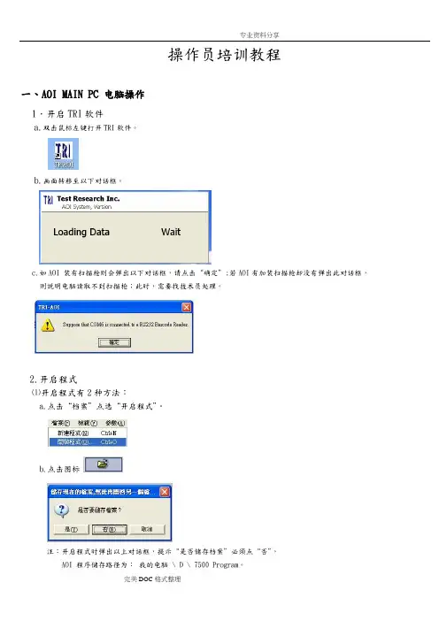
操作员培训教程一、AOI MAIN PC 电脑操作1.开启TRI软件a.双击鼠标左键打开TRI软件。
b.画面转移至以下对话框。
c.如AOI 装有扫描枪则会弹出以下对话框,请点击“确定”;若AOI有加装扫描枪却没有弹出此对话框,则说明电脑读取不到扫描枪;此时,需要找技术员处理。
2.开启程式⑴开启程式有2种方法:a.点击“档案”点选“开启程式”。
b.点击图标注:开启程式时弹出以上对话框,提示“是否储存档案”必须点“否”,AOI 程序储存路径为:我的电脑 \ D \ 7500 Program。
⑵点选所需程式a.开启程式后弹出以下对话框提示“是否自动设定板宽”如需调整轨道宽度点击“是”,反之点击“否”。
b.随之将会弹出以下对话框提示“是否更改Support Pin设定值”请点击“否”。
⑶测试前设定检查a.检查是否连接维修站;检查“参数-使用者模式-连接维修站”是否画“√”。
b.检查测试模式点选“操作-全自动模式”⑷点测试按钮开始测试二、PLC人机界面操1.板宽调整a.用手指点击PLC左、右下角的两个隐藏键b. 点选“其他设定”c.点选“板宽”d.选择“手动调整”e.出现以下界面后开始调整板宽f.扭转设备轨道摇杆调整轨道宽度g.轨道调整OK后点击“返回”h.点击“复归”i.点击“复归”后提示“确定?”,点击“是”,设备开始复归。
j.复归完成后回到待机界面点击“连续测试”三、Repair电脑操作1.开启Repair 软件a.双击鼠标左键打开Ptril 软件。
b.软件开启后弹出以下对话框,点击“OK ”c.双击“MAIN PROG ”进入Repair station(维修站)不良品认识R,C元件的不良缺件空焊移位少锡立碑IC类型元件的不良翘脚少锡错方向短路。

目录1培训手册介绍—-————---—-—-———————--------—--———-—--——---——22系统安全与环境保护-—--——-—-———-———--—--——-——-————--—--————-----33机器人综述-—----—---——--—--—----—-—-—-——-———-——-——-—-—-54机器人示教——--——--—-—-----—--—---—-—---——-—--———--——-—125机器人启动-—-——--—-——--——-—-—-—----—--—-——--——-----———256自动生产-—————---—-——--—--—————-——-———-—-—-——----———277 编程与测试---—--—--—----—--——-—-—---——-—-——-—-————--——328 输入输出信号--—-—---——-—----—---—--—-——-—---—-—-——-—-—-—509 系统备份与冷启动—--—--——-—--—--——--—-—-—---—-—--——-—————-———5210 文件管理---—-—-——--—--——-———-—--—————-———-——--——--—-54第一章培训手册介绍•本手册主要介绍了A B B机器人的基本操作与运行。
•为了理解本手册内容,不要求具有任何机器人现场操作经验。
•本手册共分为十章,各章节分别描述一个特别的工作任务和实现的方法。
•各章节之间有一定联系。
因此应该按他们在书中的顺序阅读。
•借助本手册学习操作机器人是我们的目的,但是仅仅阅读此手册也应该能帮助你理解机器人的基本的操作。
•本手册依照机器人标准的安装编写,实际操作根据系统的配置会有差异.•本手册仅仅描述实现通常的工作作业的某一种方法,如果你是经验丰富的用户,可能会有其他的方法。
•其他的方法和更详细的信息请阅读下列机器人手册(英语版).《使用指南U s e r’s G u i d e》与《产品手册P r o d u c t M a n u a l》。

Alcatel-OXE培训手册目录一.硬件介绍 (2)1.ACT-28机架介绍 (2)2.电源接口 (2)3.电路板介绍 (4)(1)CPU板 (4)(2) eZ32板 (4)(3)eUA32板 (4)(4)NPRAE电路板 (5)(5)GPA2电路板 (5)(6)INTOF2板 (6)(7)INTIP2板 (6)4.电路板插拔方法 (7)二.软件 (8)1. 创建分机(登录交换机用户名密码都是mtcl) (8)2. 修改分机的公网类别(内线、市话、国内长途、国际长途) (9)3. 删除分机 (11)4. 查看话务台的工作状态 (12)5. 查看中继的工作状态 (13)(1). 实时查看中继线状态 (13)(2). 静态查看中继线状态 (13)6. 查看电路板的工作状态 (13)(1). 查看所有电路板状态 (13)(2). 查看某个电路板状态 (14)7. 查看话机的工作状态 (14)8. 查看模拟/数字用户板的各端口占用状况 (15)9. 修改数据后如何进行数据备份 (16)三.分机功能 (17)一.硬件介绍1.ACT-28机架介绍信息中心Alcatel-OXE配置两个ACT28(12U)机架,下面为主机架,上面为扩展机架。
CPU板在主机架中,必须插在6槽位或20槽位。
CPU卡可独立设置耦合IO2N卡(可选)。
在扩展ACT28中,INTOF链路卡插在CPU槽位。
2.电源接口Alcatel-OXE供电采用-48V直流供电,电源模块如下:说明:B:蓝色 +48V电缆 R:红色 -48V电缆 Y:黄色接地电缆3.电路板介绍(1)CPU板CPU7-2处理单元是系统的核心部分,它可以处理系统应用程序(电话应用程序、信息通信处理应用程序、语音邮件应用程序等)。
接口:2.5英寸IDE硬盘驱动S ATA硬盘驱动U SB连接以太网连接软件保护C OM端口L ED指示灯:CPU板上有2个指示灯,分别是“CPU”灯和“ETH”灯。


操作手册目录第一章VLAN划分与路由功能设置第二章FRNT环网与链路聚合功能设置第三章Lynx+ 与Redfox 恢复出厂设置第四章3G路由器通信设置第一章 VLAN 划分与路由功能设置一、 样机1、L210-F2G2、L110-F2G3、开关电源4、以太网设备终端5、其他(线缆等)二、 现场应用一(VLAN 划分与OSPF 应用)以上拓扑图说明:由于现场设备数量若干,处于的网段可能不同,且需要相互之间进行通信,此时需要进行VLAN 划分,及跨网段的数据交换(路由功能)。
L210-F2G (适用功能 VLAN+OSPF ) L110-F2G (适用功能 VLAN )本手册根据如上拓扑图进行操作步骤指导,实现PC机(192.168.0.100)能够访问到终端设备A、B、C等。
默认情况下,交换机的出厂IP地址为:192.168.2.200子网掩码:255.255.255.0用户名: admin密码: westermo三、操作步骤1、根据上面的拓扑图先设置上位PC的IP地址192.168.2.100 (保证与交换机先通信上,并根据实际需求更改交换机的配置信息)。
2、通过浏览器登录 192.168.2.200(默认此处为新交换机)进入交换机查看与配置页面,见下图:3、通过Status可查看相关交换机信息,如下图所示:默认密码:westermo4、通过Configuration ,可进行相关功能配置,如下图所示:步骤:Configuration →network →interface →更改当前上位PC 与交换机相连端口的IP 地址(注:此处相连的端口应按照之前规划好的进行连接,便于后面设置)。
5、通过Configuration ,修改交换机IP 地址,如下图所示:修改为:192.168.0.250, 并单击 Apply.5、修改完毕后,由于PC机与交换机的新地址存在冲突,故此时修改上位PC地址,见下图:6、通过浏览器重新登录交换机192.168.0.250,并进行VLAN划分设置,具体见下图:步骤:Configuration→VLAN→VLANs 进行VLAN及端口划分(注:Tagged表示交换机之间或交换机与上位之间的对接设置;Untagged表示交换机与终端设备的接口设置。


Penny & GilesOmni Plus ModuleBasic Operation InstructionsOmni Plus Basic Operation Manual3TABLE OF CONTENTSINTRODUCTION (4)Omni Plus Module (4)DRIVE SELECTION (6)Operation (6)ACTUATOR SELECTION (7)Operation (7)AUXILIARY CONTROL MODULE (ACM) SELECTION (8)Operation (8)4Basic Operation Manual Omni Plus INTRODUCTIONWelcome to Quantum Rehab, a Division of Pride Mobility Products Corporation. Quantum Rehab is dedicated to the customization of power chairs for users with advanced rehabilitation and mobility issues. Quantum Rehab also expands possibilities for enhanced healthcare attendant control over power chair functions to provide a secondary level of support for our customers where necessary.Penny & Giles Omni Plus ModuleThe Omni Plus Module is a universal specialty controls interface which accepts signals from a variety of input devices such as finger steering controls, head arrays, Sip-N-Puff systems, and lap trays. The Omni Plus then translates the input signals into user functions compatible with the power chair control system. The purpose of the Omni Plus is to enhance and expand input device function, so that the user can do more with their power chair.This manual is designed to explain basic operation for the following functions available with the Omni Plus:1.Drive Selection- The user controls the speed level and direction of the power chair using the Omni Plus and the input device. The user can choose one of five different speed levels.2.Actuator Selection- The user controls the various seat functions available with their power chair using the input device and the Omni Plus.NOTE: Actuator selection is dependent on the type of seat installed on the power base.3.Auxiliary Control Module (ACM) Selection- The user controls up to two ACM channels using the input device and the Omni Plus.Figure 1 provides information on the Omni Plus components and connections. Use this diagram to familiarize yourself with the function and location of each component before using the Omni Plus Module.Omni Plus Basic Operation Manual5Figure 1. Omni Plus Components and Connections6Basic Operation Manual Omni PlusDRIVE SELECTIONThe drive speeds range from drive speed 1, configured as the slowest speed,to drive speed 5, configured as the fastest speed. Each drive speed setting increases a percentage of the overall base speed.Figure 2. Power-up DisplayFigure 3. Standby Mode Display OperationTo operate the drivefunction, power up the system using the On/Off Button on/off input on the bottom of NOTE: After the initial display figure 2 is shown, the display change to the Standby Mode in figure 3. This display will change in appearance depending oninput device used.the input device, the Omni the input device will operate power base at the displayed speed.drive speed, press the Mode Button or activate the external mode switchthat is plugged into the mode/stop input on the bottom of the Omni Plus. See figure 1. When SPEED 1 on the Omni Plus display flashes, a right command on the input device will increase the speed to 2. If the display flashes when in SPEED 2, a left command on the input device will decrease the speed to 1.These right and left commands will increase or decrease the drive speed while in drive selection mode.Omni Plus Basic Operation Manual7Figure 5. Actuators/Exit DisplayACTUATOR SELECTIONtilt, power leg rests (left, right, these actuators.OperationTo operate the actuator menu option. Press the Mode into the mode/stop input (see figureFigure 4. Actuator/Drive Menu 1) twice. Apply a forward (up) command or a reverse (down) command to the input device to select between Actuators, Drive and ACM. Use the Select Button or a right command to choose ACTUATORS, then press the Mode Button . The screen will display as shown in figure 4.Press the Select Button , or give a right command to the input device to toggle among the actuator functions. A forward command or a reverse command to the input device will activate the selected function, and adjust the seat. To exit, scroll right or left until the screen display reads EXIT, and then give a forward command or press the Mode Button . See figure 5.NOTE: The system can programmed so that forward reverse commands select function and right and commands lower and raise authorized provider for information on this feature.8Basic Operation Manual Omni PlusAUXILIARY CONTROL MODULE (ACM) SELECTIONAn ACM is used to interface with devices outside of the power chair s control system, including environmental controls and computers.NOTE: Not all power chairs are equipped with this function. Contact your authorized provider for more information on ACM functioning.The Omni Plus can support up to two ACM channels on a properly equipped power chair, and the settings for the available channels are 0, 1, and 2.0 no ACM channel is supported by the Omni Plus, and no options are available.1 one channel is supported by the Omni Plus, allowing one available option.2 two channels are supported by the Omni Plus, allowing two available options.OperationApply a forward (up) command or a reverse (down) command to the input device to select between Actuators, Drive and ACM. Use the Select Button to choose between ACM setting 1 or 2. Once a setting is selected, the display will read as in figure 6.NOTE: ACM channel 1 or channel 2 control is dependant on Omni Plus operation configuration, which includes momentary, latched, or communications.Figure 6. ACM Channel DisplayMomentary ConfigurationACM control in the momentary operation configuration is acheived through directional commands. A forward command will operate the forward output on the ACM channel.Likewise, a reverse command will operate the reverse output, a left command will operate the left output, and a right command will operate the right output.Omni Plus Basic Operation Manual9 NOTE: No outputs will be operational when the input device is in the neutral position.Latched ConfigurationACM control in latched operation configuration is also acheived through directional commands. The difference from momentary configuration is that the output will remain active after the input device is released. In order to cancel the command to the output, another command must be given. A forward command will operate the forward output. This command can only be cancelled by a reverse, left, or right command to the input device. Communications ConfigurationACM control in communications operation configuration allows for operation of two outputs at the same time. A simultaneous forward and left command will operate both the forward and left outputs. Similarly, a simultaneous reverse and right command will operate both the reverse and right outputs. As with momentary configuration, no outputs will be operational when the input device is in the neutral position.10Basic Operation Manual Omni PlusNOTESOmni Plus Basic Operation Manual11NOTES。

欧宝雅特ASTRA-H GTC 技术培训手册ASTRA GTC新技术特征&PEPS系统本手册内容属于内部培训教材,禁止外泄。
其中内容和实际车型部分存在一定差距,不能作为实际维修的依据。
Astra-H GTC 示概述第一部分Astra-H GTC 开锁和起动系统第二部分Astra-H GTC 系统框架和线路图第三部分第一部分:Astra-H GTC 概述我们在下列章节及“所有车型”一章中,对2005.5 年型Astra-H GTC的技术改进和新性能,进行了详细描述。
●第一部分Astra-H GTC概述1.................................................................... .. (1)1●类型和车型代码-Astra-HGTC ................................................................. . (3)●车辆识别码(VIN )-Astra-HGTC ................................................................. (4)●尺寸和容量-Astra-H (5)●顶升点-Astra-H GTC ................................................................. .. (6)●维修:................................................................. ..................................................................... . (6)●经济备件-Astra-H GTC ................................................................. . (7)●维修:................................................................. ..................................................................... . (8)●维..................................................................... .. (10)●维修:................................................................. ..................................................................... .. (11)●前拖车环-Astra-H GTC ................................................................. .. (16)●顶升点-Astra-H GTC ................................................................. (17)●维修:................................................................. ..................................................................... .. (17)●检查装配公差-Astra-H GTC ................................................................. (18)●后拖车环-Astra-H GTC ................................................................. .. (20)●前面板-Astra-H GTC ................................................................. (21)●维修:................................................................. ..................................................................... .. (21)●后面板-Astra-H GTC ................................................................. (22)●维修:................................................................. ..................................................................... .. (22)●背门-Astra-H GTC ................................................................. ..................................................................... .23●维修:................................................................. ..................................................................... .. (23)●识别牌上的涂装数据/颜色范围-Astra-H GTC ................................................................. . (24)●标配涂装塑料件概述-Astra-H GTC ................................................................. (25)●维修:................................................................. ..................................................................... .. (25)●维修:................................................................. ..................................................................... .. (26)●去除后窗玻璃嵌条-Astra-H estate .............................................................. (27)●标准运动型悬架-Astra-H GTC ................................................................. .. (27)●可供选择的发动机变形型式-Astra-H GTC ................................................................. (28)●Introduction of the Z 13 DTH DOHC engine -Astra-H GTC ................................................................. (29)●CP1H高压油泵-Astra-H GTC ................................................................. . (30)●Z 13 DTH发动机的扭矩和功率曲线-Astra-H GTC ................................................................. (31)●VNT涡轮增压器-Astra-H GTC ................................................................. .. (32)●Z 13 DTH 中间轴支架-Astra-H GTC.................................................................. .. (34)●CRIP2-MI喷油器-Astra-H GTC ................................................................. (35)●维修:................................................................. ..................................................................... .. (36)● M20-6 六速手动变速器配Z 13 DTH柴油发动机-Astra-H GTC (37)●调整M20-6/M32-6 变速器油液液位-Astra-H............................................................. .. (39)●维修:................................................................. ..................................................................... .. (39)●维修:................................................................. ..................................................................... (39)第二部分 Astra GTC 开锁和起动系统●开锁和起动系统................................................................... ..................................................................... ..40●开锁与起动系统................................................................... ..................................................................... ..41●开锁与起动系统................................................................... .. (42)1●开锁与起动系统的工作原理................................................................... (44)●接收器/发射器装置................................................................... (44)●客舱天线的位置46●车外天线的位置................................................................... .. (47)●O&S控制单元................................................................... .....................................................................47●CIM ...................................................................................................................................... (48)●ESCL ................................................................ ..................................................................... .. (48)●UID ................................................................. ..................................................................... . (48)●UID 的电源................................................................... ..................................................................... .. (49)●UID 的功能................................................................... ..................................................................... .. (49)●UID 中的应急钥匙................................................................... .. (50)●应急起动................................................................... ..................................................................... .. (50)●更换UID 电池................................................................... ..................................................................... .51●车门把手锁闭传感器................................................................... (53)●车门把手-独立部件................................................................... (53)●汽车门锁伺服电机................................................................... . (54)●被动进入程序................................................................... .....................................................................56●汽车车门的开锁................................................................... .. (56)●选项二:................................................................. ..................................................................... . (56)●被动起动/停机程序................................................................... (56)●被动离车程序................................................................... .....................................................................58●开锁与起动-显示和信息................................................................... . (58)●“开锁与起动”简明指南................................................................... . (59)● 1 )系统部件................................................................... ..................................................................... ..59● 2 )汽车开锁:................................................................. .....................................................................● 3 )操作汽车(起动和停机):................................................................ .. (60)● 4 )汽车上锁................................................................... ..................................................................... ..60● 5 )组合仪表上的控制指示灯................................................................... . (61)● 6 )应急系统操作:................................................................. . (61)第三部分 Astra GTC 系统框架线路图Immobiliser Open & Start ―block (阻动系统框架图)Switch (起动开关)67open start 1 (开锁起动系统) -1 68open start 2 (开锁起动系统 -2 71open start 3 (开锁起动系统) 3 73open start central door locking 1 (中控门锁系统) 1 75open start central door lock 2 (中控门锁系统) 2 78ATWU-Anti theft warning system (防盗警报系统)81Rec (后部电器模块)88can bus high block (高速网络框架图)105Can bus high circult (高速网络线路图)108can bus low block (低速网络框架图)113DLC LINK (数据线连接)115Instrument 1 (仪表 1 )118Instrument 2 (仪表 2 )1212类型和车型代码-Astra-H GTCAstra-H GTC 的车身设计有左、右侧驾驶型可供选择。

Safety Instructions ManualOperator and Super visor InformationThis is one of four manuals supplied with your machine. • Installation Manual • Safety Instructions Manual • Operations Manual • Maintenance ManualREAD ALL MANUALS BEFORE OPERATING MACHINERY. Operating machinery before reading and understanding the contents of all four manuals greatly increases the risk of injury.Each of the four machine manuals describe ‘best practices’ in handling, installing, operating and maintaining your machine. The contents of each manual is subject to change without notice due to improvements in the machinery or changes in National or International standards. All rights reserved. Reproduction of this manual in any form, in whole or in part, is not permitted without the written consent of Edwards Manu-facturing Company.Keep all manuals close to the machine to allow for easy reference when necessary.Provide operators with sufficient training and education in the basic functions of the machine prior to machine operation.Do not allow for operation of the machine by unqualified personnel. Ed-wards Manufacturing Company is not liable for accidents arising from unskilled, untrained operation.Do not modify or change the machine without written authorization from Edwards Manufacturing Company. Unauthorized modification to a ma-chine may result in serious operator injury, machine damage and will void your machine warranty.Never leave a powered machine unattended. Turn machinery OFF be-fore walking away.This machine is manufactured for use by able bodied and able minded operators only. Never operate machinery when tired or under the influ-ence of drugs or alcohol.Do not resell, relocate or export to a destination other than to the original point of sale. Edwards has designed this machine to meet the stan-dards of the original receiving country and is not liable for meeting any governing body or performance standards beyond those of the original receiving country.Signal Word DefinitionIndicates a hazardous situation that, if not avoided,will result in death or serious injury.Indicates a hazardous situation that, if not avoided,could result in death or serious injury.Indicates a hazardous situation that, if not avoided,could result in mild or moderate injury.Indicates information considered important, but nothazard related.Signal Word P anel on MachineCritical machine safety information is identified on signal word labels. Labels are attached adjacent to the potentially hazardous locations of the machine. Reference the Safety Instruction Manual for additional informa-tion regarding the potentially hazardous condition identified on the label. Review ALL labels on the machinery, reference the operational pre-cautions and safe operations sections within this manual before any operation activity is initiated.Failure to read and understand the signal word labels affixed to the machinery may result in operator death or injury.1 GeneralOperator and Supervisor Information Signal Word DefinitionSignal Word Panel2 Signal Word Panel - Machine Front3 Signal Word Panel - Machine Back4 Signal Word Panel - Machine Right5 Signal Word Panel - Machine Left6 Signal WordsDanger Panel Warning Panel Notice PanelAdditional Graphic InformationSafety ManualTable of ContentsIRONWORKER.Optional Hydraulic Accesory PackDanger Panel Warning PanelElectrical HazardThis is the electrical hazard symbol. It indicates there are dangerous high volt-ages present inside the enclosure of this product. ONLY qualified, authorized, main-tenance, service or Certified Electricians should gain access to electrical panel. Do not operate this equipment from any power source that does not match the voltage rating stamped on the equipment. Refer to the Manufacturer’s Identification Label for operational requirements.Lockout PowerDanger circuits are live. Lockout/Tagout the upstream power source. Lockout/Tagout machinery according to Employer proce-dures.Voltage (Varies by consumer requirement)Indication of operating power requirements. This product should be operated only from the type of source indicated on the manu-facturer’s identification label Installation should be in compliance with applicable sections of the National Electric Code. Consult your local building code before installing.Phase (Varies by consumer requirement)Indication of electrical phase requirements. This product should be operated only from the type of source indicated on the manu-facturer’s identification label Installation should be in compliance with applicable sections of the National Electric Code. Consult your local building code before installing.Horsepower (Varies by model)Indication of horsepower requirements. This product should be operated only from the type of source indicated on the manufactur-er’s identification label Installation should be in compliance with applicable sections of the National Electric Code. Consult your local building code before installing. Hertz (Varies by consumer requirement)Indication of electrical cycles per second. This product should be operated only from the type of source indicated on the manu-facturer’s identification label Installation should be in compliance with applicable sections of the National Electric Code. Shear/Crush HazardMoving parts can cut and crush. Keephands clear while operating. Lockoutpower before servicing. Immediatelyreplace guards after adjustment, repair orservice.Wear Personal ProtectiveEquipmentTo avoid physical hazard, always wear per-sonal protective equipment. Wear protec-tive eyewear, clothing, gloves, footwear,head-gear and hearing protection whileoperating or servicing this machinery.Fluid Injection HazardHydraulic hoses and cylinders are underpressure. Pressurized fluid can pierce skinand cause severe injury. To avoid physicalhazard, always wear personal protectiveequipment. Keep hands clear while oper-ating. Lockout power before servicing.Immediately replace guards after adjust-ment, repair or service.Do Not Operate With GuardRemovedPhysical barriers and guards have beendesigned and installed to protect the oper-ator from moving parts that can pinch, cutand crush. Keep hands clear while oper-ating. Lockout power before servicing.Immediately replace guards after adjust-ment, repair or service to moving parts.Notice PanelIronworker OperationThis manual outlines the basic functionsassociated with typical Ironworker opera-tions and is neither intended to create acomprehensive list of, nor describe everyoperation possible with an Ironworkertool. Ironworker machines are designed topunch, shear and notch mild steel (A36)plate, barstock and angle. A wide range ofaccessories are available to fabricate rod,square stock, sheet metal and pipe. DO NOTUSE THIS EQUIPMENT FOR ANY PURPOSENOT DESCRIBED IN THE MANUALS.Ironworker machines are angerousand require extreme care and cautionin the safe installation, operation andmaintenance of the machinery. EdwardsManufacturing Company strongly sug-gests read ing and und erstand ing allmanuals associated with the machineryas well as obtaining certified, techni-cal, in ustrial machinery operationsand maintenance training to reduce therisk of injury. Regardless of the contentsof the machinery manuals Ed ward sManufacturing Company will not be heldliable for accid ents caused by lack oftraining.Wear Personal ProtectiveEquipmentTo avoid physical hazard, always wear per-sonal protective equipment. Wear protec-tive eyewear, clothing, gloves, footwear,head-gear and hearing protection whileoperating or servicing this machinery.Forklift LocationThis machine is equiped with rated fork-lift movement points. Do not attempt tolift the machinery by any other means.Inappropriate movement of the machin-ery may result in serious operator injury,machine damage and will void machinewarranty. Consult the installation manualfor equipment weight ratings. Providerated forklift and certified forklift operatorto move machinery to appropriate location.Refer to Manuals:Safety, Installation, Operationsand MaintenanceManuals contain critical instructionsregarding proper procedures for yourmachinery. Understand the contents of allmanuals thoroughly. Failure to follow properprocedures may result in serious operatorinjury, machine damage and will void yourmachine warranty. Keep manuals close tothe machine for easy reference.Heat HazardTo avoid physical burn hazard, alwayswear personal protective equipment. Wearprotective clothing and gloves while work-ing adjacent to or on the affected surface.Safety GroundSafety earth ground location.Do Not Use Non-ApprovedLubricantsThis machine requires lubrication ofmoving mechanical parts (grease) and themaintenance of hydraulic fluids. Consultmaintenance manual for specific lubricationrequirements and application or mainte-nance schedules.PE‘Protective earth’, electrical groundinglocation.Additional GraphicInformationElectric Motor Rotation (Above)Identification of proper electrical motorrotation.Conformité EuropéenneConformity with all legal requirements per-taining to the equipment with the EuropeanEconomic Area.HydraulicsHydraulic fluids must be recycled asrequired by local environmental law. Do notAdditional GraphicInformationElectronicsElectronic equipment must be recycled asrequired by local environmental law. Do notdispose of by adding to the municipal wastestream.MetalMetal components must be recycled asrequired by local environmental law. Do notdispose of by adding to the municipal wastestream.P.O. Box 1。
将ITRAINERMINI 滑到夹子上,打开魔術貼電線紮帶。
保持杆垂直,快速的夹到一边轴的控制下,不要扭轴上的夹子,否则会损坏聚合物控制。
移除设备时,请打开皮带,从轴的控制端将夹子拉开。
安装程序如果您有苹果设备,请到app商店免费下载I trainer golf.下面的设置可在上面找到。
如果您是安卓系统,请到Google play shop店免费下载I trainer golf.它必须用安卓系统2.3.3以上的版本我们的官网上有最新的itrainergolf app的使用手册。
如何使用苹果系统打开您的itrainermini设备,及苹果设备,打开蓝牙,您将看到系统搜索到itrainermini设备,选择并进行连接。
如果您使用多台itrainermini设备,选择在列表中装备的最后3位数编号。
一旦显示连接itrainermini设备,itrainergolf将会自动连接上。
捕捉挥杆1-iphone ipad主菜单几秒后出现,将显示连接上蓝牙状态,选择expertmode 然后滑向左选择一个球杆并点击球杆图像。
捕捉挥杆2-iphone ipad在球后进行设置,并将正面对准目标线,将杆提到水平位置把杆稳在水平位置,确保杆面垂直。
直到你听到提示音瞄准球,稳住杆直到两个指示灯停止闪烁,挥杆。
捕捉挥杆3-iphone ipad当设备探测到你在位置上并准备好挥杆时,你将在屏幕上看到指示并听到哔的一声一旦挥杆完成,他将自动上传结果,仪表盘上可看到数据。
要想了解更多可以将屏幕滑向左。
点击3D按钮可以看3d 图像。
如果要捕捉挥杆,回到仪表盘再次选择挥杆。
如果要捕捉多次,点击MENU 选择AUTO (自动)如何使用安卓系统第一次使用安卓系统连接itrainermini设备时,需要进行配对。
打开itrainermini设备,同时打开安卓系统,打开蓝牙,选择搜索设备,找到itrainermini设备,选择并进行连接。
一旦显示连接itrainermini设备,以后会自动连接上,无需每次都连接,除非你要删除配对或者替代别的设备。
目录第一部分 操作与维护一、概述 (41)二、机床操作 (44)1.数控机床的操作顺序总概 (44)2.操作面板介绍 (45)3.基本操作 (59)4.手动运行操作方式 (59)5.MDI运行操作方式 (62)6.自动运行操作方式 (63)7.程序操作 (70)8.参数设置 (75)9.刀库操作 (79)10.辅助操作 (80)三、机床的电气维护 (82)1.机床电气的日常维护 (82)2.故障状态下的机床电气维护 (82)3.数控机床采用OSP7000M/700M的基本配置与资料介绍 (82)4.故障分类与诊断方法 (83)第二部分 数控编程第一章 概述 (87)一、基本知识 (87)二、数控编程的内容 (87)1.手工编程的一般步骤 (87)2.自动编程 (90)第二章 擞控机床的编程基础 (91)一、坐标系设定和坐标轴的确定方法 (51)1.基本坐标系及其方向 (91)2.几种典型数控机床坐标轴的判定及说明 (92)3.机床坐标系与工件坐标系 (92)二、OKUMA系统常用编程代码简介 (94)1.准备功能G代码 (94)2.辅助功能M代码 (95)3.其它辅助代码(F、S、T等) (96)4.与几种常用数控系统NC代码的对照比较 (97)第三章 基本的编程方法 (98)一、几个基本概念 (98)1.尺寸设定单位 (98)2.绝对坐标和增量坐标 (98)3.进给速度指定 (98)二、数控加工程序的结构及格式 (98)1.程序的组成 (98)(1)程序名与文件名 (99)(2)顺序号 (100)2.程序段格式 (100)3.主程序与子程序 (100)三、部分功能详述 (101)1.工件坐标系的选择 (101)2.工件坐标系的变更 (102)3.工件坐标系的平移和旋转 (102)4.快速定位与直线插补 (103)5.圆弧插补 (104)6.刀具长度补偿 (105)7.刀具半径补偿 (105)8.固定循环 (106)9.可编程镜像加工 (110)10.公共变量与IF语句 (110)第四章 编程实例 (112)一、实例1 (112)1.常用编程指令 (112)2.工作精度内容 (112)3.定位精度说明 (113)4.NC程序及中文注释 (113)(1)精切圆 (113)(2)精切斜方 (114)(3)精镗孔距 (116)(4)测试X方向定位精度 (118)(5)测试Y方向定位精度 (119)(6)测试Z方向定位精度 (120)二、实例2 (121)数控铣床讲义第一部分操作与维护编制:王孙安周嵘2002年3月一、概述OSP7000M/700M是日本OKUMA公司专门为铣床配置的数控系统,具备强大的功能,并且可靠稳定,是当今最成熟的数控系统之一。
S4C IRB 基本操作培训教材目录1、培训教材介绍2、机器人系统安全及环境保护3、机器人综述4、机器人启动5、用窗口进行工作6、手动操作机器人7、机器人自动生产8、编程与测试9、输入与输出10、系统备份与冷启动11、机器人养护检查表附录 1 、机器人安全控制链附录 2 、定义工具中心点附录 3 、文件管理1 、培训教材介绍本教材解说 ABB 机器人的基本操作、运转。
你为了理解其内容不需要任何先前的机器人经验。
本教材被分为十一章,各章分别描绘一个特其余工作任务和实现的方法。
各章相互间有必定联系。
所以应当按他们在书中的次序阅读。
借助此教材学习操作操作机器人是我们的目的,可是只是阅读此教材也应当能帮助你理解机器人的基本的操作。
此教材依据标准的安装而写,详细依据系统的配置会有差别。
机器人的控制柜有两种型号。
一种小,一种大。
本教材采纳小型号的控制柜表示。
大的控制柜的柜橱有和大的一个相同的操作面板,可是位于另一个地点。
请注意这教材只是描绘实现往常的工作作业的某一种方法,假如你是经验丰富的用户,能够有其余的方法。
其余的方法和更详尽的信息看以下手册。
《使用指南》供给所有自动操控功能的描绘并详尽描绘程序设计语言。
此手册是操作员和程序编制员的参照手册。
《产品手册》供给安装、机器人故障定位等方面的信息。
假如你仅希望能运转程序,手动操作机器人、由软盘调入程序等,不用要读 8-11 章。
2 、机器人系统安全及环境保护机器人系统复杂并且危险性大,在训练时期里,或许任何别的操作过程都一定注意安全。
不论任何时间进入机器人四周的保护的空间都可能致使严重的损害。
只有经过培训认证的人员才可以进入该地区。
请严格注意。
以下的安全守则一定恪守。
万一发生火灾,请使用二氧化碳灭火器。
急停开关( E-Stop )不一样意被短接。
机器人处于自动模式时,不一样意进入其运动所及的地区。
在任何状况下,不要使用原始盘,用复制盘。
搬运时,机器停止,机器人不该置物,应空机。