输入输出-说明书
- 格式:ppt
- 大小:375.50 KB
- 文档页数:15
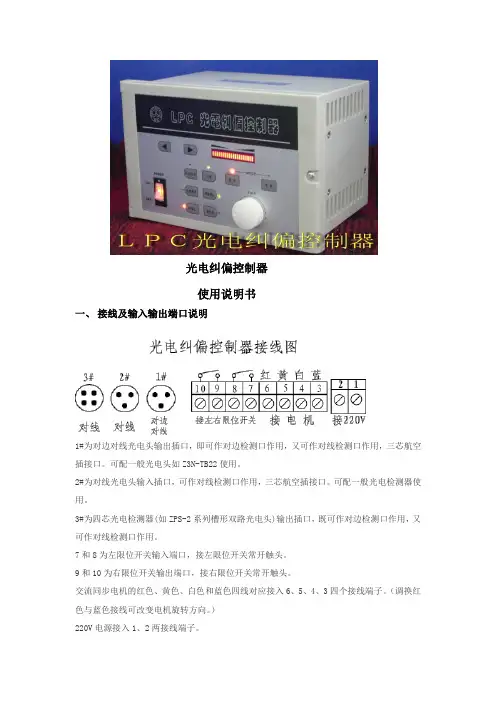
光电纠偏控制器使用说明书一、接线及输入输出端口说明1#为对边对线光电头输出插口,即可作对边检测口作用,又可作对线检测口作用,三芯航空插接口。
可配一般光电头如Z3N-TB22使用。
2#为对线光电头输入插口,可作对线检测口作用,三芯航空插接口。
可配一般光电检测器使用。
3#为四芯光电检测器(如ZPS-2系列槽形双路光电头)输出插口,既可作对边检测口作用,又可作对线检测口作用。
7和8为左限位开关输入端口,接左限位开关常开触头。
9和10为右限位开关输出端口,接右限位开关常开触头。
交流同步电机的红色、黄色、白色和蓝色四线对应接入6、5、4、3四个接线端子。
(调换红色与蓝色接线可改变电机旋转方向。
)220V电源接入1、2两接线端子。
二、运行前的准备工作1、接线:按接线图要求将电源,电机,限位开关,光电头对应接好。
2、电机方向极性确定:(如按手动键,使控制器处于手动状态,再按极性正键),则按键,电机正方向旋转,材料活动架往左移动,按键,电机反方向旋转,材料活动架往右移动,如电机旋转方向与实际相反,可将电机红蓝两线调换接线.3、限位开关控制电机停止方向确定:(如按手动键,使控制器处于手动状态,再按极性正键), 则按键,电机正方向旋转,后碰触活动架移动方向的限位开关,电机运转停止,则表示限位有效,反之则碰触一端限位开关,电机应运转停止,则表示限位开关接线相反,必须给予调换.注意:检验限位开关时必须在电机运转的有效行程内,必须在手动档检验,否则一但限位失灵将损坏电机丝杆的机械结构。
4、材料对边或对线选择:对于材料首先确定它的基准位置是材料边缘还是印刷线条。
确定跟踪边缘以后,再确定左边缘还是右边缘,以后再决定电机方向极性。
对于印刷品的线条一般定于2MM以上线条作为对边处理。
反之则作为对线处理。
5、光电头的定位、调整:按自动键、对边对线键,确定是跟踪材料边缘或印刷线条后,将光斑对准材料边缘或印刷线条,调整光电头位置观察光电头上的指示灯,指示灯从亮-暗-亮,则表示设定成功,若无该状态,则无基准工作。
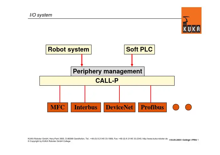
I 03.09.2003 I College I PRhI 1KUKA Roboter GmbH, Hery-Park 3000, D-86368 Gersthofen, Tel.: +49 (0) 8 21/45 33-1906, Fax: +49 (0) 8 21/45 33-2340, http://www.kuka-roboter.deI/O systemCALL-PMFC DeviceNet Interbus Periphery managementSoft PLCRobot system ProfibusI 03.09.2003 I College I PRhI 2KUKA Roboter GmbH, Hery-Park 3000, D-86368 Gersthofen, Tel.: +49 (0) 8 21/45 33-1906, Fax: +49 (0) 8 21/45 33-2340, http://www.kuka-roboter.deStructure of IOSYS.INI[CONFIG]VERSION=1.00[DRIVERS];MFC=0,mfcEntry,mfcdrv.oINTERBUS=1,ibusInit,ibusdrv.o;INTERBUSPCI =15,ibsCPPciInit,ibpcidrv.o [MFC]; I/O assignments of the MFC [INTERBUS]; I/O assignments of InterbusIOSYS.INIOnly for ISA cardsOnly for PCI cardsI 03.09.2003 I College I PRhI 3KUKA Roboter GmbH, Hery-Park 3000, D-86368 Gersthofen, Tel.: +49 (0) 8 21/45 33-1906, Fax: +49 (0) 8 21/45 33-2340, http://www.kuka-roboter.de[CONFIG]VERSION=1.00[DRIVERS];MFC=0,mfcEntry,mfcdrv.oINTERBUS=1,ibusInit,ibusdrv.o[MFC]; I/O assignments of the MFC[INTERBUS]; I/O assignments of Interbus [END SECTION]Interbus section ISAActivateIOSYS.INII 03.09.2003 I College I PRhI 4KUKA Roboter GmbH, Hery-Park 3000, D-86368 Gersthofen, Tel.: +49 (0) 8 21/45 33-1906, Fax: +49 (0) 8 21/45 33-2340, http://www.kuka-roboter.de[CONFIG]VERSION=1.00[DRIVERS];MFC=0,mfcEntry,mfcdrv.oINTERBUSPCI =15,ibsCPPciInit,ibpcidrv.o[MFC]; I/O assignments of the MFC[INTERBUSPCI]; I/O assignments of Interbus [END SECTION]Interbus section PCIActivateIOSYS.INII 03.09.2003 I College I PRhI 5KUKA Roboter GmbH, Hery-Park 3000, D-86368 Gersthofen, Tel.: +49 (0) 8 21/45 33-1906, Fax: +49 (0) 8 21/45 33-2340, http://www.kuka-roboter.de+24V=TRUE, 0V=FALSEOUTPUTS $OUT[1]$OUT[2]$OUT[3]$OUT[4]$OUT[5]...$OUT[1024]INPUTS $IN[1]$IN[2]$IN[3]$IN[4]$IN[5]...$IN[1024]$IN[1025]=TRUE $IN[1026]=FALSEFrom the peripheryTo the peripheryInputs/outputs of the KRC controllerExample:INB2=2,x2OUTW6=32,x1Byte offset,x Multiplier=Interbus sideIN OUTBWDWByte offsetRobot sideI 03.09.2003 I College I PRhI6KUKA Roboter GmbH, Hery-Park 3000, D-86368 Gersthofen, Tel.: +49 (0) 8 21/45 33-1906, Fax: +49 (0) 8 21/45 33-2340, http://www.kuka-roboter.deKUKA Roboter GmbH, Hery-Park 3000, D-86368 Gersthofen, Tel.: +49 (0) 8 21/45 33-1906, Fax: +49 (0) 8 21/45 33-2340, http://www.kuka-roboter.deI 03.09.2003 I College I PRhI7DI DO DIDOIf data from the slave interface are to be accessed,then the offset896or larger must be used on theInterbus side.Example:INB20=896,x8OUTB20=896,x8-An output on the PLC is aninput on the robot.-An input on the PLC is anoutput on the robot.I 03.09.2003 I College I PRhI8KUKA Roboter GmbH, Hery-Park 3000, D-86368 Gersthofen, Tel.: +49 (0) 8 21/45 33-1906, Fax: +49 (0) 8 21/45 33-2340, http://www.kuka-roboter.deI 03.09.2003 I College I PRhI 9KUKA Roboter GmbH, Hery-Park 3000, D-86368 Gersthofen, Tel.: +49 (0) 8 21/45 33-1906, Fax: +49 (0) 8 21/45 33-2340, http://www.kuka-roboter.deANALOG OUTPUTS $ANOUT[1]...$ANOUT[32]ANALOG INPUTS $ANIN[1]...$ANIN[16]From the peripheryTo the peripheryAnalog inputs/outputs of the KRC controllerI 03.09.2003 I College I PRhI 10KUKA Roboter GmbH, Hery-Park 3000, D-86368 Gersthofen, Tel.: +49 (0) 8 21/45 33-1906, Fax: +49 (0) 8 21/45 33-2340, http://www.kuka-roboter.deConfiguration of analog I/Os (1)Type :Justification, sign Byte offset,Exponent 2,Type Interbus side =ANIN ANOUTIndexRobot side Cal factor,CAL factor:Limitation of the value rangeThis entry is optional.For the analog module,the specified value in digits corresponds to the nominal value (e.g. 10V).2 : left,without sign3 :left, with sign0 : right,without sign 1 :right, with signKUKA Roboter GmbH, Hery-Park 3000, D-86368 Gersthofen, Tel.: +49 (0) 8 21/45 33-1906, Fax: +49 (0) 8 21/45 33-2340, http://www.kuka-roboter.deI 03.09.2003 I College I PRhI11I 03.09.2003 I College I PRhI 12KUKA Roboter GmbH, Hery-Park 3000, D-86368 Gersthofen, Tel.: +49 (0) 8 21/45 33-1906, Fax: +49 (0) 8 21/45 33-2340, http://www.kuka-roboter.deANIN1=4,16,3,CAL30000Example:Phoenix IB IL AI 2/SF:IOSYS.INI:From the manual:I 03.09.2003 I College I PRhI 13KUKA Roboter GmbH, Hery-Park 3000, D-86368 Gersthofen, Tel.: +49 (0) 8 21/45 33-1906, Fax: +49 (0) 8 21/45 33-2340, http://www.kuka-roboter.deANOUT1=4,16,2 or ANOUT1=4,16,2,CAL65535Example: Phoenix IB IL AO 1/SF:IOSYS.INI:From the manual:FFFFHex = 65535DecI 03.09.2003 I College I PRhI 14KUKA Roboter GmbH, Hery-Park 3000, D-86368 Gersthofen, Tel.: +49 (0) 8 21/45 33-1906, Fax: +49 (0) 8 21/45 33-2340, http://www.kuka-roboter.deANIN1=4,13,3 or ANIN1=4,13,3,CAL4095Example: Phoenix ST modules:IOSYS.INI :From the manual:Note:7FF8Hex = 1111 1111 1111 1000Bin1111 1111 1111 1Bin = 8191Dec (13 bits)With positive and negative range from –4096 to + 4095Example of a bus configuration•Slave ring:16 DI, 16 DO•Master ring:Bus terminal1:16 DI, 16 DI, 16 DO Bus terminal2: 2 AI, 2 AO, 8 DI Bus terminal3:16 DI, 8 DOSl:16 DISl:16 DOKRCMasterBT16DI16DI16DOBT2AI2AO8DIBT16DI8DOI 03.09.2003 I College I PRhI15KUKA Roboter GmbH, Hery-Park 3000, D-86368 Gersthofen, Tel.: +49 (0) 8 21/45 33-1906, Fax: +49 (0) 8 21/45 33-2340, http://www.kuka-roboter.deI 03.09.2003 I College I PRhI 16KUKA Roboter GmbH, Hery-Park 3000, D-86368 Gersthofen, Tel.: +49 (0) 8 21/45 33-1906, Fax: +49 (0) 8 21/45 33-2340, http://www.kuka-roboter.de[INTERBUSPCI]; Inputs of the master ring INW0=0,x1; $IN[1-16]INB2=2,x2; $IN[17-32]ANIN1=4,16,3,CAL30000; $ANIN[1]ANIN2=6,16,3,CALl30000; $ANIN[2]INB4=8,x1; $IN[33-40]INW5=9,x1; $IN[41-56]; Outputs of the master ring OUTW0=0,x1; $OUT[1-16]ANOUT1=2,16,3,CAL30000; $ANOUT[1]ANOUT2=4,16,3,CAL30000; $ANOUT[2]OUTB2=6,x1; $OUT[17-24]IOSYS.INISl: 16 DI Sl: 16 DOKRC MasterBT16DI 16DI 16DO BT2AI 2AO 8DI BT16DI 8DO 0-12-30-19-1064-72-58I 03.09.2003 I College I PRhI 17KUKA Roboter GmbH, Hery-Park 3000, D-86368 Gersthofen, Tel.: +49 (0) 8 21/45 33-1906, Fax: +49 (0) 8 21/45 33-2340, http://www.kuka-roboter.de[INTERBUSPCI]; Inputs of the master ring INW0=0,x1; $IN[1-16]INB2= ......; Outputs of the master ring OUTW0=0,1; $OUT[1-16]ANOUT1= ......; Inputs of the slave ring INW12=896,x1; $IN[97-112]; Outputs of the slave ring OUTW12=896,x1; $OUT[97-112]IOSYS.INISl: 16 DI Sl: 16 DOKRC MasterBT16DI 16DI 16DO BT2AI 2AO 8DI BT16DI 8DO 0-12-30-19-1064-72-58I 03.09.2003 I College I PRhI 18KUKA Roboter GmbH, Hery-Park 3000, D-86368 Gersthofen, Tel.: +49 (0) 8 21/45 33-1906, Fax: +49 (0) 8 21/45 33-2340, http://www.kuka-roboter.deComplete I/O configuration[INTERBUSPCI]; Inputs of the master ring INW0=0,x1; $IN[1-16]INB2=2,x2; $IN[17-32]ANIN1=4,16,3,CAL30000; $ANIN[1]ANIN2=6,16,3,CAL30000; $ANIN[2]INB4=8,x1; $IN[33-40]INW5=9,x1; $IN[41-56]; Outputs of the master ring OUTW0=0,x1; $OUT[1-16]ANOUT1=2,16,3,CAL30000; $ANOUT[1]ANOUT2=4,16,3,CAL30000; $ANOUT[2]OUTB2=6,x1; $OUT[17-24]; Inputs of the slave ring INW12=896,x1; $IN[97-112]; Outputs of the slave ring OUTW12=896,x1; $OUT[97-112]IOSYS.INISl: 16 DI Sl: 16 DOKRC MasterBT16DI 16DI 16DO BT2AI 2AO 8DI BT16DI 8DO 0-12-30-19-1064-72-58I 03.09.2003 I College I PRhI 19KUKA Roboter GmbH, Hery-Park 3000, D-86368 Gersthofen, Tel.: +49 (0) 8 21/45 33-1906, Fax: +49 (0) 8 21/45 33-2340, http://www.kuka-roboter.deRobot controller -dig.inputs Interbus input memory Interbus sideRobot side-:-:-:-8-76INW55INB44INB33INB221INW00ContentsByte offset169-11DI 108 DI 87AI6254DI3162DI 1160ContentsByte offsetI 03.09.2003 I College I PRhI 20KUKA Roboter GmbH, Hery-Park 3000, D-86368 Gersthofen, Tel.: +49 (0) 8 21/45 33-1906, Fax: +49 (0) 8 21/45 33-2340, http://www.kuka-roboter.deRobot controller -dig.inputs Interbus input memory Interbus sideRobot side-:-:-:-:-:-:13INW1212-:-:-:-:ContentsByte offset------------DI 89716896-:-:-:-:ContentsByte offsetI 03.09.2003 I College I PRhI 21KUKA Roboter GmbH, Hery-Park 3000, D-86368 Gersthofen, Tel.: +49 (0) 8 21/45 33-1906, Fax: +49 (0) 8 21/45 33-2340, http://www.kuka-roboter.deRobot controller –analog inputsInterbus input memory Interbus sideRobot side::ANIN55-ANIN44ANIN33-ANIN22-ANIN11ContentsINDEX169-11DI 108 DI 87AI265AI14DI 3162DI 1160ContentsByte offsetI 03.09.2003 I College I PRhI 22KUKA Roboter GmbH, Hery-Park 3000, D-86368 Gersthofen, Tel.: +49 (0) 8 21/45 33-1906, Fax: +49 (0) 8 21/45 33-2340, http://www.kuka-roboter.deRobot controller -dig.outputs Interbus output memory Interbus sideRobot side13-:OUTW1212-:-:-:-:-4,...-3OUTB221OUT00ContentsByte offset16896-898,...DO 897-:-7,...8DO 65AO4232DO1160ContentsByte offsetI 03.09.2003 I College I PRhI 23KUKA Roboter GmbH, Hery-Park 3000, D-86368 Gersthofen, Tel.: +49 (0) 8 21/45 33-1906, Fax: +49 (0) 8 21/45 33-2340, http://www.kuka-roboter.deRobot controller –analog outputsInterbus output memory Interbus sideRobot side::ANOUT55-ANOUT44ANOUT33-ANOUT22-ANOUT11ContentsINDEX-:-:-:-:-:8DO 65AO243AO12DO 1160ContentsByte offsetI 03.09.2003 I College I PRhI 24KUKA Roboter GmbH, Hery-Park 3000, D-86368 Gersthofen, Tel.: +49 (0) 8 21/45 33-1906, Fax: +49 (0) 8 21/45 33-2340, http://www.kuka-roboter.deIntel formatByte 1Byte 01 WordBit 8value 256(2exp8)In the Motorola format,the bytes within a word are interchanged.Bit 0value 1 (2exp0)Motorola formatByte 0Byte 11 WordBit 0value 256(2exp8)Bit 8value 1 (2exp0)PC-based controllers use the Intel formal.(KUKA KRC)Phoenix and Siemens use the Motorola format.Depending on the module,it may be necessary to swapthe bytes within a word!Example:IOSYS.INI:INB0=1,x1 ;Word 0INB1=0,x1 ;Word 0INB2=3,x1 ;Word 2INB3=2,x1 ;Word 2KUKA Roboter GmbH, Hery-Park 3000, D-86368 Gersthofen, Tel.: +49 (0) 8 21/45 33-1906, Fax: +49 (0) 8 21/45 33-2340, http://www.kuka-roboter.deI 03.09.2003 I College I PRhI25Particular features(2)Control signals•There are modules(e.g. analog inputs)which can be configured by means ofcontrol signals(outputs on the robot).•These control signals can be configured if necessary.•Control signals can be used to specify the analog format,for example.•There exist modules with 8inputs,for example.These module occupy1workon the Interbus memory(Interbus memory),however.The unused byte has nofunction.KUKA Roboter GmbH, Hery-Park 3000, D-86368 Gersthofen, Tel.: +49 (0) 8 21/45 33-1906, Fax: +49 (0) 8 21/45 33-2340, http://www.kuka-roboter.deI 03.09.2003 I College I PRhI26Particular features(3)Even-numbered offset control signalsThere are modules(e.g. analog inputs and outputs)which always start at aneven-numbered Interbus offset byte.The bytes in between are not used.KUKA Roboter GmbH, Hery-Park 3000, D-86368 Gersthofen, Tel.: +49 (0) 8 21/45 33-1906, Fax: +49 (0) 8 21/45 33-2340, http://www.kuka-roboter.deI 03.09.2003 I College I PRhI27。
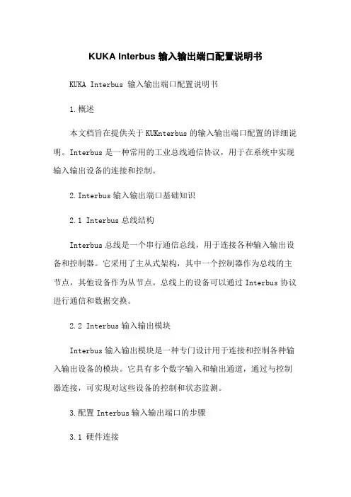
KUKA Interbus 输入输出端口配置说明书KUKA Interbus 输入输出端口配置说明书1.概述本文档旨在提供关于KUKnterbus的输入输出端口配置的详细说明。
Interbus是一种常用的工业总线通信协议,用于在系统中实现输入输出设备的连接和控制。
2.Interbus输入输出端口基础知识2.1 Interbus总线结构Interbus总线是一个串行通信总线,用于连接各种输入输出设备和控制器。
它采用了主从式架构,其中一个控制器作为总线的主节点,其他设备作为从节点。
总线上的设备可以通过Interbus协议进行通信和数据交换。
2.2 Interbus输入输出模块Interbus输入输出模块是一种专门设计用于连接和控制各种输入输出设备的模块。
它具有多个数字输入和输出通道,通过与控制器连接,可实现对这些设备的控制和状态监测。
3.配置Interbus输入输出端口的步骤3.1 硬件连接首先,将Interbus输入输出模块与控制器进行物理连接。
这通常包括连接输入输出模块的电源线和总线连接线到控制器的相应接口。
3.2 软件设置在控制器的软件界面中,进入Interbus配置页面。
根据实际情况,选择Interbus输入输出模块的型号和配置参数。
这些参数通常包括总线地质、节点地质、通信速率等。
3.3 输入输出配置在Interbus配置界面中,根据连接的输入输出设备的类型和数量,进行输入输出通道的配置。
可以设置每个通道的输入输出方式(如开关量输入、模拟量输入、开关量输出等)和相应的参数(如输入信号类型、输出信号电平等)。
4.附件- 附件1:Interbus输入输出模块说明书- 附件2:控制器使用手册5.法律名词及注释- Interbus:一种工业总线通信协议,用于实现输入输出设备的连接和控制。
- 输入输出模块:专门设计用于连接和控制各种输入输出设备的模块。
- 总线:指用于数据交换的通信线路。
- 主从式架构:一种通信架构,其中一个设备作为总线的主节点,其他设备作为从节点。

XMC4500 Satellite-kit: Automation I/O Kit Part Number: KIT_XMC4X_AUT_ISO_001Features∙Connection to CPU board via ACT Satellite Connector∙ISOFACE OUT, up to 8 channels∙ISOFACE IN, up to 8 channels∙I2C based IO expander up to 8 channels∙Single side assembly of all parts∙ 2 LEDs indicating power (3.3 Volt, 5 Volt)∙Power supply:-Power jack for external 24V supply-From CPU Board via ACT Satellite ConnectorPLEASE SEE THE FOLLOWING PAGES FOR USERS MANUALHexagon Application Kit For XMC4000 FamilyAUT_ISO-V1Automation I/O CardBoard User's Manual Revision 1.0, 2012-02-28Edition 2012-02-28Published byInfineon Technologies AG81726 Munich, Germany© 2012 Infineon Technologies AGAll Rights Reserved.Legal DisclaimerThe information given in this document shall in no event be regarded as a guarantee of conditions or characteristics. With respect to any examples or hints given herein, any typical values stated herein and/or any information regarding the application of the device, Infineon Technologies hereby disclaims any and all warranties and liabilities of any kind, including without limitation, warranties of non-infringement of intellectual property rights of any third party.InformationFor further information on technology, delivery terms and conditions and prices, please contact the nearest Infineon Technologies Office ().WarningsDue to technical requirements, components may contain dangerous substances. For information on the types in question, please contact the nearest Infineon Technologies Office.Infineon Technologies components may be used in life-support devices or systems only with the express written approval of Infineon Technologies, if a failure of such components can reasonably be expected to cause the failure of that life-support device or system or to affect the safety or effectiveness of that device or system. Life support devices or systems are intended to be implanted in the human body or to support and/or maintain and sustain and/or protect human life. If they fail, it is reasonable to assume that the health of the user or otherTrademarks of Infineon Technologies AGAURIX™, C166™, CanPAK™, CIPOS™, CIPURSE™, EconoPACK™, CoolMOS™, CoolSET™, CORECONTROL™, CROSSAVE™, DAVE™, EasyPIM™, EconoBRIDGE™, EconoDUAL™, EconoPIM™, EiceDRIVER™, eupec™, FCOS™, HITFET™, HybridPACK™, I²RF™, ISOFACE™, IsoPACK™, MIPAQ™, ModSTACK™,my-d™, NovalithIC™, OptiMOS™, ORIGA™, PRIMARION™, PrimePACK™, PrimeSTACK™, PRO-SIL™, PROFET™, RASIC™, ReverSave™, SatRIC™, SIEGET™, SINDRION™, SIPMOS™, SmartLEWIS™, SOLID FLASH™, TEMPFET™, thinQ!™, TRENCHSTOP™, TriCore™.Other TrademarksAdvance Design System™ (ADS) of Agilent Technologies, AMBA™, ARM™, MULTI-ICE™, KEIL™, PRIMECELL™, REALVIEW™, THUMB™, µVision™ of ARM Limited, UK. AUTOSAR™ is licensed by AUTOSAR development partnership. Bluetooth™ of Bluetooth SIG Inc. CAT-iq™ of DECT Foru m. COLOSSUS™, FirstGPS™ of Trimble Navigation Ltd. EMV™ of EMVCo, LLC (Visa Holdings Inc.). EPCOS™ of Epcos AG. FLEXGO™ of Microsoft Corporation. FlexRay™ is licensed by FlexRay Consortium. HYPERTERMINAL™ of Hilgraeve Incorporated. IEC™ of Commission Electrotechnique Internationale. IrDA™ of Infrared Data Association Corporation. ISO™ of INTERNATIONAL ORGANIZATION FOR STANDARDIZATION. MATLAB™ of MathWorks, Inc. MAXIM™ of Maxim Integrated Products, Inc. MICROTEC™, NUCLEUS™ of Mentor Graphics Corporation. Mifare™ of NXP. MIPI™ of MIPI Alliance, Inc. MIPS™ of MIPS Technologies, Inc., USA. muRata™ of MURATA MANUFACTURING CO., MICROWAVE OFFICE™ (MWO) of Applied Wave Research Inc., OmniVision™ of OmniVision Technologies, Inc. Openwave™ Openwave Systems Inc. RED HAT™ Red Hat, Inc. RFMD™ RF Micro Devices, Inc. SIRIUS™ of Sirius Satellite Radio Inc. SOLARIS™ of Sun Microsystems, Inc. SPANSION™ of Spansion LLC Ltd. Symbian™ of Symbian Software Limited. TAIYO YUDEN™ of Taiyo Yuden Co. TEAKLITE™ of CEVA, Inc. TEKTRONIX™ of Tektronix Inc. TOKO™ of TOKO KABUSHIKI KAISHA TA. UNIX™ of X/Open Company Limited. VERILOG™, PALLADIUM™ of Cadence Design Systems, Inc. VLYNQ™ of Texas Instruments Incorporated. VXWORKS™, WIND RIVER™ of WIND RIVER SYSTEMS, INC. ZETEX™ of Diodes Zetex Limited.Last Trademarks Update 2011-02-24Table of ContentsTable of Contents1Overview (7)1.1Key Features (7)1.2Block Diagram (8)2Hardware Description (8)2.1ISOFACE OUT (9)2.2ISOFACE IN (9)2.3IO Expander (10)2.4Power (11)2.5Satellite Connector (12)3Production Data (13)3.1Schematics (13)3.2Layout and Geometry (16)3.3Bill of Material (17)List of FiguresFigure 1Automation I/O Card (AUT_ISO-V1) (8)Figure 2Automation I/O Card Interfaces (8)Figure 3Power Circuit (11)Figure 4ACT Satellite Connector (12)Figure 5Satellite Connector Type ACT (12)Figure 6Satellite Connector, IO Expander, Power (14)Figure 7ISOFACE (15)Figure 8Automation I/O Card Layout (16)List of TablesTable 1ISOFACE OUT Connector Pinout (9)Table 2ISOFACE OUT signal connection to the Satellite Connector (9)Table 3ISOFACE IN Connector Pinout (9)Table 4ISOFACE IN signal connection to the Satellite Connector (10)Table 5GPIO channel LED/SMD pad mapping (10)Table 6IO Expander I2C signal connection to the Satellite Connector (10)Table 7Power LED’s (11)Table 8PowerScale Jumper (11)Table 9Automation I/O Card BOM (17)OverviewIntroductionThis document describes the features and hardware details of the Automation I/O Card (AUT_ISO-V1) designed to work with Infineon’s XMC4500 CPU board. This board is part of Infineon’s Hexagon Application Kits.1 OverviewThe AUT_ISO-V1 board is an application expansion satellite card of the Hexagon Application Kits. The satellite card along with a CPU board (e.g. CPU_45A-V2 board) demonstrates ISOFACE capabilities together with XMC4500. The focus is safe operation under evaluation conditions. The satellite card is not cost optimized and cannot be seen as reference design.1.1 Key FeaturesThe AUT_ISO-V1 satellite card is equipped with following featuresConnection to CPU board (e.g. CPU_45A-V2) via satellite connector ACTISOFACE OUT, up to 8 channelsISOFACE IN, up to 8 channelsI2C based IO expander up to 8 channelsPower supplyo Powerjack for external 24 V supplyo From CPU board via ACT satellite connector1.2Block DiagramFigure 1 shows the block diagram of the AUT_ISO-V1 satellite card. There are following building blocks:Figure 1Automation I/O Card (AUT_ISO-V1)2 Hardware DescriptionThe following sections give a detailed description of the hardware and how it can be used.Figure 2 Automation I/O Card InterfacesISOFACE OUT (ISO1H812G)ISOFACE IN (ISO1I811T)Power 3.3 V (IFX1763SJV33)ISOFACE IN ConnectorACT Satellite ConnectorPower Jack24 V2.1 ISOFACE OUTISOFACE output device used in AUT_ISO-V1 satellite card is ISO1H812G. It is supplied by VDD3.3 on the CPU side and VDD24 for the ISOFACE OUT side. VDD24 and GNDISO can to be connected either by X300 or by X240(24 V external power jack). This is the same net that supplies the DC/DC converter. VDD24 is +24 Vdc (referred to GNDISO)Table 1 below gives the signal details of ISOFACE OUT connector.Table 12 below gives the details of SPI signal connection to the satellite connector.2.2 ISOFACE INISOFACE input device used in AUT_ISO-V1 satellite card is ISO1I811T. It is supplied by 3.3 V on the CPU side and VBB (24V) for the ISOFACE IN side. VBB and GNDBB need a separate connection to 24 V external power source through connector X320.Resistor R337 is used on board for setting input type to IEC61131-2 Type 1.Resistors R326 and R327 sets the frequency of ISOFACE IN to 100 kHz (default).Table 3 gives the details of ISOFACE IN connector pin mapping.Table 3 ISOFACE IN Connector PinoutISOFACE IN shares the same SPI lines with ISOFACE OUT except the chip select as shown in Table 4.2.3 IO ExpanderThe AUT_ISO-V1 satellite card supports GPIO expansion though I2C IO-Expander on board (U230). The I2C Address for IO expander device is 0x1001000X. The satellite card supports 8 such GPIO’s. All t he GPIO’s are connected to LEDs (V230-V237) and SMD-Pads (TP230 – TP237). The Table 5 gives the GPIO channel and corresponding LED/PAD mapping.Table 6 shows the connection of the IO Expander device to the ACT satellite connector.2.4 PowerThe AUT_ISO-V1 satellite card can be supplied by an external power supply (24 V / 1 A) to be connected to the power jack X240 or by a 5 V supply via the 80-pin ACT satellite connector. An external power supply is necessary only in case the current coming via the ACT satellite connector is not sufficient.A DC-DC converter on board (U240) steps down the input voltage from the power jack X240 to 5 V (VDD5). The input voltage can be in the range from 12 V to 24 V. An on board linear voltage regulator is generating a 3.3 V (VDD3.3) power supply out of the VDD5.Figure 3 Power CircuitA Diode V242 protects the reverse flow of current to an external source. Therefore a simultaneous power supply of the satellite boards via both the power jack and the satellite connector with not harm.LED V210 indicates the presence of 5 V power and LED V211 indicates the presence of 3.3 V power.Table 7 Power LED’sThe AUT_ISO-V1 satellite card supports a PowerScale probe for power measurement purpose.Table 8 PowerScale Jumper2.5 Satellite ConnectorThe satellite connector of the AUT_ISO-V1 satellite card interfaces it’s the signals to a CPU board e.g. CPU_45A-V2. Take care to connect the ACT satellite card always to the corresponding ACT satellite connector of the CPU board only.Figure 4 ACT Satellite ConnectorThe signal mapping of the ACT satellite connector and correponding CPU function are provided in figure 6Figure 5 Satellite Connector Type ACT3 Production Data3.1 SchematicsThis chapter contains the schematics for the Automation I/O Card:Satellite Connector, IO Expander, PowerISOFACEFigure 6 Satellite Connector, IO Expander, PowerFigure 7 ISOFACE3.2 Layout and GeometryFigure 8 Automation I/O Card Layout3.3 Bill of MaterialTable 9 Automation I/O Card BOMTable 9 Automation I/O Card BOMw w w.i n f i n e o n.c o m。
![海湾消防GST-LD-8303输入-输出模块安装说明书[1]](https://uimg.taocdn.com/6931ba06de80d4d8d15a4f60.webp)
安装、使用产品前,请阅读安装使用说明书GST-LD-8301输入/输出模块安装使用说明书(Ver.1.02,2008.02)一、概述GST-LD-8301输入/输出模块(以下简称模块),主要用于连接需要火灾报警控制器控制的消防联动设备,如排烟阀、送风阀、防火阀等,并可接收设备的动作回答信号。
二、特点1.输出可设置为有源输出或无源输出方式。
2.输入、输出具有检线功能。
3.输入端可现场设为常开检线、常闭检线或自回答方式,可与无源触点连接。
4.地址码为电子编码,可由电子编码器事先写入,也可由控制器直接更改,工程调试简便可靠。
5.电路部分和接线底壳采用插接方式,接触可靠、便于施工。
三、技术特性1.工作电压:信号总线电压:总线24V 允许范围: 16V~28V电源总线电压:DC24V 允许范围:DC20V~DC28V2.工作电流:总线监视电流≤1mA 总线启动电流≤3mA电源监视电流≤5mA 电源启动电流≤20mA3.输入检线:常开检线时线路发生断路(短路为动作信号)、常闭检线输入时输入线路发生短路(断路为动作信号),模块将向控制器发送故障信号4.输出检线:输出线路发生短路、断路,模块将向控制器发送故障信号5.输出容量:无源输出:容量为DC24V/2A,正常时触点阻值为100kΩ,启动时闭合,适用于12V~48V直流或交流有源输出:容量为DC24V/1A6.输出控制方式:脉冲、电平(继电器常开触点输出或有源输出,脉冲启动时继电器吸合时间为10s)7.指示灯:红色(输入指示灯:巡检时闪亮,动作时常亮;输出指示灯:启动时常亮)8.编码方式:电子编码方式,占用一个总线编码点,编码范围可在1~242之间任意设定9.线制:与火灾报警控制器采用无极性信号二总线连接,与电源线采用无极性二线制连接10.使用环境:温度: -10℃~+55℃相对湿度≤95%,不凝露11.外形尺寸:86mm×86mm×43mm(带底壳)12.壳体材料和颜色:ABS,瓷白13.重量:约145g(带底壳)14.安装孔距:60mm15.执行标准:GB 16806-2006四、结构特征与工作原理1.模块外形示意图如图1所示。

DEVICE SPECIFICATIONSNI 65891 Gbps, 20 Channel, LVDS Digital I/O Adapter ModuleThis document lists specifications for the NI 6589 adapter module. Pair these specifications with the specifications listed in your FlexRIO FPGA module specifications document or your Controller for FlexRIO specifications document.Caution The protection provided by the NI 6589 can be impaired if it is used in amanner not described in this document.Caution To avoid permanent damage to the NI 6589, disconnect all signalsconnected to the NI 6589 before powering down the module, and only connectsignals after the module has been powered on by the FlexRIO FPGA module or theController for FlexRIO.Note All numeric specifications are typical unless otherwise noted. All graphsillustrate the performance of a representative module.Caution To ensure the specified EMC performance, operate this product only withshielded cables and accessories.Specifications are subject to change without notice. For the most recent device specifications, visit /manuals.ContentsFlexRIO Documentation (2)Channel Specifications (3)Single-Ended Channel (PFI, CLOCK IN) (4)LVDS Channels (DDC) (4)Clocking (6)EEPROM Map (6)Power (6)Physical (7)Environment (7)Operating Environment (7)Storage Environment (7)Shock and Vibration (7)Compliance and Certifications (8)Safety (8)Electromagnetic Compatibility (8)CE Compliance (9)Online Product Certification (9)Environmental Management (9)FlexRIO Documentation2| | NI 6589 SpecificationsTable 1. FlexRIO Documentation Locations and Descriptions (Continued)Channel SpecificationsNumber of connectors 2 SMA (PFI 0 and CLOCK IN) and1 InfiniBand (Digital Data & Control, or DDC) Number of digital I/O channels23 total on DDC (16 LVDS data, 4 LVDS PFI,and 3 single-ended PFI)Direction control of digital I/O channels Per channelNumber of clock input terminals2, CLOCK IN (SMA) and STROBE (DDC) Number of clock output terminals1, DDC CLK OUTNI 6589 Specifications| © National Instruments| 3Single-Ended Channel (PFI, CLOCK IN)Maximum data rate100 Mb/sMinimum required time to tristate 6 nsGeneration (PFI, CLOCK IN)Table 2. Generation Voltage Levels (100 µA load)Output impedance50 Ω, nominalMaximum per channel DC drive strength±18 mAOutput protection Single-ended I/O can indefinitely sustain ashort to any voltage between -0.5 V and 3.8 Vwith a current not exceeding 30 mA. Acquisition (PFI, CLOCK IN)Input impedance50 kΩ, nominalInput protection-0.5 V to 4.6 VNote Internal diode clamps may begin conducting outside the 0 V to 3.3 V range.LVDS Channels (DDC)Part number of LVDS buffers SN65LVDT100 (Texas Instruments)Power-up state Data direction set to input, 110 Ω differentialimpedance with 1.62 kΩ to 3.3 V on theinverted pins, and 1.62 kΩ on the noninvertedpins.4| | NI 6589 SpecificationsMaximum data rate 1 Gb/s (per channel)Minimum required direction change500 µslatencyNote For more information about using 16 channels in parallel, refer to the Xilinxapplication note available at the following website: /support/documentation/application_notes/xapp860.pdf.Generation (Data, DDC Clock Out)Output protection Each channel can indefinitely sustain a short toany voltage between 0 V and 4.3 V.Note Internal diode clamps may begin conducting outside the 0 V and 3.3 V range.Acquisition (Data, STROBE)Note Input V oltage values apply to any combination of common-mode or inputsignals.Input impedance110 Ω differential, nominalInput protection Each channel can indefinitely sustain a short toany voltage between 0 V and 4.3 V.Note Internal diode clamps may begin conducting outside the 0 V to 3.3 V range.NI 6589 Specifications| © National Instruments| 5ClockingPart number of crosspoint switch DS90CP04 (National Semiconductor)Si570, Grade B (Silicon Labs)Part number of adapter module onboardclock10 MHz to 810 MHzFrequency range of adapter moduleonboard clockResolution of adapter onboard clock0.1 Hz, maximum by design45% to 55%Duty cycle of adapter module onboardclockNote For more specifications and information about the Si570 clock chip, refer tothe Si570 datasheet available at the Silicon Labs website, . EEPROM MapCaution Only write to User Space. Writing to any other byte address may causethe NI 6589 to stop functioning.Power+12 V210 mA, 2.51 W, typical+3.3 V770 mA, 2.53 W, typicalV ccoA290 mA, 710 mW, typicalV ccoB0 mA6| | NI 6589 SpecificationsPhysicalDimensions12.9 × 2.0 × 12.5 cm (5.1 × 0.8 × 4.9 in.) Weight302 g (10.6 oz)Front Panel Connectors 2 SMA and one 73-pin InfiniBand connectorEnvironmentMaximum altitude2,000 m (800 mbar) (at 25 °C ambienttemperature)Pollution Degree2Indoor use only.Operating EnvironmentAmbient temperature range0 °C to 55 °C1 (Tested in accordance withIEC 60068-2-1 and IEC 60068-2-2. MeetsMIL-PRF-28800F Class 3 low temperaturelimit and MIL-PRF-28800F Class 2 hightemperature limit.)Relative humidity range10% to 90%, noncondensing (Tested inaccordance with IEC 60068-2-56.) Storage EnvironmentAmbient temperature range-20 °C to 70 °C (Tested in accordancewith IEC 60068-2-1 and IEC 60068-2-2. MeetsMIL-PRF-28800F Class 3 limits.)Relative humidity range5% to 95%, noncondensing (Tested inaccordance with IEC 60068-2-56.)Shock and VibrationOperating shock30 g peak, half-sine, 11 ms pulse (Tested inaccordance with IEC 60068-2-27. MeetsMIL-PRF-28800F Class 2 limits.) 1For PXI/PXI Express chassis configurations that group NI FlexRIO adapter modules in three ormore contiguous slots, National Instruments recommends limiting the ambient temperature to less than 50 °C.NI 6589 Specifications| © National Instruments| 7Random vibrationOperating 5 Hz to 500 Hz, 0.3 g rmsNonoperating 5 Hz to 500 Hz, 2.4 g rms (Tested in accordancewith IEC 60068-2-64. Nonoperating testprofile exceeds the requirements ofMIL-PRF-28800F, Class 3.) Compliance and CertificationsSafetyThis product is designed to meet the requirements of the following electrical equipment safety standards for measurement, control, and laboratory use:•IEC 61010-1, EN 61010-1•UL 61010-1, CSA 61010-1Note For UL and other safety certifications, refer to the product label or the OnlineProduct Certification section.Electromagnetic CompatibilityThis product meets the requirements of the following EMC standards for electrical equipment for measurement, control, and laboratory use:•EN 61326-1 (IEC 61326-1): Class A emissions; Basic immunity•EN 55011 (CISPR 11): Group 1, Class A emissions•AS/NZS CISPR 11: Group 1, Class A emissions•FCC 47 CFR Part 15B: Class A emissions•ICES-001: Class A emissionsNote In the United States (per FCC 47 CFR), Class A equipment is intended foruse in commercial, light-industrial, and heavy-industrial locations. In Europe,Canada, Australia, and New Zealand (per CISPR 11), Class A equipment is intendedfor use only in heavy-industrial locations.Note Group 1 equipment (per CISPR 11) is any industrial, scientific, or medicalequipment that does not intentionally generate radio frequency energy for thetreatment of material or inspection/analysis purposes.Note For EMC declarations, certifications, and additional information, refer to theOnline Product Certification section.8| | NI 6589 SpecificationsCE ComplianceThis product meets the essential requirements of applicable European Directives, as follows:•2014/35/EU; Low-V oltage Directive (safety)•2014/30/EU; Electromagnetic Compatibility Directive (EMC)Online Product CertificationRefer to the product Declaration of Conformity (DoC) for additional regulatory compliance information. To obtain product certifications and the DoC for this product, visit / certification, search by model number or product line, and click the appropriate link in the Certification column.Environmental ManagementNI is committed to designing and manufacturing products in an environmentally responsible manner. NI recognizes that eliminating certain hazardous substances from our products is beneficial to the environment and to NI customers.For additional environmental information, refer to the Minimize Our Environmental Impact web page at /environment. This page contains the environmental regulations and directives with which NI complies, as well as other environmental information not included in this document.Waste Electrical and Electronic Equipment (WEEE)EU Customers At the end of the product life cycle, all NI products must bedisposed of according to local laws and regulations. For more information abouthow to recycle NI products in your region, visit /environment/weee.电子信息产品污染控制管理办法(中国RoHS)中国客户National Instruments符合中国电子信息产品中限制使用某些有害物质指令(RoHS)。

光电纠偏控制器使用说明书一、接线及输入输出端口说明1#为对边对线光电头输出插口,即可作对边检测口作用,又可作对线检测口作用,三芯航空插接口。
可配一般光电头如Z3N-TB22使用。
2#为对线光电头输入插口,可作对线检测口作用,三芯航空插接口。
可配一般光电检测器使用。
3#为四芯光电检测器(如ZPS-2系列槽形双路光电头)输出插口,既可作对边检测口作用,又可作对线检测口作用。
7和8为左限位开关输入端口,接左限位开关常开触头。
9和10为右限位开关输出端口,接右限位开关常开触头。
交流同步电机的红色、黄色、白色和蓝色四线对应接入6、5、4、3四个接线端子。
(调换红色与蓝色接线可改变电机旋转方向。
)220V电源接入1、2两接线端子。
二、运行前的准备工作1、接线:按接线图要求将电源,电机,限位开关,光电头对应接好。
2、电机方向极性确定:(如按手动键,使控制器处于手动状态,再按极性正键),则按键,电机正方向旋转,材料活动架往左移动,按键,电机反方向旋转,材料活动架往右移动,如电机旋转方向与实际相反,可将电机红蓝两线调换接线.3、限位开关控制电机停止方向确定:(如按手动键,使控制器处于手动状态,再按极性正键), 则按键,电机正方向旋转,后碰触活动架移动方向的限位开关,电机运转停止,则表示限位有效,反之则碰触一端限位开关,电机应运转停止,则表示限位开关接线相反,必须给予调换.注意:检验限位开关时必须在电机运转的有效行程内,必须在手动档检验,否则一但限位失灵将损坏电机丝杆的机械结构。
4、材料对边或对线选择:对于材料首先确定它的基准位置是材料边缘还是印刷线条。
确定跟踪边缘以后,再确定左边缘还是右边缘,以后再决定电机方向极性。
对于印刷品的线条一般定于2MM以上线条作为对边处理。
反之则作为对线处理。
5、光电头的定位、调整:按自动键、对边对线键,确定是跟踪材料边缘或印刷线条后,将光斑对准材料边缘或印刷线条,调整光电头位置观察光电头上的指示灯,指示灯从亮-暗-亮,则表示设定成功,若无该状态,则无基准工作。
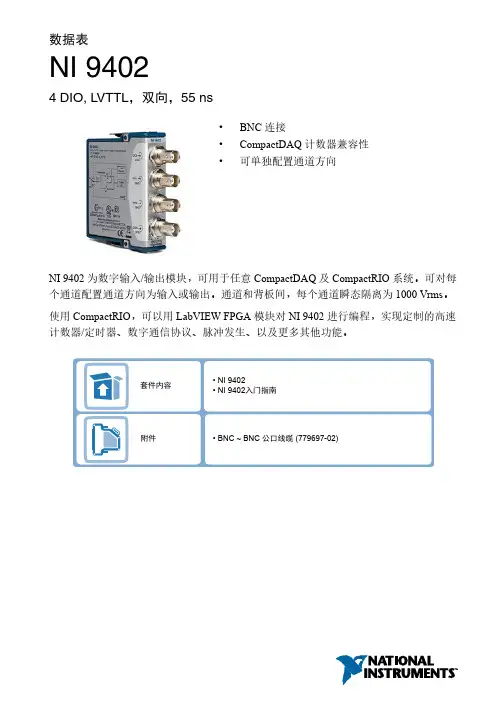
数据表NI 94024 DIO, LVTTL ,双向,55 ns•BNC 连接•CompactDAQ 计数器兼容性•可单独配置通道方向NI 9402为数字输入/输出模块,可用于任意CompactDAQ 及CompactRIO 系统。
可对每个通道配置通道方向为输入或输出。
通道和背板间,每个通道瞬态隔离为1000 Vrms 。
使用CompactRIO ,可以用LabVIEW FPGA 模块对NI 9402进行编程,实现定制的高速计数器/定时器、数字通信协议、脉冲发生、以及更多其他功能。
• NI 9402• NI 9402入门指南• NI 9940 后壳套件 (779567-01) 套件内容附件• BNC ~ BNC 公口线缆 (779697-02)NI C 系列概述NI 提供超过100种C 系列模块,用于测量、控制以及通信应用程序。
C 系列模块可连接任意传感器或总线,并允许进行高精度测量,以满足高级数据采集及控制应用程序的需求。
•与测量相关的信号调理,可连接一组传感器和信号•隔离选项包括组间、通道间以及通道对地•温度范围为-40 °C ~70 °C ,满足各种应用程序和环境需要•热插拔CompactRIO 和CompactDAQ 平台同时支持大部分C 系列模块,用户无需修改就可将模块在两个平台间转换。
CompactRIOCompactRIO 将开放嵌入式架构与小巧、坚固以及C 系列模块进行了完美融合,是一种由NI LabVIEW 驱动的可重配置I/O (RIO )架构。
每个系统包含一个FPGA ,用于自定义定时、触发以及处理一系列可用的模块化I/O ,可满足任何嵌入式应用程序的需求。
2 | | NI 9402数据表CompactDAQCompactDAQ是一种便携、耐用的数据采集平台,其模块化I/O集成了连接、数据采集以及信号调理功能,可直接接入任意传感器或信号。
配合LabVIEW使用CompactDAQ,用户可轻松地定义如何采集、分析、可视化以及管理测量数据。
GM718输入/输出模块使用说明书北京市密云区经济开发区汇通街17号1号楼邮编101500 电话4006964119 网址第1页/共2页1.概述GM718输入/输出模块主要用于控制防火卷帘、消防电梯、门禁系统等需要开关量控制且有反馈信号的消防设备。
火警时,控制器通过输入/输出模块启动需要联动的外控设备。
设备动作后,模块将设备动作的反馈信号上传至火灾报警控制器。
2.特点△满足GB16806-2006《消防联动控制系统》相关技术要求。
△消防二总线,无极性。
△具有输入端断路检测功能;具有反馈检测功能(短路即反馈)。
△具有无源输出线路短路、断路检测功能。
△具有一组常开和一组常闭节点输出。
△具有线路故障检测功能可通过电子编码器进行配置。
△具有自反馈功能可通过电子编码器进行配置。
△启动输出方式(电平启动或者脉冲启动)可通过控制器进行选择。
△断路或短路报反馈可通过电子编码器进行配置。
3.主要技术特性1)线制:信号二总线,无极性2)总线电压:DC 24V,无极性3)总线电流:监视电流:≤0.6mA;反馈电流:≤0.8mA4)输出动作指示灯:红色5)输入动作指示灯:红色6)负载容量:DC 24V/1A或AC 220V/1A7)使用环境:温度:0℃~+50℃;相对湿度:<95%(40±2℃)8)外形尺寸:L85mm×W85mm×H36mm9)执行标准:GB 16806-20064.工作原理及结构特征4.1工作原理当控制器收到火警联动信号或者手动启动信号时,控制器向模块发出启动命令,模块收到启动命令后将无源常开触点闭合,无源常闭触点断开,并点亮输出动作指示灯。
当输入/输出模块配接的外部设备动作时,监视的模块就会检测到启动信号(输入动作指示灯常亮)并且将信号反馈到火灾报警控制器主机上而实现反馈。
4.2结构特征图1 输入/输出模块结构与安装尺寸图5.操作说明5.1系统配置1)GM718输入/输出模块需配接国泰公司生产的G7系列控制器使用。
台达EtherCAT 分散式从站模块R2-EC0902数位输入继电器输出模块使用手册绵密网络 专业服务中达电通已建立了70余个分支机构及服务网点,并塑建训练有素的专业团队,提供客户最满意的服务,公司技术人员能在2小时内回应您的问题,并在48小时内提供所需服务。
中达电通公司版权所有如有改动,恕不另行通知400 - 820 - 9595地址:上海市浦东新区民夏路238号邮编:201209电话:( 021 )5863-5678传真:( 021 )5863-0003网址: 扫一扫,关注官方微信沈阳电话:(024)2334-1160哈尔滨电话:(0451)5366-5568长春电话:(0431)8892-5060呼和浩特电话:(0471)6297-808北京电话:(010)8225-3225天津电话:(022)2301-5082济南电话:(0531)8690-6277太原电话:(0351)4039-485郑州电话:(0371)6384-2772石家庄电话:(0311)8666-7337上海电话:(021)6301-2827南京电话:(025)8334-6585杭州电话:(0571)8882-0610合肥电话 :(0551)6281-6777武汉电话:(027)8544-8475南昌电话:(0791)8625-5010成都电话:(028)8434-2075长沙电话:(0731)8549-9156重庆电话:(023)8806-0306 昆明电话:(0871)6313-7362广州电话:(020)3879-2175厦门电话:(0592)5313-601南宁电话:(0771)2621-501乌鲁木齐电话:(0991)4678-141兰州电话:(0931)6406-725西安电话:(029)8836-0780贵阳电话:(0851)8690-1374福州电话:(0591)8755-1305序言感谢您使用本产品,本使用手册提供R2-EC0902 EtherCAT远程控制32通道数位输入/32通道继电器输出扩充模块的相关信息。
安装、使用产品前,请阅读安装使用说明书一、GST-LD-8301输入/输出模块安装使用说明书(Ver.1.09,2020.11)注意事项1.产品仅应被安装在产品安装使用说明书所明示规定的使用环境,不适用于有易燃性物质、有爆炸性物质或有腐蚀性物质的场所(包括使用磷化铝杀虫剂的烟草仓库)。
产品不可被安装在对设备有特殊认证要求的环境或场所(包括但不限于爆炸性环境、船舶、飞机、火车、机动车等交通工具)。
如有特殊需求,请联系本公司相应销售人员。
2.请注意模块触点只适用于控制低于48V的直流或交流,严禁用来控制AC220交流,以防强交流干扰信号损坏模块或控制设备!对于需要控制AC220V的情况,需配接GST-LD-8302模块实现。
3.模块输出触点端子COM和NO间有几十千欧电阻,导致工作时有微弱检线电流!不宜控制微弱电流启动设备!4.部分防火卷帘控制器、电梯控制箱等设备因其采用比较器或逻辑电平类输入、启动电流微小,容易受到线路或空间干扰自身产生误动作,不建议客户使用。
如果必须使用,应参照被控设备的说明书在GST-LD-8301模块和被控设备间加中间继电器解决。
5.本模块不能用于控制气体灭火设备!6.用户应定期维护与模块有电气连接的被控设备(包括但不限于按照《建筑防烟排烟系统技术标准》(GB51251-2017)的规定每半年对全部排烟防火阀、送风阀或送风口、排烟阀或排烟口进行自动和手动启动试验一次,每年对全部防烟、排烟系统进行一次联动试验和性能检测等),以防止被控设备的机械部分由于质量问题或者遭受污染腐蚀等状况时,导致被控设备不能正常动作的风险。
由于用户自身原因或被控设备自身状况等我司之外的原因导致包括被控设备不能正常动作在内的任何直接或间接损失,我司不承担任何责任。
二、概述GST-LD-8301输入/输出模块(以下简称模块),主要用于连接需要火灾报警控制器控制的消防联动设备,如排烟阀、送风阀、防火阀等,并可接收设备的动作回答信号。
控制器信号输入输出说明书一、引言本文档为控制器信号输入输出说明书,旨在为使用者提供对控制器的信号输入输出进行全面的了解和操作指引。
本说明书详细介绍了控制器的信号输入和输出接口,包括接口定义、功能描述以及使用方法。
二、信号输入接口1. 电源输入接口电源输入接口用于将外部电源与控制器连接,以供控制器正常运行。
该接口采用标准的插孔连接,用户只需将电源线插入控制器的电源输入接口,并确保电源稳定可靠。
2. 通信输入接口控制器的通信输入接口用于接收外部设备发送的通信信号,实现与其他设备的数据交互。
用户可以根据需要选择合适的通信接口,如以太网接口、RS232接口、RS485接口等,通过连接相应的通信线缆将外部设备与控制器连接。
3. 传感器输入接口传感器输入接口用于连接各类传感器,以获取外部环境的信息并进行相应的控制。
用户可根据需要选择合适的传感器类型,并将其与控制器的传感器输入接口连接。
常见的传感器类型包括温度传感器、湿度传感器、压力传感器等。
4. 开关量输入接口开关量输入接口用于接收开关信号,实现对控制器的开关量输入控制。
用户可通过连接相应的开关装置将其与控制器的开关量输入接口连接,实现对设备的启停、状态检测等功能。
三、信号输出接口1. 控制信号输出接口控制信号输出接口用于将控制器的输出信号传输给其他设备,实现对其进行控制。
用户可根据所需控制类型选择相应的输出接口类型,如开关量输出接口、模拟量输出接口等。
通过连接相应的输出线缆,用户可以将控制器的输出信号传输到需要控制的设备。
2. 报警输出接口报警输出接口用于实现对外部设备的报警控制,用户可根据需要选择相应的报警输出方式,如声音报警、灯光报警等。
通过连接相应的报警装置,将其与控制器的报警输出接口连接,当控制器检测到异常情况时,会触发报警信号输出。
3. 电源输出接口电源输出接口可以为外部设备提供电力支持,用户可通过连接相应的设备,将其与控制器的电源输出接口连接,实现对设备的供电。