minecraft格雷科技说明书
- 格式:pdf
- 大小:7.22 MB
- 文档页数:88
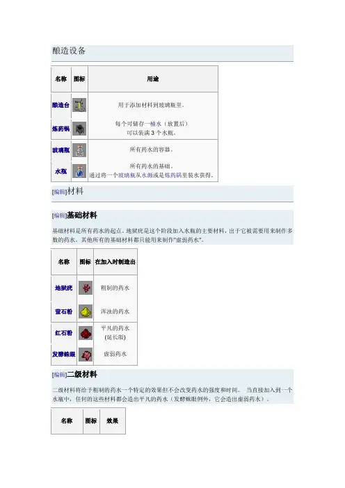
名称图标用途酿造台用于添加材料到玻璃瓶里。
炼药锅每个可储存一桶水(放置后)可以装满3个水瓶。
玻璃瓶所有药水的容器。
水瓶所有药水的基础。
通过将一个玻璃瓶从水源或是炼药锅里装水获得。
[编辑]材料[编辑]基础材料基础材料是所有药水的起点。
地狱疣是这个阶段加入水瓶的主要材料,出于它被需要用来制作多数的药水。
其他所有的基础材料都只能用来制作"虚弱药水"。
名称图标在加入时制造出地狱疣粗制的药水萤石粉浑浊的药水红石粉平凡的药水(延长版)发酵蛛眼虚弱药水[编辑]二级材料二级材料将给予粗制的药水一个特定的效果但不会改变药水的强度和时间。
当直接加入到一个水瓶中,任何的这些材料都会造出平凡的药水(发酵蛛眼例外,它会造出虚弱药水)。
岩浆膏防火糖移动加速闪烁的西瓜瞬间治疗蜘蛛眼中毒恶魂之泪生命恢复烈焰粉力量增强发酵蛛眼力量减弱金萝卜夜视能力[编辑]三级材料三级材料会改变药水的属性。
"时间加长"和"效力增强"的版本可以无限地互换。
名称图标加入时红石粉加长时间萤石粉增强效力发酵蛛眼腐化效果[note 1]火药使药水可投掷[编辑]药水[编辑]基础药水所有的基础药水都是通过在水瓶里加入单个材料制作而来的。
平凡的药水和虚弱药水可以和火药结合来创造出对应的喷溅药水。
药水材料酿造设置效果可导向粗制的药水地狱疣+水瓶无治疗药水抗火药水剧毒药水再生药水力量药水迅捷药水平凡的药水(延长版)红石粉+水瓶无虚弱药水(延长版)平凡的药水恶魂之泪,闪烁的西瓜,烈焰粉,岩浆膏,糖,或蜘蛛眼+水瓶无虚弱药水浑浊的药水萤石粉+水瓶无虚弱药水对所有的近身攻击减少的伤害。
药水材料酿造设置效果持久(分钟)治疗药水闪烁的西瓜+粗制的药水每瓶恢复。
瞬间抗火药水岩浆膏+粗制的药水给予对火,岩浆,和烈焰人的远距离攻击的免疫力。
3:00再生药水恶魂之泪+粗制的药水随着时间的推移恢复生命。
0:45力量药水烈焰粉+粗制的药水对所有的近身攻击添加的伤害,无论有没有使用武器。

READ AND SAVE THESE INSTRUCTIONSTechnical SpecificationsCheck the fan label to make sure it is the correct voltage.Operating voltage Diameter Weight Operating frequency120 VAC, 1 Φ52 in. (132 cm)11 lb (5 kg)60 Hz 220/240 VAC, 1 Φ52 in. (132 cm)11 lb (5 kg)50/60 HzTools Needed• Ladder• Wire Strippers• Phillips Screwdriver • Hex Key •WrenchesModels: L3127-X5, L3127-X6, FR127C-U1EXXScan or visit /support for online Haiku mobile app helpMounting Bracket Control Box Wiring Cover LED Diffuser Ring Mounting Ball & Hardware Lower Cover Trim Lower Cover Ring Extension Tube Motor Unit (3) Airfoils Remote Control Hardware PackPARTScdef2REV. H 8/27/2019 | © 2015 BIG ASS FANS | ALL RIGHTS RESERVEDHARDWAREHardware and tools needed for installation are packaged in the hardware pack. Hardware below shown at actual size.Mounting Hardware M8 Bolt M8 Washer M8 Nylock NutAirfoil Hardware(6) M5 Screws with Tooth WasherWiring Cover Hardware(4) M4 Socket Head Cap ScrewsLower Cover HardwareMounting Ball & HardwareSteel PinWedge4 mm Self-TappingScrewMounting Ball(2) Painted M3.5 Screws or3HAIKU® BY BIG ASS FANSPREPARE THE FAN SITEInstallation requires basic electrical knowledge. Contact a licensed electrician if you are uncomfortable performing electrical work!21Disconnect Power!Disconnect power to the fan location before wiring fan!If required by your local electrical code, a licensed electrician must install the fan.A means for disconnection must be incorporated in thefixed wiring in accordance with the wiring rules.If you are installing your fan to an outlet box, it must be suitable for fan support . If there is not an outlet box at the fan location,install one on a ceiling joist or beam.INSTALL THE MOUNTING BRACKETa4REV. H 8/27/2019 | © 2015 BIG ASS FANS | ALL RIGHTS RESERVED5HAIKU® BY BIG ASS FANSSecure the mounting bracket (a ) to the outlet box (b ) with the screws supplied with the outlet box (c ). Outlet Box Hardware:c. Screw (supplied with outlet box)STEP COMPLETED6REV. H 8/27/2019 | © 2015 BIG ASS FANS | ALL RIGHTS RESERVEDPREPARE THE AIRFOILS312SELECT LENS(BLACK FANS WITH LIGHTS)MATCH AIRFOIL STICKERS7HAIKU® BY BIG ASS FANS21Black fans with lights: For softer lighting, remove the white lens and install the smoky lens before attaching the airfoils.a. Twist to uninstall white lens.b. Twist smoky lens to lock in place.Make sure the stickers on the airfoils match the stickers on the fan hub.Rest the motor assembly (a ) on your lap. Moving clockwise, install each airfoil (b ) with the provided hardware. Tighten the screws to 2.5 N·m (22.1 in·lb). Do not use power tools to install the airfoils, and do not over-tighten the screws! Over-tightening the screws may cause the airfoils to warp and void your warranty.Airfoil Hardware:c. (6) M5 screws with tooth washerFans without lights: Position the motor cover (d ) over the motor, and then place both hands flat on the cover and turn it clockwise to lock it in place.DO NOT USE POWER TOOLS!STEP COMPLETED211Lower the extension tube (a) onto the motor shaft. Ensure the yellow arrow sticker on the extension tube is aligned with the sticker on the motor.CONNECT MOTOR WIRING AND SECURE EXTENSION TUBERemove the tie holding the wiring harnesses to the extension tube. Plug the two large wiring harnesses (a ) into the receptacles on the motor. Plug the small, male wiring harness (b ) into the female wiring harness from the motor shaft.Align the bolt holes on the extension tube with the holes on the motor shaft, and then secure the tube with the provided hardware and wrenches.Mounting Hardware:21Place the lower cover ring (a ) around the extension tube, resting it evenly on the motor. There should be a very small gap between the cover and the airfoils. Rotate the cover ring clockwise until it stops.Thread the wires through the opening in the lower cover trim (b ), and then slide the trim down the extension tube, resting it evenly on the cover ring.Align the screw holes on the trim with the motor screw holes, and then secure the trim in place with the provided screws (c ).213ARRANGE LED DIFFUSER RING, WIRING COVER, AND MOUNTING BALLcSlide the LED diffuser ring (a ), wiring cover (b ), and mounting ball (c ) down the extension tube (in that order), resting them on the fan hub.Do not seat the LED diffuser ring in the wiring cover at this step!ATTACH THE MOUNTING BALLSEAT MOUNTING BALL INSTALL WEDGEInsert the steel pin (a ) into the hole at the top of the extension tube, and then slide the mounting ball upward, seating the steel pin in the inner slots of the ball.Mounting Ball Hardware:a. Steel pinInsert the wedge (b ) into the mounting ball as shown, and then secure the wedge with the screw (c ). Tighten the screw enough to prevent movement between the mounting ball and extension tube. Do not over-tighten 21Raise the fan to the mounting bracket. Align the slot in the mounting ball with the rib in the mounting bracket, insert the mounting ball, and let the fan hang freely.Gently twist the extension tube to ensure the mounting ball is properly seated and will not move during fan operation.STEP COMPLETED21INSTALL THE UPPER EARTH/GROUND WIRERoute the ground wire from the extension tube (a) to the outside of the mounting bracket. Secure the ground wire terminal (b) to the mounting bracket with the screw (c).STEP COMPLETEDMake sure power is disconnected before wiring the fan!Do not connect the fan to a damaged power source! Do not attempt to resolve electrical failures on your own. Consult a qualified electrician if uncertain of the electrical installation of this fan.Make the electrical connections by securing the supply power wires to the loose ends of the wiring harness (a ) with the provided wire nuts.Test the connection by lightly tugging on the wires.Tuck the power wiring and wire nuts into the outlet box.321Insert the control box (a ) into the mounting bracket as illustrated. Be careful not to pinch the wires between the mounting bracket and control box!Snap the LED indicator (b ) into the gap in the mounting bracket. Make sure it is securely seated.21CONNECT THE CONTROL BOX2CONNECT WIRING HARNESSES29HAIKU® BY BIG ASS FANS Connect the wiring harness from the control box (a ) to the harness from the junction box (b ).Peel the backing off the double-sided tape (c) on the mounting bracket, and then affix the harnesses to the tape.Connect the wiring harnesses from the extension tube (d ) to the corresponding receptacles (e ) on the control box.12INSTALL THE WIRING COVER30REV. H 8/27/2019 | © 2015 BIG ASS FANS | ALL RIGHTS RESERVED31HAIKU® BY BIG ASS FANS Slide the wiring cover (a ) up the extension tube, aligning the yellow arrow stickers so that the top of the wiring cover sits flush with the mounting bracket. Make sure the LED indicator receptacle shows through the opening in the cover (b ).Make sure all wiring is tucked into the wiring cover, and then secure the cover with the provided screws (c ).Wiring Cover Hardware:c. (4) M4 socket head cap screwsSlide the LED diffuser ring (d ) up the extension tube and plugthe connector into the LED indicator receptacle through theopening (b ) in the wiring cover.Make sure the tabs on the diffuser ring are securely snappedin place.12STEP COMPLETED332REV. H 8/27/2019 | © 2015 BIG ASS FANS | ALL RIGHTS RESERVEDTEST THE FANDo not expose the remote control to rain or water.Turn on power to the fan location and test functionality using the remote. Turn on the fan and test speed and light brightness*.*Applies only to fans with lightsTurns fan on or off.Sets fan timer length of up to eight hours.Each press extends timer by one hour.Turns light on or off.Clears active fan timer.Increases fan speed/light brightness.Varies fan speed to simulate a naturalbreeze.Decreases fan speed/light brightness.Automatically adjusts your fan speedovernight to keep you comfortable whileyou sleep.For operation, maintenance, and troubleshootinginformation, visit /supportUnited States 2348 Innovation DriveLexington, KY 40511+1 855 694 2458© 2015 Big Ass FansThe information contained in this document is subject to change without notice. May be protected by one or more patents listed at /patentsHaiku is a trademark of Delta T LLC, registered in the U.S. and/or other countries.For warranty information, visit /product-warrantiesCanada 2180 Winston Park Drive Oakville, Ontario L6H 5W1Canada1 844-924-4277Mexico CEBSA (Corporación Eléctrica del Bravo SA de CV)Avenida Ind. Rio San Juan Lote 3-A Parque Industrial del Norte Reynosa, Tamps C.P. 88736/+52 1 899 925 6398。

EN 60204-1机械电气系统安全需求旸致科技股份有限公司Sunreach Technology Co., Ltd. TEL:(04)24758336 FAX:(04)24758230目录第5章电源入线及切断装置 (4)5.1节电源入线 (4)5.2节外部接地系统 (4)5.3节电源断电装置 (4)5.4节防意外起动之切断装置 (5)5.5节个别电气设备的断电装置 (5)5.6节未经授权、意外及/或错误开启的保护 (5)第六章触电保护 (6)6.2节直接触电保护 (6)6.3节间接触电保护 (7)6.4节超低压保护(PELV) (7)第七章设备的保护 (7)7.2节过电流保护 (7)7.3节马达的过载保护 (8)7.4节异常温度 (8)7.5节电源中断或电压降低与随后电力恢复的保护 (8)7.6节马达过速度保护 (8)7.7节接地失效/残余电流保护 (8)7.8节相序保护 (8)7.9节因闪电及开关涌流而造成过电压的保护 (9)第八章等电位键结 (9)8.2节保护性键结电路 (9)第九章控制电路与控制功能 (10)9.1节控制电路电源 (10)9.2节控制功能 (10)9.3节保护互锁 (12)9.4节绝缘失效时的控制功能 (13)第十章操作者接口与机器外部之控制装置 (13)10.1节安装与位置 (13)10.2节按钮开关 (14)10.3节指示灯及显示 (14)10.4节照光式按钮开关 (14)10.5节旋转式控制装置 (15)10.6节启动装置 (15)10.7节紧急停止装置 (15)10.8节紧急切断装置 (15)10.9节显示装置 (15)11.2节基本需求 (15)11.3节可程序设备 (16)第十二章控制机构: 位置,安装与电气箱 (16)12.1节一般需求 (16)12.2节位置与安装 (16)12.3节保护等级 (17)12.4节电气箱,门及开孔 (17)12.5节控制机构的接近 (18)第十三章导线与电缆线 (18)13.2节导线 (18)13.3节绝缘 (18)13.4节电流承载量 (18)13.5节导线与电缆线电压降 (18)13.6节最小线径需求 (19)13.7节可挠性电缆线 (19)13.8节集电线、集电条与集电环组合 (19)第十四章配线实务 (20)14.1节连接与线路 (20)14.2节导线的辨认 (20)14.3节电气箱内配线 (21)14.4节电气箱外配线 (21)14.5节导线槽,接线盒及其它接线箱 (22)第十五章电动马达与相关设备 (23)15.1节一般需求 (23)15.2节马达外壳 (24)15.3节马达尺寸 (24)15.4节马达安装与隔间 (24)15.5节马达选用的准则 (24)15.6节机械性煞车保护装置 (25)第十六章附属设备及照明 (25)16.1节附属设备 (25)16.2节机器与设备的局部照明 (25)第十七章标志,警告标示及参考名称 (26)17.1 节一般需求 (26)17.2 节警告标示 (26)17.3 节功能辨认 (26)17.4 节控制设备的标示 (26)17.5 节参考名称 (27)18.1节一般通则 (27)18.2节须提供的数据 (27)18.3节文件需求 (27)18.4节基本数据 (27)18.5节安装图 (28)18.6节方块(系统)图与功能图 (28)18.7节电路图 (28)18.8节操作手册 (28)18.9节维修手册 (28)18.10节组件表 (28)第十九章测试与检查 (28)19.1 节一般需求 (29)19.2 节保护性键结电路的连续性 (29)19.3 节绝缘电阻测试 (29)19.4 节耐压测试 (30)19.5 节残存电压防护 (30)19.6 节功能性测试 (30)19.7 节重测 (30)附录一: 何谓IP保护等级 (31)附录二: 导线的等级 (31)第5章电源入线及切断装置5.1节电源入线1. 建议机器电控系统的电源供给为单一电源。

C hirstmas editon工业2说明书:完整版by johnbanq ——————————————资源篇——————————————————1.新增基础矿物:铜矿:在地下70层到10层可以找到,大多用来制造铜电缆和青铜(比例15:10)锡矿:在地下40层以下可以找到,大多用来制造好用的电池和空槽铀矿:64层以下就可以找到的矿物,用途只有1个==就是发电2.非矿物类新增基础资源:橡胶树:这玩意的树干。
看起来像屎黄色==最大的特点是头上那点树叶子(这玩意非常蛋疼,你开游戏把画质开到流畅度优先,这玩意的树叶还是不变)用处呢,自然很简单,在找到橡胶树后先打掉叶子找树种,还有可采取洞:找到后拿木龙头右击就可以吸到原胶了————————资料————————————————————————————橡胶树的生成取决于地形,Taiga地形有0%-6%的几率每chunk生成3个Forest地形有2%-12%的几率每chunk生成1-6个Swampland地形有10%-20%的几率每个chunk生成5-15个橡胶树的可采取洞:这样子:每个橡胶木有25%的几率成为可采取状态,每棵树最大同时产生3个(几率很小,除非你走运)————————————基础矿物篇——————————————————————本章主要介绍各种工业的矿锭钢:这个东西是由铁锭在炉子中烧成的,制成机器的必备品铜:这个东西是由铜矿或者铜粉烧制而成的,主要用来制作电缆锡:这个矿是由锡矿或者锡粉烧成的,主要用来制作电池或者空槽(尤其是电池,这玩意在初期很有用)青铜:这玩意是工业之路上必须要的(扳手要),但与其他矿不同,这个不是挖到的,是合成出来的,合成步骤:1.先把铜矿和锡矿打粉(要打粉机和发电机)2.再这样子合成青铜粉:3.再烧青铜粉,你就得到青铜了铀锭:这个东西在初期,或者不玩核电的话,就是废柴1个获得方法:将铀矿放进压缩机,你就得到铀锭了_________________________基础工具篇____________________________________________本章主要介绍初期到中期的可合成工具青铜工具系列:这些工具的耐久度大于铁1点(350次),但是速度没铁快合成方法跟铁或者黄金工具差不多,这里只用稿子举例:青铜装备系列:与工具一样,耐久度多了30%,算是不错的:(合成方法跟其他装备1样,用胸甲举例)当然,青铜的最大用处是扳手:扳手算是工业中最重要的工具之一!因为,你觉得拿稿子去拆机器会得到机器?做梦去吧!那只会得到碎片!可惜,虽然有扳手,但还是有4分之一的可能性手残(拆成机器方块)不过这玩意有耐久,你也可以把扳手升级为电动扳手,那样就只用充电了,HAYO!当然,你还记得我上上章提到的木龙头么?就是这货了主要用来提取:这样橡胶木的橡胶当然,IC2的线缆系统也引入了绝缘系统(这些详见系统说明书,这里就少说为好)这个东西可以增加或者剪掉其右击线缆的绝缘层(左击剪掉,右击增加)当你有1个巨大的布线系统或者1个精巧的系统要布置怎么办?这个东西可以给线缆涂上漆!漆的颜色不同的电缆不会相连接,只会连接没有的或者同颜色的上色例子(所有颜色都可以)(这玩意还有秘密用途,暂时保密)工业2还增加了建设泡沫,这玩意的合成下面会讲到,为了快速喷洒泡沫,就一定要用到这个东西了:它的喷洒范围是这样的:当然,你也可以用脚手架来搭配使用:在那个图标处喷泡沫,空格子里就会填满泡沫_______________初期:电子工具专篇____________________________本专篇介绍初期的电子工具.OD SCANNER!这玩意可以自动计算你脚下5*5范围内的矿石数目,再与总方块1除,就会显示数据数据越高自然越好自然,IC2的线缆系统越来越复杂了,so,我们需要1个测量EU的表(Electric unit能量单位缩写)来测量电压,毕竟烧掉线缆或者炸掉机器可不是小事情!好了,你是不是对那些用完就嗝屁的,几乎是浪费资源的稿子,铲子感到厌烦了?那么,试试这些电子装备系列吧!电钻!这个东西不仅1个替代了2个工具的作用,甚至还更快!(实际上有些稿子拆的慢的这个拆的快)当然,你也可以升级电钻!钻石电钻!这玩意采矿就是光速!对了,我说过没?这玩意甚至可以挖黑曜石!而且比钻石稿子更快!钻肯定有时候是不够用的,自然也需要锯!这玩意砍树也自然光速,对了,这玩意的攻击力相当于钻石剑!更HAYO的是,你可以享受这些而只用充电!要是你觉得充电还是麻烦,就用这个把!传说中的电池包!________________________初期物品合成____________________________好了,虽然工具中有很多不知道的东西,在这章,我们都会解答:首先,在线缆之前,提提橡胶橡胶就是把这玩意(原胶)烧(或者放进提取器,橡胶多点)就得到了好了,从最基础的开始!线缆!铜线,图片说明1切XD对了,这玩意的承受上限为32EU(batbox输出等级)电力损耗表:种类EU/格损耗未绝缘铜线0.3 3.33格1EU绝缘铜线0.25格1EU铜线是合成所有机器(电路)的基础物品!金线,这东西是铜线的进阶(可承受电压升到128EU,MFE输出等级)图片排列是未绝缘绝缘绝缘2倍绝缘2倍绝缘电力损耗表:种类EU/格损耗未绝缘金线0.52格1EU绝缘金线0.45 2.22格1EU2倍绝缘金线0.4 2.5格1EU这个东西主要用来中压运输高压线,这个东西的可承受电压为512EU和2048EU(MFS输出等级和超高压输出等级)[虽然损耗不小,但是对于512EU或者2048EU来讲不算什么]图片排列:未绝缘绝缘绝缘2倍绝缘2倍绝缘3倍绝缘3倍绝缘3倍绝缘损耗表:种类EU/格能量损耗未绝缘高压线1每格1EU绝缘高压线0.95每1.05格1EU2倍绝缘高压线0.9每1.11格1EU3倍绝缘高压线0.8每1.25格1EU接下来介绍种特别的电缆,这些电缆无法绝缘,也无法涂漆:当当当当!锡线!这玩意只能传输5EU(众人;那用来干毛?)这个东西主要用于太阳能(损耗特低,40格才1EU)当然,介绍2种。

OmniViewEnergy Sequencer CondenserCompressor EvaporatorThe intuitive touch for refrigeration,heating and gas compression controlGEA Omni control panelGEA Omni offers what operators expect from a control panel: maximum efficiency and reliable operation of their system. This advanced, industrial control panel integrates and optimally coordinates all required system components, resulting in a demand- d riven and highly energy-efficient facility operation.High-definition, easy-to-use HMIFeaturing a 15.6-inch, high-definition (1366 x 768 pixels) colordisplay, the GEA Omni h uman-machine interface (HMI) provides clear visualization of drawings, images, and text. Furthermore, GEA Omni incorporates single- and multiple-finger gestures used in many modern consumer electronics,adding an instinctive aspect to paging through selections and zooming documents or historical graphs. An intuitive menu system, where the information you need remains only a touch or two away, ensures routine functions are easy to perform by non-technical personnel. On-screen buttons and c ommands required for daily operations have been clearly and logically grouped and includes Omni’s QR code function, which creates a quick operating data report by simply scanning the QR code on the main compressor screen. The GEA Omni HMI makes membrane keypads and tedious navigation obsolete.One solutionGEA Omni has been designed as an open system. As a result, it can monitor and c ontrol not only the relevant components from GEA, but also those from other companies.C onfiguration of the control system and the operation modes takes place initially at the GEA factory and then may be adjusted during commissioning on-site, directly at the GEA Omni. The system openness makes it an all-inclusive command center, e liminating the need for auxiliary control systems. GEA Omni shows operating states not only for main components, but also for ancillary equipment. Whether it be monitoring and managing the position of a valve or the operation of a pump, the entire refrigeration, heating or gas compression system can be controlled from one panel.The “Classic” view gives operators essential information that’s easy to check at a glance, even from a distance.Live operating data can be captured using the QR-code scanner from a mobile device.3GEA Omni Sketch provides graphical representations showing real-time operating data. Featuring multi-page availability, this data can be shown on illustrations of your choice, i.e. floor plan, 3D drawing, PFD, photo. Colors add visual emphasis. OmniSketch provides the illustrations our customers use the most, without the need for an additional SCADA system.Authorized maintenance staff and service companies can access GEA Omni from remote locations.This OmniSketch example illustrates a typical refrigeration systemlayout with key status information.In addition to its visually stunning and intuitive HMI, the GEA Omni control panel a ppeals to not only operators but system integrators as well. As it comes from the f actory, GEA Omni satisfies typical industrial communication standards (Modbus TCP, EtherNet/IP, Modbus RTU, Allen-Bradley DF1 and standard options Profibus-DP and Profinet) for purposes of data exchange with auxiliary, supervisory control and data acquisition (SCADA) and building managment systems.Moreover, a standard Ethernet interface is provided that enables the use of wireless technology and smart phone or tablet viewing capability. Use a VNC viewer app on your smart device to easily connect to the IP address of your GEA Omni panel. Combined with a secure connection, you have 24/7 access to your system. Authorized service staff and service companies can access the control system remotely. GEA Omni also sends email and text message notifications to on-site and off-site personnel, ensuring proactive response to system conditions that need immediate attention.Instructional videos add a dynamic, visual element to the Documentation section.Digital contentDrawings, manuals, reports and videos are easily accessible for on-screen viewing, which can prove to be i nvaluable during new system commissioning, day-to-day operation, maintenance and troubleshooting. Every GEA Omni includes supporting documentation from the factory. In addition, users can create or provide their own videos and PDF documents that can easily be stored and retrieved via the USB port in the panel door, or via an Ethernet connection using OmniLink, for example:• Operating manuals• Process Safety Management documents (PSM)• Electrical wiring diagrams• Piping and instrumentation diagrams • Mechanical drawings • Component specifications• Standard Operating Procedures (SOPs)• Logic diagrams• Service and maintenance reports • Videos in AVI, MP4, or WMV formatAll important documents, such as wiring, piping & instrumentation diagrams andmanuals, are a finger tap away.5High-definition display15.6" display with 1,366 x 768 resolutionUnique user setup and auditing Create 25 unique users and monitor usage/actionsGEA OmniLinkRemotely view, manage andautomatically backup all dataConfigurable communication Read and write information to and from othercontrollers without additional wiringProjective-capacitive,multi-touch technologyNatural and intuitive operationMonitor the present – analyze the pastIntegrated apps keep you in touch with your equipmentGEA OmniLinkIncluded with every GEA Omni control panel is GEA OmniLink – a stand-alone M icrosoft Windows © operating system application designed to automatically find GEA Omni p anels on the same Ethernet network, read panel status, perform automatic data backup and reporting and view the present panel screen as ifv iewing the panel on-site. This application provides a convenient means of t ransferring configurations, programs, historical data, and parameters over an E thernet network without the need to insert a USB memory device into the panel.Enjoy remote access to your entire GEA control system via GEA OmniLink. Pictured are four compressor tiles with visual indication of current operating statuses.The IT security and data protection can be and must be adjusted as per customer’s needs under customer’s responsibility. GEA Omni control panel, including its various software applications, does not warrant any particular needs or customer’s level of IT security or data protection. The level of data protection and/or IT security for access, handling and transmission of data remains the customer’s sole responsibility. Specific security measures or requirements defined by the customer may be supported and provided by GEA upon request and after consultation and agreement.89Analyze past operating data, such ascompressor pressures and temperatures,with GEA OmniHistorian.GEA OmniHistorianGEA OmniHistorian is a M icrosoft Windows© operating systemapplication used to view and a nalyze historical data. GEA Omnistores years of operating information at a u ser- d efined samplingrate. This information consists of input/output (I/O) data, eventlogs, parameters, energy analysis, maintenance, revisions, andannunciations, which can be easily transferred over E thernetusing GEA OmniLink. Furthermore, GEA OmniHistorian cancreate custom reports, and viewable data can be printed orexported to XLS-formatted files.Secure – right out of the boxUp to 25 unique users can be created, each with a customizable view of operating data. Each unique user’s login history and actions are recorded in the panel for auditing purposes. Control parameters may be adjusted only within allowable limits, andall changes are logged in the panel’s history for security and administrative review. As a result, GEA Omni helps to minimize operator mistakes and system failure. GEA Omni provides three levels of security – Operator, Service, and Administrator.Operator level can:• Monitor parameters and equipment status• Select operational modes and personalize data views • Analyze historical data• Observe and manage annunciations and error reports • Change language and engineering unitsIn addition, the Service level can:• Modify all parameters and settings• Download program and configuration updates• Define operator- and service-level users• Troubleshoot I/O system with advanced on-screendiagnostic tools• Display real-time status of customized program logicIn addition, the Administrator level can:• Modify control system configuration• Securely access GEA Omni with an encrypted file,eliminating the use of a common password• Change the compressor selection and control optionsThe panel interior is designed toprovide clear and easy installationand serviceability. 10Reliable hardwareGEA Omni is a modular design, featuring a robust I/O system of standard industrial components. The compact space utilization of this I/O system allows for more devices to be controlled in a single panel. In addition, the Ethernet-based design allows for flexibility of remote I/O in separate enclosures, all of which are inter c onnected using standard Ethernet cabling.Layout and wiringThe interior of the GEA Omni exhibits well-organized separation of high- and low- v oltage sections, providing safe and simple wiring. Uniform connection design, clear labeling, and color coding contribute to easy installation. All control wiring to field d evices is terminated in a dedicated panel section. Thanks to the flexible methodof i nterconnecting I/O system components, wiring is kept to a minimum. These features allow fast inspectionand commissioning.Field configurabilityDoes the screw compressor have an economizer solenoid that was not accounted for in the panel configuration?Is the oil pump operation different than preconfigured on the control panel? These common issues during a retrofit panel installation will no longer require a ssistance from the factory. GEA Omni offers authorized personnel thefl exibility to modify the configuration and reassignthe I/O system to suit the needs of the a pplication.Energy ManagementEnergy costs are typically a facility’s largest operating expense. But with the GEA Omni control panel’s abundant capabilities, which include the effective management of energy usage, that operating expense can be significantly reduced. GEA Omni’s Energy functions are designed to enable users to effectively reduce operating costs by finely controlling key aspects of their process to utilizethe minimal amount of energy required. In addition, Omni’s Recipe functionality makes it fast and easy to change multiple parameters, based on time and date,to optimize running conditions.Through a fine-tuned approach to compressor control and sequencing, condenser control and sequencing, refrigerant vessel and pump control, evaporator control and a myriad of reactive and proactive energy management techniques, GEA Omni’s Energy functions deliver where it counts most – on the bottom line – and contributes to the achievement of companies’ sustainability-related goals by reducing their carbon footprints.In addition, GEA Omni’s Smart Sequencer option automatically prioritizes the compressors with the best part-load performance, ensuring high energy efficiency. Variable-speed-driven compressors can be grouped and speed synchronized, reducing energy consumptionand extending the lifetime of the equipment.One global product – GEA peace of mind Manufactured in North America, Europe, and Asia,GEA Omni meets the needs of a global customerbase. Preconfigured in more than 30 languages,GEA Omni carries the benefit of global salesand support. Rest easy knowing your facilityis controlled by a product that is invented, manufactured and supported by a globalleader in refrigeration, heating and gascompression control panel technology.GEA Omni’s Energy Management function allows operators toevaluate system energy usage and adjust to reduce operating costs.11G E A -R T -O M N I 7757-3000-001 (p k g o f 20) (r e v . 10-21) © G E A S y s t e m s N o r t h A m e r i c a L L C . A l l r i g h t s r e s e r v e d . S u b j e c t t o m o d i fi c a t i o n . P r i n t e d i n t h e U S A . T h e i n f o r m a t i o n c o n t a i n e d i n t h i s b r o c h u r e m e r e l y s e r v e s a s a n o n -b i n d i n g d e s c r i p t i o n o f o u r p r o d u c t s a n d i s w i t h o u t g u a r a n t e e . B i n d i n g i n f o r m a t i o n , i n p a r t i c u l a r r e l a t i n g t o c a p a c i t y d a t a a n d s u i t a b i l i t y f o r s p e c i fi c a p p l i c a t i o n s , c a n o n l y b e p r o v i d e d w i t h i n t h e f r a m e w o r k o f c o n c r e t e i n q u i r i e s .“Engineering for a better world” is the driving and energizing principle connecting GEA ’s workforce. As one of the largest systems suppliers, GEA makes an important contribution to a sustainable future with its solutions and services, particularly in the food, beverage and pharmaceutical sectors. Across the globe, GEA ’s plants, processes and components contribute significantly to the reduction of CO2 emissions, plastic use as well as food waste in production.GEA is listed on the German MDAX and the STOXX ® Europe 600 Index and also included in the DAX 50 ESG and MSCI Global Sustainability indexes.We live our values.Excellence • Passion • Integrity • Responsibility • GEA-versityGEA Refrigeration Technologies GEA Systems North America LLC 3475 Board Road York, PA 17406Tel717 767 6411**********************************************/refrigeration。

等价交换wiki说明(EE)等价交换wiki说明BY 凤歌笑⽪丘本说明依据英⽂wiki整理⽽成,仅仅为了⽅便中国MC玩家使⽤。
请保留署名⾮商业传播,仅基于材料更新的⽬的予以更改。
为了⽅便系统理解,添加了⼀些个⼈说明并且调整物品的顺序。
合成表基于V6版本,其他版本可能会有所不同,也许有些功能也会不同。
因为没有统⼀中⽂译名,所以有些名字可能是我在胡说⼋道。
请善⽤搜索功能.部分数值在单⼈游戏和多⼈游戏中可能不同。
在⽂中会出现某种物品使⽤这样那样的能源,很多是旧版本的遗留,现在基本上所有物品可以从能量之星中汲取能源了。
0.0贤者之⽯贤者之⽯有着多种⽤途,是任何有志⽓的炼⾦师起步之地。
很多年轻的炼⾦师认为制造贤者之⽯是炼⾦艺术的顶点,他们实在是误⼊歧途,这仅仅是打开通向转化表的⼀道门。
现实转化可以通过右键或者按住shift右键转化在⽯头、圆⽯、草地、沙⼦、沙砾之间转化,可以按R将⼀个mod转化成另⼀个。
这个功能在V6⾥已经被去掉了。
转化列表,在EE2⾥⾯很多列表被删去,剩下的有这些:0.0.1转化桌基本功能:转换桌有两种形式,⼀个类半砖的固定桌和⼀个可以在热键栏中使⽤的便携桌,两个都提供让你在有⾜够的EMC的情况下将⼀种东西变成另⼀种。
在左边放⼊输⼊物品,右边会出现接近于输⼊物品EMC数值并且你对它有⾜够了解的东西。
注意放置⼀叠物品的时候,仅仅会将其视为⼀个物品。
将物品放在右边的中⼼会将⽬标定为那个物品,将物品放在“burn”那个位置,会⽴刻从其中提取出EMC,不必使⽤反物质继电器。
在它基础的状态,这个转化桌仅仅能创造⼀般的物质(⽅块)和燃料(煤以及其他)⽤差不多的EMC,在你烧掉了糖⽽没有提取EMC的时候,再放上红⽯是会失败的。
即使在你找到解锁的⽅法以后,你最后烧掉的东西和还在输⼊栏内的东西对于你可以制造的东西还是有影响的。
炼⾦术之路:⼀个新⼈炼⾦术师并没有随⼿操纵秩序的⼒量。
炼⾦初学者必须学会如何将⼀个物质转换成另⼀个,你需要获得物品,将他们放进去做实验,通过已经知道的物质能量关系来推断,判断他们存在的实质。

GasAlertMicroClip XL SpecificationsThe instrument must satisfy the following:Physical SpecificationsSize (h x w x d) Physical size shall be no larger than 4.4 x 2.4 x 1.2 in. / 11.3 x 6.0 x 3.2 cmWeight Weight of instrument shall be no more than 6.7 oz. / 190 g, including aligator clip.Case Material Case material shall be rugged, impact-resistant, non-corrosive composite material that will preventspark generation and shall be available in highly visible safety yellow or black.Integral Boot The instrument shall be equipped with a built-in concussion-proof boot.Vibrator Alarm The detector shall be equipped with an internal vibrator alarm for high noise areas.Handling Unit shall easily attach to pocket or belt.Carrying Attachments Unit shall be equipped with a high-tension stainless steel alligator clip.Accessories The following accessories must be available:• A manual aspirator pump with sampling hose or probe• A vehicle charger•Confined space entry kits in a hard-sided carrying case•Automatic Test and Calibration Station that shall:o Bump test and calibrate instruments in the field without requiring use of a desktop PC orlaptopo Be fully portable and available in a variety of portable kit optionso Provide simultaneous management of up to 6 instrument docking moduleso Include battery and 110-240 VAC line power optionso Include software for downloading, evaluating and archiving monitoring resultsUser InterfacesDisplay Type Large alphanumeric LCD (Liquid Crystal Display) type display with simultaneous and continuousreadouts for each gas monitored in ppm, %LEL and % v/v values, as applicable, showing the real-time gas concentrations present.Digits not to be less than 0.260 in. / 6.50 mm high.Display Symbols (Icons) Gas alarm icons will clearly identify alarm type, gas hazard and alarm level encountered, low battery condition, instrument status, safe display, stealth, and calibration steps.Keypad/Switches One-button operation must: activate the detector; run the self-test; display alarm setpoints; displaypeak gas exposures and clears them; calibrate and zero. There shall be no requirement to accesshidden switches for any instrument operation.Monitoring CapabilityConfigurations The gas detector must be available in 1, 2, 3, or 4 gas models that continuously and simultaneously monitor for oxygen, combustible/methane gases, hydrogen sulfide, carbon monoxide as applicable.Gases Detected and Measuring Specifications Gases Standard Measuring Range In Increments of: Hydrogen Sulfide 0-100 ppm H2S 1 ppm Carbon Monoxide 0-500 ppm CO 1 ppm Oxygen 0-30.0 % O20.1 % Methane 0-5% v/v methane 0.1% methane Combustible gases 0-100% LEL 1.0% LELSensor Type Sensors must be plug-in.Longer Life The catalytic (combustible/methane) sensor should not be affected by common sulfur compounds, such as H2S.Instrument PowerBattery Type and Run Time Lithium-polymer rechargeable battery pack. The run time of a new instrument shall not be less than 18 hours at room temperature. The run time shall not be less than 12 hours at any time over 2 years of use in a temperature range between -4°F to +122°F (-20°C to +50°C)Rechargeable Choices A Vac (110 to 240) line charger, 12 Vdc (vehicle) charger and 12 Vdc / 24 Vdc cable must beavailable.Charge Time Typical charge time for rechargeable batteries shall not be more than 6 hours per battery.EnvironmentalTemperature Range Normal operation: -4 to +122 °F / -20 to +50 °CHumidity 0-95% RH (non-condensing) continuousIngress Protection IP 68CalibrationAutomatic Calibration Calibration must be fully automatic with Auto Zero and Auto Span functions. Instrument must advise as each automatic function takes place and when to apply gas. Calibration span levels must be “UserSettable”.Calibration Diagnostics Equipped with calibration diagnostics protection that ensures a valid calibration, the detector mustcheck the ambient air and the calibration gas. If either does not meet expected values, the detectorwill refuse calibration and automatically exit the procedure, retaining all previous values.Basic Operational FeaturesInstrument Activation One-button activation. ON function must:•Test the battery and advise condition•Display the current alarm set points•Provide a full function self-test of sensor integrity, circuitry integrity and alarm activation•Automatically calibrate the oxygen sensor•Automatically zero H2S, CO and LEL sensors•Advise when the next calibration is due in days, or advise the number of days overdueInadvertent Shut-off Unit must not be able to be turned OFF accidentally and will incorporate a timed off function thatprovides audible/visual/vibration OFF indications.Peak Exposures Records peak (maximum) exposure to gases encountered and must display the reading on demand.Accumulated Exposures Records both TWA (time-weighted average) to toxic gases based on an 8-hour workday and STEL(short-term exposure limit) to toxic gases based on a 5-15 minute user-selectable work period.(STEL period is adjustable.) Must display readings on demand.Confidence Beep Confidence beep must be a user selectable option.IntelliFlash (ComplianceIntelliFlash verifies operation and compliance to both the user and supervisor.Flash)Instrument Status Advise The detector must constantly analyze and test its own operational status and provide alarm advice of any malfunction.Backlight Backlight automatically illuminates the display in all alarm conditions (auto with time-out) and can be reactivated on demand with a button press.Adjustable Options The unit shall be equipped with user options for the following functions:•Adjust STEL period (5-15 minutes in 1 minute intervals)•Set calibration span levels and due date•Toggle ON/OFF: confidence beep, oxygen auto-calibration at start-up, Auto-zero LEL, CO andH2S on start-up, latching alarms, “SAFE” display function (does not display gas concentrationsunless readings change), stealth mode for silent operations, Force calibration when calibrationoverdue, Calibration lockout: calibration must be invoked via IR, mandatory bump test option,bump test reminder•Multi-language LCD selection in English, French, German, Portuguese and Spanish•Select combustible gases measurement: 0-100% LEL (Lower Explosive Limit) or Methane gas 0-5.0% v/v•Alarm setpoint disable (set to zero for off).•Calibration due date (1 to 365 days, or set to zero for off)•User-settable confidence beep•Individual sensor enable/disable.Auto Zero Protection Must be able to activate Auto Zero at any time. To ensure a valid Auto Zero, the instrument will firsttest the ambient air for background interfering gas before proceeding with the Auto Zero function.Instrument AlarmsAlarms and Type Simultaneous visual display alarms, audible alarms and vibrator alarms must warn in the event of agas alarm condition, sensor fault or instrument status alarm.Number of Gas Alarms Must be equipped with four (4) user-settable alarm levels, including instant low, instant high, TWA(Time- weighted average) and STEL (short-term exposure limit). Also, will include an OL (over limit)alarm.Visual Alarms Instrument must be equipped with at least three flashing alarm bars easily visible from multipleangles. The backlight must light in all alarm conditions. LCD must provide positive clear alarm adviceas to which alarm level and type has been exceeded (instant LOW, instant HIGH, TWA, STEL and/orover limit).Audible Alarm Instrument must be equipped with one variable pulsed audible alarm that shall be rated at 95+ dB. Vibrator Alarm Instrument must be equipped with an internal vibrator alarm for high noise areas.Alarm Set points Alarm set points must be adjustable. The current alarm set points shall be displayed each time onstart-up.Over Limit Exposure Protection For exposures above the instrument’s measuring range for the combustible sensor, the instrument will provide an over limit latching alarm that must be acknowledged.Low Battery Warning Must be equipped with low battery audible and visual alarms.DataloggingRecorded All events and occurrences.Data Storage Period With a default 15-second sampling rate interval the storage capacity will be 16 hours. Compatibility Data must be compatible for use with standard office programs, such as Excel and Access.Event LoggingRecorded Must record the last 10 alarm events encountered. Information shall include: gas monitored, alarm level (in ppm or %) encountered, alarm duration in minutes and seconds, time elapsed since eachalarm event occurred, life remaining, and cumulative alarm time.Certifications and ApprovalsIntrinsic Safety Instrument must be certified by the following standards:•Approved by CSA to both U.S. and Canadian StandardsCAN/CSA C22.2 No. 157 and C22.2 152ANSI/UL - 913 and ANSI/ISA - 12.13.01 Part 1CSA Class I, Division 1, Group A, B, C, and D•ATEX: CE 0539 g II 1 G Ex ia IIC T4 GaSira 13ATEX2330EN 60079-0, EN 60079-11, and EN 60079-26•IECEx: Ex ia IIC T4 Ga IECEx CSA 05.0015IEC 60079-0, IEC 60079-11, IEC 60079-26•KTL 12-KB4BO-0659X•EAC Certificate: RU С-GВ.ГБО5.В.01115Manufacturing Approval The instrument must be certified compliant with ISO 9001 provisions.RFI/EMI Protection RFI/EMI protection must comply with EMC directive 2004/108/ECWarrantyWarranty Two-year full, non-prorated warranty including instrument, sensors and battery.Battery is guaranteed to have 12 hour runtime during warranty period under normal operating temperature of 4°F / -20°C to 122°F / 50°C.。

MC1496/MC1496B平衡式调制解调器这类器件用于输出电压是输入电压(信号)和转换电压(载波)乘积场合。
典型应用包括抑制载波调幅,同步检波,FM检波,鉴相器。
更多的应用信息请参照ON半导体公司AN531的应用手册。
特性极佳的载波抑制性能增益和信号处理可调高共模抑制比典型值为-85dB器件内部含有8个三极管多种封装形式极限参数(如无特别说明,测试温度为25。
C)超过极限参数可能会造成器件永久性的损坏。
电气特性(测试条件:,如无特别说明,所有的输入输出均为单极性。
)基本操作信息载波馈通是指输出电压信号中未调制的载波(信号电压为0)。
空载波由差分放大器中的电流来平衡(通过偏置电阻调节,图5中的R1)。
载波抑制载波抑制是指每个边带的载波输出与信号电压的比值。
载波抑制与输入的载波等级有很大关系(如图22所示),低等级的载波不能够使上部开关器件完全导通,致使信号增益降低,由此减少载波抑制。
较最优载波等级较高的载波信号会引起不必要的器件与电流的载波馈通,并导致载波抑制降低。
MC1496的最优载波输入信号是60mV有效值的正弦波,频率在500KHz附近,在调制中推荐使用此载波信号。
载波馈通依赖于信号波的电压等级V。
所以输入电压信号大的时候载波抑制可以最小S化,但是在输入三极管对前必须添加线性操作部分,否则在器件的调制信号输出端会出现畸变,会与载波抑制混淆。
此时需要在输入信号幅值端加装上拉限定(参看图20)。
最优的载波等级在图22中给出,此时可以得到较好的载波抑制以及最小的虚假边带。
在高频线路中,为了减小载波馈通,电路的布局分配就显得极其重要了。
为了抑制载波输入和输出通路的耦合电容,有必要添加屏蔽。
信号增益和最大输入电压等级低频时的信号增益为为了使上部三极管开通和两个三极管关断,需要直流偏置,这样形成一个栅型差分放大器。
线性操作需要输入信号低于RE,电流要小于I5。
注意:在图10的电路中的最大输入峰值为1.0V。

MC Snap Electrode KitProsthetist ManualMC Snap Electrode KitProsthetist ManualIntroductionRoll-on silicone liners have become the norm in lower extremity prosthetic devices, and their usefulness has also been shown in Upper Extremity prosthetic devices. The Motion Control (MC) Snap Electrode Kit provides a system where electrodes can be placed in the roll-on liner but disconnected for donning and doffing of liner and prosthesis.IndicationsThe MC Snap Electrode Kit can be used whenever a roll-on liner is indicated. Liners are often used over scar tissue, with a sensitive remnant limb, or where volume changes are expected.ContraindicationsWhen a roll-on liner is contraindicated (see liner manufacturers’ information for indications and contraindications).ComponentsThe Kit (p/n 3010853 or 3010854) contains:• Electrode discs and threaded snap nuts • Wire harness with snaps and eyelets • Fastener KitOrdering InformationThe MC Snap Electrode Kit is ordered by liner thickness for either a 3 mm liner(p/n 3010853) or 6 mm liner (p/n 3010854). The kit is per channel, so dual channel systems require 2 kits. Standard wire length is 8 inches. A 23 inch wire is available (p/n 3010503RAW) and can be exchanged for the standard 8 inch length.Special PrecautionsUse care in snapping and unsnapping wire from the electrodes to not damage the liner.Instructing the patient on donning and doffing techniques is very important to prevent the patient from dropping the prosthesis, and ensure proper electrode connection.Fastener KitTriad PreampGreen wire is groundDo not tug or pull on the wire. This could result in damage to the wire, liner, and/or Triad Preamp.2InstallationO nce the electrode sites have been determined, transpose those locations to the liner. Using a fine awl, poke a hole completely though the liner. Use care to make only a very small hole for the electrode stud to pass though. Slide the stud of the electrode disk though the liner and tighten the snap portion onto the outside of the liner. A small drop of cyanoacrylate adhesive will prevent the snap from becoming loose, then snap ring pliers can be used to tighten the snap. Fasten the opposite end of the wire to the Triad Preamp using the Fastener Kit. Once the wires have been attached and the ribbon cable installed (see Triad Preamp instructions), wrap the Triad Preamp with some type of insulating tape (duct tape) to prevent short circuiting of the sensing electrodes.Socket Fabrication/Donning-DoffingTwo methods of socket fabrication and donning and doffing haveevolved, a window technique or non-windowed socket.Window TechniqueIn this case, windows are created at the electrode sites. The patientwill don the liner, access the snaps via the windows and then coverthe area with a material such as Velofoam (Figure 2).To doff the prosthesis, reverse the process.Figure 2 - A window in theframe allows the electrodesto be snapped on after thesocket has been donned.Non-Windowed TechniqueIn this case a solid socket is fabricated and the wires forthe snap electrodes are left long enough to extend out ofthe socket. The patient dons the liner, snaps the wires intoplace, then slides into the socket. In this technique, caremust be taken to leave sufficient space in the socket forthe snaps and wires once the patient dons the prosthesis(Figure 3).To doff the prosthesis, reverse the process.Figure 3 - Allow enough relief to slip thesnaps into the socket as it is donned.Declaration of ConformityThe product herewith complies with the Medical Device Directive 93/42/EEC guidelines, and is registered with the United States Food and Drug Administration (Registration No. 1723997).3MC Snap Electrode Kits Snap Electrode Kit - 3 mm Liner (1-Ch. with wire + snap electrodes + fasteners)3010853Snap Electrode Kit - 6 mm Liner (1-Ch. with wire + snap electrodes + fasteners)3010854Triad Preamp Components (order separately)Triad Preamp (single, without electrodes or ribbon cable)3010754Dual-Channel Ribbon Cable - Utah Arm connector 3010752Single-Channel Ribbon Cable - Utah Arm connector 3010753Dual-Channel Ribbon Cable - 9 Pin connector 3010730Dual-Channel Ribbon Cable - 9 Pin connector3010731MC Snap Electrode PartsSnap Electrode Wire Set - Utah Arm, Long, 23” w/o Screws 3010503RAW Snap Electrode Set (6) for 3mm liners (electrodes with snaps)3010426Snap Electrode Set (6) for 6mm liners (electrodes with snaps)3010762Snap Electrode, (snap alone)1070225Snap Electrode, w/stud for 3mm liners (disc alone)1070224Snap Electrode, w/stud for 6mm liners (disc alone)1070489© 2020 Motion Control, Inc. 1910064 Rev C 08-26-2020Parts List for Snap Electrode KitsMotion Control, Inc.115 N Wright Brothers Drive Salt Lake City, UT 84116801.326.3434Fax 801.978.0848。

® X is defined by its combination of high temperature® X is designedWhen to use it?F or pressure loads up to 150 MPaF or linear movements with stainless steel athigh temperaturesU niversal resistance to chemicalsT emperature resistant from –100 °C to+250 °C in continuous operation (short termto +315 °C)V ery low moisture absorptionH igh wear resistance over the entiretemperature rangeWhen not to use it?F or very low wear at high loadsiglidur® Q2, page 555iglidur® Z, page 327F or economical underwater applicationsiglidur® H370, page 375F or edge pressureiglidur® Z, page 327through the entire temperature rangeProduct range3 types> 250 dimensionsØ 2–75 mm175igus ® GmbH Germany |Phone +49 2203 9649-145 Fax -334 |************|www.igus.eu iglidur ® X | Application Exampleswww.igus.eu/bottle-filling www.igus.eu/drillrigwww.igus.eu/ultraviolet-radiation www.igus.eu/flangedball-valvesTypical sectors of industry and application areasBeverage technology Woodworking Plastic processing industry Aerospace engineering Cleanroom etc.Improve technology and reduce costs – 310 exciting examples for iglidur ® plain bearings onlinewww.igus.eu/iglidur-applications176iglidur ® X0.0010.010.1 1.010.01,00010.01.00.1100.0iglidur ® X | Technical DataLifetime calculation, CAD files and much more support www.igus.eu/eu/xDiagram 01: Permissible pv values for iglidur ® X with a wall thickness of 1 mm dry running against a steel shaft at +20 °C, mounted in a steel housingSurface speed [m/s]Material properties tableGeneral properties Unit iglidur ® X Testing methodDensityg/cm 3 1.44Colourblack Max. moisture absorption at +23 °C/50 % r.h.% weight 0.1DIN 53495Max. water absorption% weight0.5Coefficient of sliding friction, dynamic against steel µ0.09–0.27pv value, max. (dry)MPa · m/s 1.32Mechanical properties Modulus of elasticity MPa 8,100DIN 53457Tensile strength at +20 °CMPa 170DIN 53452Compressive strengthMPa 100Max. static surface pressure (+20 °C)MPa150Shore-D Hardness85DIN 53505Physical and thermal propertiesMax. long term application temperature °C +250Max. short term application temperature °C +315Min. application temperature °C –100Thermal conductivityW/m · K 0.6ASTM C 177Coefficient of thermal expansion (at +23 °C)K –1 · 10–55DIN 53752Electrical properties 1)Specific volume resistance Ωcm < 105DIN IEC 93Surface resistanceΩ< 103DIN 534822)The good conductivity of this product might lead to the corrosion of metallic counterparts under certain conditions.Table 01: Material properties tableP r e s s u r e [M P a ]igus ® GmbH Germany | 021573468080100120160*********iglidur ® X | Technical Dataiglidur ® X has an excellent combination of high tempera-ture resistance, high compressive strength, and excellent resistance to chemicals. The aspect of temperature resi-stance and pressure susceptibiluty is also reflected in the pv diagram.Mechanical PropertiesWith increasing temperatures, the compressive strength of iglidur ® X plain bearings decreases. The Diagram 02 shows this inverse relationship. However, at the longterm maximum temperature of +250 ° C the permissible surface pressure is almost 32 MPa. The recommended maximum surface pressure is a mechanical material parameter. No conclusions regarding the tribological properties can be drawn from this.Diagram 03 shows how iglidur ® X plain bearings deform elastically under load. Surface Pressure, page 63Diagram 02: Recommended maximum surface pressure as a function of temperature (150 MPa at +20 °C)Diagram 03: Deformation under pressure and temperatureTemperature [°C]Pressure [MPa] +23 °C +60 °CP r e s s u r e [M P a ]D e f o r m a t i o n [%]Lifetime calculation, CAD files and much more support www.igus.eu/eu/xShaft roughness Ra [µm]C o e f fic i e n t o f f r i c t i o n [µ]Diagram 07: Coefficient of friction as function of the shaft surface (Cf53 hardened and ground steel)Shaft MaterialsFriction and wear, to a high degree, are also dependent on the shaft material. Shafts that are too smooth increase the coefficient of friction of the bearing. Ground surfaces with an average roughness Ra of 0.6 to 0.8 µm are ideal.Diagrams 07 to 10 show results of testing different shaft materials with plain bearings made of iglidur ® X. For low loads in rotating operation, the best wear values are found with 303 Stainless and HR Carbon Steel shafts. However, above a load of 2 MPa the bearing wear greatly increases with these two shaft materials. For the higher load range, hard chromed shafts or Cf53 shafts give good results. In oscillating operation at low loads, similar wear values for Cf53 and 303 stainless steel shafts occur. The wear is somewhat higher than during rotational movements.If the shaft material you plan to use is not contained in this list, please contact us. Shaft Materials, page 71igus ® GmbH Germany | 0.010.015.025.035.05.030.020.0060100140180204080120160070102030405060iglidur ® X | Technical DataDiagram 10: Wear for rotating and oscillating applica-tions with different shaft materials, p = 2 MPa Diagram 08: Wear, rotating with different shaft materials, pressure p = 1 MPa, v = 0.3 m/sDiagram 09: Wear with different shaft materials in rotational operation, as a function of the pressurePressure [MPa]W e a r [µm /k m ]W e a r [µm /k m ]W e a r [µm /k m ]Cf53304 SSHR carbon steelhard chromedrotating oscillatingiglidur ® X Dry Greases OilWater C. o. f. µ0.09–0.270.090.040.04Table 04: Coefficient of friction against steel (Ra = 1 µm, 50 HRC)304 stainl.steelCf53hard chromedInstallation Tolerancesiglidur® X plain bearings are standard bearings for shaftswith h-tolerance (recommended minimum h9). The bearingsare designed for pressfit into a housing machined to aH7 tolerance. After being assembled into a nominal sizehousing, in standard cases the inner diameter automaticallyadjusts to the F10 tolerances. For particular dimensions thetolerance differs depending on the wall thickness (please> 18 to 30 0–0.052 +0.020 +0.104 0 +0.021> 30 to 50 0–0.062 +0.025 +0.125 0 +0.025> 50 to 80 0–0.074 +0.030 +0.150 0 +0.030Table 07: Important tolerances plain bearings accordingto ISO 3547-1 after pressfitLifetime calculation, CAD files and much more support www.igus.eu/eu/xigus ® GmbH Germany |Sleeve bearingPart number d1d1-Tolerance*d2b1h13XSM-0203-03 2.0+0.006 +0.046 3.5 3.0XSM-0304-03 3.0+0.006 +0.046 4.5 3.0XSM-0304-06 3.0+0.006 +0.046 4.5 6.0XSM-0405-04 4.0+0.010 +0.058 5.5 4.0XSM-0405-06 4.0+0.010 +0.058 5.5 6.0XSM-0405-10 4.0+0.010 +0.058 5.510.0XSM-0507-035 5.0+0.010 +0.0587.0 3.5XSM-0507-05 5.0+0.010 +0.0587.0 5.0XSM-0507-08 5.0+0.010 +0.0587.08.0XSM-0608-06 6.0+0.010 +0.0588.0 6.0XSM-0608-08 6.0+0.010 +0.0588.08.0XSM-0608-10 6.0+0.010 +0.0588.010.0XSM-0608-13 6.0+0.010 +0.0588.013.8XSM-0709-107.0+0.013 +0.0719.010.0XSM-0709-127.0+0.013 +0.0719.012.0XSM-0810-068.0+0.013 +0.07110.0 6.0XSM-0810-088.0+0.013 +0.07110.08.0XSM-0810-108.0+0.013 +0.07110.010.0XSM-0810-128.0+0.013 +0.07110.012.0XSM-0810-158.0+0.013 +0.07110.015.0XSM-1012-03510.0+0.013 +0.07112.0 3.5XSM-1012-0610.0+0.013 +0.07112.06.0XSM-1012-0810.0+0.013 +0.07112.08.0XSM-1012-1010.0+0.013 +0.07112.010.0XSM-1012-1210.0+0.013 +0.07112.012.0iglidur ® X | Product Rangedelivery timefrom stock Dimensions [mm]* thickness < 1 mm, chamfer = 20°Chamfer in relation to the d1d1 [mm]:Ø 1–6Ø 6–12Ø 12–30Ø > 30f [mm]:0.30.50.81.2* after pressfit. Testing methods page 75Part number d1d1-Tolerance*d2b1h13XSM-2832-6928.0+0.020 +0.10432.069.0XSM-3034-1530.0+0.020 +0.10434.015.0XSM-3034-2030.0+0.020 +0.10434.020.0XSM-3034-2530.0+0.020 +0.10434.025.0XSM-3034-3030.0+0.020 +0.10434.030.0XSM-3034-4030.0+0.020 +0.10434.040.0XSM-3236-2532.0+0.025 +0.12536.025.0XSM-3236-3032.0+0.025 +0.12536.030.0XSM-3236-3532.0+0.025 +0.12536.035.0XSM-3236-5432.0+0.025 +0.12536.054.0XSM-3539-2035.0+0.025 +0.12539.020.0XSM-3539-3035.0+0.025 +0.12539.030.0XSM-3539-4035.0+0.025 +0.12539.040.0XSM-3539-5035.0+0.025 +0.12539.050.0XSM-4044-3040.0+0.025 +0.12544.030.0XSM-4044-4040.0+0.025 +0.12544.040.0XSM-4044-5040.0+0.025 +0.12544.050.0XSM-4550-5045.0+0.025 +0.12550.050.0XSM-5055-3050.0+0.025 +0.12555.030.0XSM-5055-4050.0+0.025 +0.12555.040.0XSM-5055-6050.0+0.025 +0.12555.060.0XSM-5560-5055.0+0.030 +0.15060.050.0XSM-6065-4560.0+0.030 +0.15065.045.0XSM-6065-6060.0+0.030 +0.15065.060.0XSM-6570-5065.0+0.030 +0.15070.050.0XSM-7075-7070.0+0.030 +0.15075.070.0 Lifetime calculation, CAD files and much more support www.igus.eu/eu/x。

ICEX说明书:橡胶树是工业发展的基础,想要找到橡胶树可以在平原沼泽找到,黄色的小点是提取橡胶的地方。
打掉橡胶树的叶子可以得到树苗,之后可以用骨粉加速生长成橡胶树。
之后做出木龙头提取树上黄色的小点获得橡胶,炉子烧制即可获得橡胶球球~(橡胶球球是做电线的材料。
工业2实验版新增四种矿物如图。
多种发电机如下。
下面是各种发电机的合成表锡锭用锤子锤即可。
铁板也是用锤子锤的,锡锭改成铁锭即可。
各种外壳都是用锤好的板子再锤出来的。
要做火力发电机必备铁炉!下面是水力发电机摆放姿势。
上面那个是存电箱等等会说的。
风力发电机,貌似要放置在上空100M以上发电量会比较高。
下面是太阳能发电机电路板合成表如下黑色一小团的是煤粉,煤粉要用打粉机打粉,打粉机合成表后面再说。
下面是地热空单元要用金属形成机来制作,合成表见下文下面半流质发电机有了发电机是不?肯定要存起来啊!下面是存电箱的样子与合成表。
1.bat存电箱最大输出端32EU(意味着白色的圆点是对着用电机械的)2.中等MFSU(最大输出端512EU,意味着电压越来越高,用电器摆放姿势不对可能导致机械爆炸...)中间的是基础机械外壳金导线合成表能量水晶合成表能量水晶是用压缩机压缩的,压缩机合成表具体见下文钻石粉用打粉机打粉而成。
3.最高级MFEU存电箱(最大输出端2048EU,也就是说圆点直接接线对着用常用用电器的话机械会爆炸,比如打粉机...)下面是合成列表蓝水晶合成表蓝粉是用打粉机将青金石打粉而成最下面的是高级机械方块中间的是基础机械外壳,上面的是碳板压缩机压缩纤维摆放生成碳网打粉机打出来煤粉摆放获得碳纤维第一层铁板第二层青铜板第三层锡板锡与铜混合成青铜粉,烧制即可获得青铜压缩而成的高级合金三种存电箱的存电量也有所不同.好的有了电机械就可以运作了,下面介绍常用用电机械中间的是普通的机械外壳金属形成机子(可以直接锤,剪,压制材料)下面是摆放姿势存电箱输出太高可以选择变压器来变压,变压器合成列表见下文。
MC Powered Flexion WristProsthetist Manual2MC Powered Flexion WristProsthetist ManualIntroductionThe Motion Control Powered Flexion Wrist (PFW) provides powered wrist flexion/extension or radial/ulnar deviation with an on-board microprocessor (Figure 1). This controller provides proportional control and switching of function between the terminal device and powered wrist flexion/extension or radial/ulnar deviation. Any Motion Controlterminal device can be installed on the Powered Flexion Wrist when it is ordered. By using an industry standard quick disconnect, the PFW/TD unit can easily be removed from the prosthesis and another manufacturers’ terminal device may be inserted in its place. The Powered Flexion wrist is suitable for the transradial level of amputation or higher.Powered Flexion WristFigure 1The Motion Control Powered Flexion Wrist (PFW) provides powered wrist flexion/extension or radial/ulnar deviation with an on-board microprocessor (Figure 1). This controller provides proportional control and switching of function between the terminal device and powered wrist flexion/extension or radial/ulnar deviation. Any Motion Controlterminal device can be installed on the Powered Flexion Wrist when it is ordered. By using an industry standard quick disconnect, the PFW/TD unit can easily be removed from the prosthesis and another manufacturers’ terminal device may be inserted in its place.IndicationsThe Powered Flexion Wrist can be used in almost any case where powered wrist flexion is desired and adequate length is available.ContraindicationsInadequate space due to residual limb length such as wrist disarticulation or long transradial amputations.Patients for whom the extra weight of an electric wrist is intolerable.In cases where the prosthesis is likely to be used with high loads (> 50 lbs/22.7 kg).Shown with optional MC ETD2, MC ETD and MC HandIncludedextension stop3T he Powered Flexion Wrist should not be used in situations where inadvertent movement or lack of intended motion may cause injury to the user or others, such as driving a vehicle, operating heavyequipment, using power tools or handling hot liquids.Do not use the Powered Flexion Wrist in environments where it may be subjected to greater than 50 lbs/22.7 kg of force.The Powered Flexion Wrist has a pinch danger when it is near or at maximum flexion or extension(Figure 3).Special PrecautionsFigure 2SpecificationsOperating Temperature: -5° to 60° C (23° to 140° F)Transport & Storage Temperature:-18° to 71° C (0° to 160° F)IPX7 RatingLength: 2.6 in/66 mmDiameter: 1.84 in/46.74 mm Weight: 9.12 oz/258.55 gm Voltage: 6.9 – 7.9 v ROM – 153°• Flexion – 86°• Extension – 67°Speed: 180°/secActive Torque: 20 in-lb Passive Torque:• Brake – 20 in-lb• No Brake – 10-15 in-lbStatic Holding Torque: 10 in-lbPowered Flexion Wrist with optional MC ETDFigure 3The Powered Flexion Wrist should be adjusted for individual patients using the MCUI iOS user interface. Factory Settings will seldom be the optimal settings for the user.FabricationThere is no special fabrication for the powered flexion unit. When ordered, Motion Control will attach theflexion unit to the desired terminal device (ordered separately). The powered flexion unit will have a standard quick disconnect coupler for easy plug and play attachment to the socket.Caution should be used when operating the wrist around volatile gases. The wrist utilizes an electric motor that can ignite volatile gases.Risk ManagementTo minimize the risk of device damage or injury to the user while maximizing the functions of this device, follow the instructions for installation, and use this device as described in this manual.Serious IncidentsIn the unlikely event a serious incident occurs in relation to the use of the device, users should seekimmediate medical help and contact their prosthetist at the earliest possible convenience. Clinicians should contact Motion Control immediately in the event of any device failure.4DisassemblyThere are no serviceable parts in the Powered Flexion Wrist. The powered flexion unit will need to be returned to Motion Control to exchange terminal devices. Disassembly of the Powered Flexion Wrist, including removal of the terminal device will void the warranty.AdjustmentSee Quick Setup Guide for PFW, later in this document.MaintenanceLCode MC Powered Flexion WristWrist Rotator, Electric L7529Microprocessor Control L6882Proportional ControlL7499*Brushless DC Motor L7499*AutoCal L7499*Water Resistant L7499*Bluetooth ® AdjustmentL7499*Figure 4The Motion Control Powered Flexion Wrist does not require any routinemaintenance. Avoid using any lubricants, liquids, or cleaners on any surfaces of the Powered Flexion Wrist.The coaxial plug may require periodic cleaning. This is accomplished using a Q-tip and a very small amount of rubbing alcohol.Follow up visits should be made to the prosthetist, at least yearly, to ensure the user interface settings do not require readjustment.Extension StopThe full range of flexion provided by the Powered Flexion Wrist is sometimes excessive for supporting or carrying objects that are beyond the capability of thewrist’s passive resistance to support. The Powered Flexion Wrist includes an extensionSuggested LCodes*Contact Motion Control for MSRP regarding L7499 codesReturn PolicyIn all cases, if reconditioning or repairs are required, costs for returning the product to resalable condition will be charged.Products returned within 30 days after sale, in resalable condition, are credited the full value without a restocking fee.Products received 31-60 days after sale will be charged a 10% restocking fee.Products received 61-90 days after sale will be charged a 15% restocking fee.Products returned over 90 days after sale will not be exchanged or credited.Single Patient UseEach amputee is unique. The shape of their residual limb, the control signals each generates and the tasks an amputee performs during the day require specialized design and adjustment of the prosthesis. Motion Control products are manufactured to be fit to one individual.Disposal/Waste HandlingThis device, including any associated electronics and batteries should be disposed of in accordance with applicable local laws and regulations. This includes laws and regulations regarding bacterial or infectious agents, if necessary.stop (circled in Figure 4) to limit extension to 30 degrees. This stop can be installed or removed with a 3/32" hex wrench. When the stop is either removed or installed, the range of motion of the wrist must then be recalibrated. Please see section “iOS adjustments of the Powered Flexion Wrist”, item 5.5Powered Flexion Wrist Flexion/Extension option for MC Hand3010993Powered Flexion Wrist Radial/Ulnar option for MC Hand 3010994Powered Flexion Wrist Flexion/Extension option for MC ETD3010995Powered Flexion Wrist Radial/Ulnar option for MC ETD 3010996Powered Flexion Wrist Flexion/Extension option for MC ETD23010997Powered Flexion Wrist Radial/Ulnar option for MC ETD23010998Limited WarrantyThe Motion Control Powered Flexion Wrist is warranted for 12 months from the date of shipment from Motion Control. Items under warranty will be repaired or replaced (at Motion Control’s discretion) at no charge. The warranty will be void if the Powered Flexion Wrist has been fabricated or installed outside Motion Control’s recommendations, or altered mechanically, electronically, or structurally in any way. The warranty is also void if the Powered Flexion Wrist has been exposed to a corrosive environment or used in any abusive activity. This warranty does not include any prosthetic fitting or clinical expenses.Ordering Information *Terminal Device ordered separatelyTroubleshooting• Make sure the battery on the device is fully charged • Check connection of the device in the quick disconnect wrist • Confirm the device is turned on• Verify that you are not in “Tutorial Mode” by double tapping the Home key, then swiping MCUI off the screen, and reopening MCUI• Bluetooth ® must be turned on in Settings on the iOS device • The Information icon provides information about a function• To repeat the tutorial, go to and tap on Reset Guided Tutorial ResetiOS User InterfaceThe Motion Control Powered Flexion Wrist communicates via Bluetooth ® directly with Apple ® iOS Devices. The MCUI App is available at no charge from the Apple ® App Store. No additional hardware or adapters are necessary with the iOS Interface. Note: The MCUI App is not available for Android devices.6iOS Adjustments for Powered Flexion Wrist1. Motor SpeedThis adjustment allows the user to fine tune thedesired speed of the device. Lower speeds result infiner control, higher speeds, quicker response. Theslider can be adjusted from Low to High to optimizethe speed for the user.2. Motor BrakeThis adjustment allows for enabling/disabling theinternal motor brake. When the motor brake isenabled, passive resistance will be increased.3. Home Position DelayThe PFW will pause at a "Home" position. The lengthof pause is adjustable. Set Home Position Delay tozero (0) if no pause is desired.4. Calibrate Home PositionThis will determine where the user would like theHome Position centered in the full range-of-motion.Default Position will set the Home Position centeredin the full range of motion. To change the HomePosition, move the powered flexion unit to desiredHome Position and touch the Current Position tab toset a new Home Position.5. Calibrate Range of MotionIf you remove or add the physical extension stop(Figure 4) a short calibration sequence will find thecorrect end points for the new range-of-motion.Declaration of ConformityThe product herewith complies withMedical Device Regulation 2017/745, andis registered with the United States Foodand Drug Administration.(Registration No. 1723997)7Fillauer Europe Kung Hans väg 2192 68 Sollentuna, Sweden+46 (0)8 505 332 00Motion Control, Inc.115 N Wright Brothers DriveSalt Lake City, UT 84116801.326.3434Fax 801.978.0848© 2021 Motion Control, Inc. 1910108 Rev C 06-29-2021。
我的世界-格雷科技最强发电机核发电机合成表
我的世界格雷科技模组最强发电机核发电怎么制作?核发电机有什么⽤?还不知道核发电机怎么做的⼩伙伴不妨来看看⼩编为⼤家带来的是这篇核发电机合成表,希望⼤家喜喜欢。
核聚变反应堆不同于核裂变反应堆他需要⼀个专门的场地和正确姿势摆放的符⽂(⼤雾)来召唤马猴烧酒(各种⼤雾。
)
核发电机本体合成表↓
⾸先你要花令⼈操蛋的成本做核聚变线圈↓
然后照格雷科技内置说明书(格雷主机)的图⽰摆放你需要24个线圈价格真⼼坑爹=。
=3
摆放姿势
你现在可能已经摆好线圈做好反应堆了但是我必须⽆⽐蛋疼的告诉你这货的输出电压⾼达1百万对⼀百万=。
=你需要⼀个超级变压器来把电压转到8192E U/t
制造姿势↓
就算接了超级变压器其⾼达8192的电压也不是普通电线能承受的=。
=你还需要超级电线(如果你直接变压器就当我没说)
合成姿势↓
他是整个抖M科技最⽜X的电线(抖M科技就加了超导线⼀种电线=。
=),他的承受电压到了数据上限且没有任何损耗
然后再⽤⾼压变压器把8192的电压转换到2048然后通⼊I D S U或者
A E S U什么的...
逗游⽹——中国2亿游戏⽤户⼀致选择的”⼀站式“游戏服务平台。
TEENS12 ITEMS $5 OR LESS!OCTOBER 2019INSIDE PAGEWhen the music ends,THE DANCE BEGINS.5 BOOKS$10!428000NEW!The Ultimate Builder’s Guide in Minecraft176 pagesStep-by-stepinstructions for cool builds, awesome tips, and lists of all the best tools and resources.ITEM # 7442Full Color $9Retail $9.99$3Classic Chills Pack80–528 pagesITEM # 16425 Books $10Retail $28.46LEX: NP–1170L GRL: Z–Z+DRA: 70Some mature content.NEW!The Geography of Lost Thingsby Jessica Brody 464 pagesOn a road trip up the coast to sell her late father’s ’68 Firebird convertible, Ali struggles with unresolved feelings about her dad—and about her ex, Nico, who happens to be behind the wheel.ITEM # 3142Paperback $10Hardcover Retail $18.99LEX: HL630L GRL: Z+Some mature content.NEW! The Midnight Danceby Nikki Katz 320 pagesPenny is training to become one of the finest ballerinas in Italy, but flashes of memories from a very different life prompt her to question her training—and the motivations of the Master.ITEM # 4642Paperback $6Hardcover Retail $17.99LEX: HL710L GRL: Z+BOOK CLUB EXCLUSIVE PAPERBACK Even some broken things are worth saving.$2Hatchet by Gary Paulsen 192 pagesStranded in the wilderness, alone, with only a hatchet...an unforgettable struggle to survive!ITEM # 3642Low Price $2 Retail $6.99LEX: 1020L GRL: R DRA: 40 AR: 5.7NEWBERY HONORNot an official Minecraft book.Every Book You Buy Earns FREE Books for the Classroom!Witch Bornby Nicholas Bowling 320 pagesAfter her mother isburned at the stake, Alyce is targeted by a witch hunter. Whom can she trust to help her escape, with fear and superstition swirling everywhere?ITEM # 7842Paperback $3Hardcover Retail $17.99LEX: 760L GRL: Z DRA: 70Some mature content.S C R E A M S C RE AS C R E A MS C R E A MS C R E A M S C R E A M S C RE A2SCREAMSBOOK21Dangerous Dolls PackAlso Available:City of Ghostsby Victoria Schwab 304 pagesIn Scotland, Cassmeets another girlwho shares her “gift.”ITEM # 1542Paperback $6Hardcover Retail $17.99LEX: 720L GRL: VDRA: 40–50 AR: 4.8Some mature content.NEW!The Fear Zoneby K. R. Alexander 304 pagesWhen five kids are invited to a cemetery atmidnight, they think it’s just a prank. Butinstead, an evil force is unleashed that takesthe shape of their worst fears.ITEM # 2542Only $6Retail $7.99Some mature content.NEW! ChillingAdventures of Sabrina:Season of the Witchby Sarah Rees Brennan 288 pagesSabrina has always studied magicand spells with her aunts, Hildaand Zelda. But as her 16th birthdayapproaches, is she truly ready toleave her mortal life behind andfollow the path of night?ITEM # 1342Only $6 Retail $9.99Some mature content and adolescent themes.This year, everyonewho enters thehaunted housecontest is going tolose…because thespooky old manoritself has awakened.NEW! Tunnel of Bonesby Victoria Schwab 304 pagesCass has the ability to see ghosts. Whichmeans her trip to Paris isn’t all croissantsand Eiffel Tower visits…there’s also adangerous spirit lurking in the undergroundCatacombs. And it’s getting stronger.ITEM # 7242Paperback $6 Hardcover Retail $17.99NEW!RWBY: After the Fallby E. C. Myersstory by Kerry Shawcrossand Miles Luna 304 pagesWhen Team CFVY answersa call for help, they’reforced to relive their formerbattles—both from the fall ofBeacon and from everythingthat came before.ITEM # 5942Retail $9.99Some mature content.NEW!The Lion King:The Official MovieSpecial100 pagesGo behind the scenesof the new movieas Simba the lionfights to take back hishomeland from hisevil uncle, Scar.ITEM # 4342Full Color $11BOOK CLUBEXCLUSIVEPAPERBACKIF YOU DON’T STAND UPTO YOUR FEARS, THEY WILLDESTROY YOU.Artemis Fowlby Eoin Colfer288 pagesA 12-year-oldcriminalmasterminddecides to kidnapa fairy to ransomfor magical gold—but he has noidea what kind oftrouble he’s gettinghimself into.Maleficent272 pagesDiscover whatdrove the darkfairy to place asleeping curseon PrincessAurora in thisnew twist onthe classictale!Ender’s Game Setby Orson Scott Card336 pagesEnder Wiggin maybe only 12, buthe’s the planet’sbest hope againsta possible alieninvasion.ITEM # 4542ITEM # 2242Paperback andPatch $10 Retail $10.98LEX: 780L GRL: Z DRA: 70 AR: 5.5Some mature content. Patch for ages 12+ITEM # 542W H IC H W IL LY O U G E T?with Every Online Order of $25 or More!GAME GUIDEYU-GI-OH! DECK WITH EXCLUSIVE RARE CARDPLAYING MATNEW! Harry Potter™Origami112 pages 8 1/2" x 11"Easy-to-follow instructions show you howto fold special paper into 15 unique origami pieces, including characters, objects, creatures, and settings straight from the Harry Potter films!ITEM # 3342Full-Color Activity Guide with Paper $11 Retail $12.99HARRY POTTER characters, names and related indicia are © & ™ Warner Bros. Entertainment Inc. WB SHIELD: © & ™ WBEI. WIZARDING WORLD trademark and logo © & ™Warner Bros. Entertainment Inc. Publishing Rights © JKR. (s19)Amulet #1–#8 Box Setby Kazu Kibuishi 192–224 pages 6" x 9"Emily is on a life-or-death mission to secure the magical Mother Stone and save the world!ITEM # 3428 Full-Color Graphic Novels in a Slipcase $60 Retail $103.92LEX: GN310L–GN410L GRL: Q–S DRA: 40–50 AR: 2.0–3.1NEW!The Trials of Apollo #4: The Tyrant’s Tombby Rick Riordan 448 pagesApollo’s journey to regain his powers takes him to Camp Jupiter, where the Roman demigods are preparing for a desperate last stand against the evil triumvirate of Roman emperors!ITEM # 7042Hardcover $16Retail $19.99Some mature content.NEW! LEX: 780L GRL: Z DRA: 70 AR: 5.5NEW! My Hero Academia, Vol. 1by Kohei Horikoshi 192 pages 5" x 7 1/2"A chance encounter with All Might changes Izuku Midoriya’s destiny— which might make him a hero after all!ITEM # 4942Manga $10NEW!My Hero AcademiaPoster Book12 pages 8 ½" x 11"ITEM # 5042Poster Book $6chocolate frogs!The Trials of Apollo #1–#3 Packby Rick Riordan 384–448 pagesITEM # 71423 Books $16 Retail $27.97LEX: 680L–710L GRL: V–W DRA: 40–60AR:5.1–5.3Also Available:Demigods & Magicians: Percy andAnnabeth Meet the Kanes by Rick Riordan 192 pagesPercy Jackson and Annabeth Chase team up with Carter and Sadie Kane to take down an ancient enemy who’s mixing Greek and Egyptian incantations!ITEM # 2042Paperback $5 LEX: 690L GRL: V DRA: 40–50 AR: 5.1Some mature content.Harry Potter and the Sorcerer’s Stone Plush Set by J.K. Rowling 336 pagesITEM # 3542Paperback and 6" Plush $13Retail $18.98PLUSH OWL!12 POSTERS!RICK RIORDANFor ages 11+For ages 6+Copyright © 2019 Warner Bros. Entertainment Inc. HARRY POTTER: WIZARDS UNITE, PORTKEY GAMES, WIZARDING WORLDcharacters, names and related indicia © and ™ Warner Bros. Entertainment Inc. WB SHIELD: ™ & © WBEI. WIZARDING WORLD trademark and logo © & ™ Warner Bros. Entertainment Inc. WIZARDING WORLD, HARRY POTTER and FANTASTIC BEASTS Publishing Rights © J.K. Rowling. © Niantic, Inc. (s19).NEW! Harry Potter:Wizards Unite: Official Game Guide 176 pagesLearn how to master the game and explore exclusive secrets from the developers in thisenchanting guidebook!ITEM # 3442Full-Color Game Guide $9 Retail $9.99Wizarding World Publishing Rights © J.K. Rowling. Wizarding World characters, names, and related indicia are trademarks of and © Warner Bros. Entertainment Inc. Wizarding World TM & © WBEI. SCHOLASTIC TM/LEX: 880L GRL: V DRA: 40–50 AR: 5.5THE DEFINITIVE GUIDE TO THE NEW GAME!INSIDE PAGE4NONFICTIONFICTIONAlexander Hamilton: Roses and Radicals: Neal Bascomb WWII Pack256 and 320 pagespatriotism during World by Michael Shoulders 384 pagesIlse falls for a boy who’s secretly working against the Nazis in this moving by Christina Baker Kline 240 pagesWhen a troubled foster clean out her attic, she they have in common.An orphan must leave his life in the wealthy Austrian household where his aunt NEW! They Called Us Enemyby George Takei, Justin Eisinger, Steven Scott,and Harmony Becker 208 pages 6 1/2" x 9"When George was just four years old, the American government imprisoned his family—and other people of Japanese descent—in an internment camp.ITEM # 6842Graphic Novel $15Some mature content.NEW in Paperback!Captured: An American Prisoner of War in North Vietnam by Alvin Townley 256 pagesJeremiah Denton survived nearly eight years in a North Vietnamese POW camp—the longest, harshest imprisonmentin US military history.ITEM # 1042Paperback $7NEW! Nazi Saboteursby Samantha Seiple 224 pagesA thrilling historical narrative of the little-known Nazi plot to attack on American soil—and the brave individuals who got in the way.ITEM # 5142Paperback $5Hardcover Retail $17.99Some mature content.NEW!Some mature content.Some mature content.HISTORICAL PHOTOSBY THE AUTHOR OF THE BOY ITEM # 5242MORE FROM© 2019 S c o t t C a w t h o n . A l l r i g h t s r e s e r v e d .PENNOTEPADERASERSTICKERSTINListen to Your Heartby Kasie West 336 pagesKate is pretty sure Diego is theanonymous caller to her podcast. She wants to give him honest dating advice, but how can she when she’s falling for him herself?From Twinkle, with LovePumpkin Spice Secretsby Hillary Homzie 240 pagesMaddie’s crushing on a boy from the coffee shop, and it’s a recipe for disaster—because he’s the same guy her best friend is crushing on!ITEM # 5542ITEM # 4442G a m e r Z o n eMinecraft ™ Guide to: Creative 96 pagesInsider info and tips from Aru Shah and the End of Timeby Roshani Chokshi 368 pagesAru lights a lamp in her family’s museum thatreleases an ancient demon and freezes her mom andclassmates in time! (Oops.)Gamer Stationery TinShow off your gamer credRising Seas: Flooding, Climate Change and Our New Worldby Keltie Thomas 64 pagesAn eye-popping view of what Earth might look Fatal Fever: Tracking Down Typhoid Mary by Gail Jarrow 176 pages The true story of awoman who unwittingly spread deadly bacteria, StungFive Nights at Freddy’s TM : The Freddy Files:Updated Edition 224 pagesUnwind the twisted mysteries hidden at the heart of Freddy Fazbear’s wickedly warped world of games and books!ITEM # 2742Full-Color Guide $9Retail $9.99Some mature content.NEW!Wildfire As a wildfire surrounds his summer camp, 12-year-old Sam is trapped by the explosive flames and deadly smoke. Can he survive?ITEM # 7742Paperback $5Hardcover Retail $17.99Some mature content.U P D A T E D O FF IC IA L G U ID E B O O K !For ages 7+Cinderby Marissa Meyer 416 pagesA young cyborg’s heart beats for a handsome prince, butshe’s caught in a web of intergalactic intrigue and danger!NEW! The LastITEM # 1442ITEM # 642BOOK 1 AVAILABLE ONLINEThe Dreadful Tale of Prosper ReddingGetting to KnowDonna Cooner“ S ocial media is a place to share all the fun, wonderful, exciting, glamorous parts of life. But honestly, sometimes it isn’t all that great behind the scenes.”’’’’BOOK BEA 6Challenger Deepby Neal Shusterman 320 pagesCaden is torn. Is heactually on a ship sailing for the Pacific, or a high school student whose friends are noticing his odd behavior? He’s not really sure anymore.ITEM # 1142Paperback $7Retail $9.99LEX: HL800L GRL: Z DRA: 70 AR: 5.5Firegirlby Tony Abbott 160 pagesWhen a disfiguredTurtles All New Kidby Jerry Craft 256 pages 6" x 9"Jordan loves drawing cartoons TEENS TALKO nline Interactions with Of fline ConsequencesBacklashby Sarah Darer Littman 336 pagesLara got told off on Facebook bysomeone she thought really liked her. But no one realizes how devastated she might be—or how dangerously she might react.ITEM # 742Paperback $7 Retail $9.99LEX: 770L GRL: Z+ AR: 4.8Some mature content.In Case You Missed Itby Sarah Darer Littman 320 pagesSammy’s family just got hacked. Now her private secrets are online for the world to see. A terrifying plunge intothe dark side of the internet.ITEM # 3842Paperback $7 Retail $8.99LEX: 780L GRL: Z DRA: 70 AR: 5.1Some mature content.96 pages 4 3/8" x 6 3/8"ITEM # 3742Journal and Date Stamp $9Social Media Gone Wrong Pack272–304 pagesITEM # 6442 3 Books $23 Retail $27.97LEX: 720L GRL: V DRA: 40–50 AR: 4.8NEW! Fake by Donna Cooner 304 pagesFed up with being bullied, Maisie creates a fake online profile. “Sienna” is beautiful, skinny, and confident—and she’s befriending the popular kids who torment Maisie, in order to take them down.ITEM # 2342 Paperback $7 Retail $8.99Some mature content.Also Available:These books contain language or subject matter that may be considered objectionable. The Scholastic Book Clubs editors believe these books make a valuable contribution to literature and should be available to young adult readers, but they may not be appropriate for every student.T H E!NATIONAL BOOK AWARD7The Boy Who Harnessed the Wind: Young Readers Editionby William Kamkwamba and Bryan Mealer 320 pagesWilliam aims to bring electricity and running water to his poorvillage. With only junk scraps and science books, he sets out to build a windmill.Teens Bilingual Tote Bag Setby Daniel José Older 320 pages eachSierra has the power to infuse art with human spirits. You have the power to read her story in English, Spanish, or both!ITEM # 67422 Books and Tote Bag $23Retail $26.97The Selection #1–#5 Pack when a teen April Henry Thriller Pack Chasing Space: Young Readers’ Editionby Leland Melvin 240 pagesMeet the former pro football player who joined NASA, braved an injury that nearly left him permanently deaf, and traveled to space on the shuttle Atlantis the International Space Station.NEW!The DisappearingSpoonby Sam Kean 240 pagesFascinating tales follow every element on theperiodic table as they play out their parts in history—and in the lives of the (mostly) mad scientists who discovered them!ITEM # 2142Paperback $6Hardcover Retail $17.99LEX: 1210L GRL: Z+ AR: 9.0Some mature content.The Raftby S. A. Bodeen 240 pagesRobie’s plane crashes in the middle of the Pacific, leaving her in a raft with an unconscious pilot, no water or food—and sharks all around!ITEM # 5642Only $6 Retail $9.99LEX: HL680L GRL: X DRA: 60 AR: 4.4The Crown’s Gameby Evelyn Skye 416 pagesWith Russia on the brink of war, the tsar needs a new enchanter. To claim the position, fiery Vika and stubborn Nikolai face off in an ancient, magical duel that could end in tragedy…or love.ITEM # 1842Paperback $9 LEX: HL800L GRL: Z+ AR: 5.9The Lie Treeby Frances Hardinge 384 pagesFaith discovers a strange tree that bears hidden truth when she whispers a lie to it. It may be the key to her father’s murder…or it might lure the murderer to Faith!ITEM # 4242Paperback $6Hardcover Retail $17.95LEX: 860L GRL: Z+ AR: 6.4Some mature content.ITEM # 942ITEM # 1242Some mature content.Where She Fellby Kaitlin Ward 304 pagesEliza falls through a sinkhole into a world where survivors from the surface run from vicious creatures, eat giant bugs, and dream of making it out alive.Timekeeperby Tara Sim 432 pagesA talented young clock mechanic is on a mission to save his father—by repairing time itself.NEW!Tarnished Are the Starsby Rosiee Thor 384 pagesA secret beats inside Anna’s chest: an illegal clockwork heart. She supplies black market medical technology to the sick and injured, against the Commissioner’s tyrannical laws. But the Commissioner’s son is hot on her trail….ITEM # 6642Paperback $9 Some mature content.SC I E N C E F A C T S C I E N C E F I C TI O NITEM # 6942Only $6 Retail $10.99LEX: HL690L GRL: Z+Some mature content.ITEM # 7642Paperback $8 LEX: 690L GRL: Z+Some mature content.C O M M U NIT YL O V ER E V E N G ES U R V I V ALY O U R L I F EC H A N C EW H A T W I L L Y O U F I G H T F O R ?Tote bag for ages 6+SPANISH ENGLISHRisk of loss transfers upon Scholastic’s delivery of the ordered products to its carrier. The items purchased throughthis Book Club offer may not be resold. Teachers are acting in the best interest of their students. They are notagents or representatives of Scholastic Book Clubs. TM/® & © Scholastic Inc. All rights reserved. When you pay bycheck, you authorize us to process your payment electronically. Funds may be withdrawn from your account the same day we receive your payment. You will not receive your check back from your financial institution; however, the transaction will appear on your bank statement.READING LEVELSLEX: Lexile Framework for Reading GRL: Guided Reading LevelDRA: Developmental Reading Assessment AR: Accelerated Reader LevelLexile is a registered trademarkof MetaMetrics, Inc.TeensOctober 2019Scholastic Book Clubs is proud to partner /bookclubhelp1-800-SCHOLASTIC (1-800-724-6527)。
GTNH中的大型加工厂:一台机器九种功能GTNH是一个以格雷科技为主的魔改整合包,其中包含了许多复杂而有趣的模组和机器。
其中一个模组是GT++,它为格雷科技添加了一些新的机器和材料,其中最特别的一个就是大型加工厂。
大型加工厂是一种多功能的多方块机器,它可以替代九种单方块机器的功能,分别是压缩机、车床、两极磁化机、发酵槽、流体提取机、提取机、精密激光蚀刻机、高压釜和流体固化器。
这样一来,玩家可以节省空间和资源,提高效率和便利。
下面将介绍大型加工厂的制作、使用和注意事项。
大型加工厂的制作和使用:1. 制作大型加工厂需要使用螺丝刀切换模式ABC。
在ABC模式下,使用虚拟电路板20、21、22以确定这个输入总线在这个模式下执行什么配方。
所以一台机器可以不仅处理一种配方。
2. 大型加工厂的配方可以在NEI中查看,或者阅读大型加工厂手册(Multi-Machine Manual)以获取更多的信息。
3. 大型加工厂的性能比相同电压的单方块机器快250%,只需要使用配方要求功率的80%。
每提升一个电压等级,每次运行可以多处理2个物品。
然而,每提升一级电压仅有2的并行加成,而高电压环境下提升电压的代价太过于大,所以在高电压环境中可以考虑堆叠复数台机器进行物理并行,或者转向处理阵列。
大型加工厂的注意事项:1. 大型加工厂需要定期进行维护,否则会降低效率或者停止工作。
维护需要使用维护工具箱或者自动维护工具箱,或者使用机器人臂进行自动维护。
2. 大型加工厂会产生大量的污染,每秒产生400点污染。
如果污染过高,会导致环境恶化,影响玩家的生存。
因此,建议在大型加工厂周围安装过滤器或者其他减少污染的设备。
3. 大型加工厂的输入输出总线和仓需要根据不同的配方进行调整,否则会导致堵塞或者浪费。
建议使用智能总线或者其他高级的总线和仓,以提高灵活性和效率。
总之,大型加工厂是一种非常强大而实用的机器,它可以让玩家在GTNH中的科技发展更加顺畅和快捷。
0级1级2级1600橡胶、木烈焰粉2400封印之木3200赛特斯石英、下界石英、塑料镐头、石头、石石墨6400燧石、铅、铋、白铜铍、镍、银、金、铂、琥珀金、镍铬合金、坝塔尔合金、点金素、陨银、碳9600黄铜锡合金12800铝、纯银、玫瑰金、琥珀、红/黄色石榴石19200青铜25600铁、殷钢、镁铝合金、钴黄铜、乌铜、铋青铜、绿/红/蓝宝石、橄榄石、绿色蓝宝石、黝帘/38400熟铁、生铁、暗影铁、铁木、陨铁、深渊铁48000不锈钢50000HSLA 钢51200锰、钼、钯、钕、钍、钢、熔融琥珀金76800暗影钢、陨钢89600红钢102400蓝钢128000大马士革钢2560003000005120008192000关于镐子自带附魔属性请看:制作中压/高压电钻可以提升一档等级。
比如用0号元素做中压可以达到7级,而做镐子只能磁铁磁钢等不列出,性能一样的。
世界上最快的镐子注:需要钢杆的用红色表示,需要钨钢杆的用蓝色表速度达到10及以上的用加粗表示,挖掘速度小于2的用斜那些石头和木的是指格雷的无法合成的镐3级4级5级6级附魔金、秘银、风/火/水/秩序蕴魔石、混沌蕴魔石、红色/黑色花岗岩力场、温特姆铬、末影化合物、神秘锭、炙热钢、黄玉、蓝色黄玉、紫水晶、地之蕴魔石玄铁钴、铀-235、铀-238、钚-244、钚-241、哈氏合金硅岩金属化合物铁叶骑士金属火石、钻石、戴斯锇、硅岩金属、浓缩硅岩金属、钍瑞钛三钛合金铱锇合金钨铱、钨钢、下界之星精金、硅岩金属合金零号元素请看:铲镐属性表子只能达到6级,精金制作中压电钻可以达到6级,而制作镐子只能达到5级。
的镐子是混沌蕴魔石镐,速度32耐久6400蓝色表示,需要其他杆的用紫色表示。
的用斜体表示.无法合成的用删除线表示。
成的镐头,而不是原版的镐子。