4.5 专家控制与基于专家经验的模糊控制
- 格式:ppt
- 大小:2.77 MB
- 文档页数:40
模糊控制的基本原理模糊控制是以模糊集合理论、模糊语言及模糊逻辑为基础的控制,它是模糊数学在控制系统中的应用,是一种非线性智能控制。
模糊控制是利用人的知识对控制对象进行控制的一种方法,通常用“if条件,then结果”的形式来表现,所以又通俗地称为语言控制。
一般用于无法以严密的数学表示的控制对象模型,即可利用人(熟练专家)的经验和知识来很好地控制。
因此,利用人的智力,模糊地进行系统控制的方法就是模糊控制。
模糊控制的基本原理如图所示:i .......... 濮鬧挖制器.. (1)模糊控制系统原理框图它的核心部分为模糊控制器。
模糊控制器的控制规律由计算机的程序实现,实现一步模糊控制算法的过程是:微机采样获取被控制量的精确值,然后将此量与给定值比较得到误差信号E; —般选误差信号E作为模糊控制器的一个输入量,把E 的精确量进行模糊量化变成模糊量,误差E的模糊量可用相应的模糊语言表示;从而得到误差E的模糊语言集合的一个子集e(e实际上是一个模糊向量); 再由e和模糊控制规则R(模糊关系)根据推理的合成规则进行模糊决策,得到模糊控制量u 为:u R式中u为一个模糊量;为了对被控对象施加精确的控制,还需要将模糊量u 进行非模糊化处理转换为精确量:得到精确数字量后,经数模转换变为精确的模拟量送给执行机构,对被控对象进行一步控制;然后,进行第二次采样,完成第二步控制 %二这样循环下去,■就实现了被控对象的模糊控制「..................... ""模糊控制(FUZZy Control/是'以模糊集合理论"模糊语言变量和模'糊逻辑推理''' 为基础的一种计算机数字控制。
模糊控制同常规的控制方案相比,主要特点有:(1)模糊控制只要求掌握现场操作人员或有关专家的经验、知识或操作数据,不需要建立过程的数学模型,所以适用于不易获得精确数学模型的被控过程,或结构参数不很清楚等场合。

智能控制基础答案【篇一:智能控制基础思考题】xt>复习思考题一重要概念解释 1 智能控制答:智能控制是一门交叉学科,美国学者在运筹学的基础上提出了三元论的智能控制概念,即ic=ac n ai n or 各子集的含义为:ic为智能控制,ai为人工智能,ac为自动控制,or为运筹学。
所谓智能控制,即设计一个控制器,使之具有学习、抽象、推理、决策等功能,并能根据环境(包含被控对象或被控过程)信息的变化做出适应性反应,从而实现由人来完成的任务。
2 专家系统与专家控制答:专家系统是一类包含知识和推理的智能计算机程序,其内部包含某领域专家水平的知识和经验,具有解决专门问题的能力。
专家控制是智能控制的一个重要分支,又称专家智能控制。
所谓专家控制,是将专家系统的理论和技术同控制理论、方法与技术相结合,在未知环境下,仿效专家的经验,实现对系统的控制。
3 模糊集合与模糊关系,模糊推理模糊控制答:模糊集合:给定论域u上的一个模糊集a?是指:对任何元素u?u 都存在一个数?a?u???0,1?与之对应,表示元素u属于集合a?的程度,这个数称为元素u对集合a?的隶属度,这个集合称为模糊集合。
模糊关系:二元模糊关系:设a、b是两个非空集合,则直积a?b???a,b?|a?a,b?b?中的一个模糊集合称为从a到b的一个模糊关系。
模糊关系r?可由其隶属度?r?a,b?完全描述,隶属度?r?a,b?表明了元素a与元素b具有关系r?的程度。
模糊推理:知道了语言控制规则中蕴含的模糊关系后,就可以根据模糊关系和输入情况,来确定输出的情况,这就叫“模糊推理”。
4神经网络?答:人工神经网络(artificial neural network )是模拟人脑思维方式的数学模型。
神经网络是在现代生物学研究人脑组织成果的基础上提出的,用来模拟人类大脑神经网络的结构和行为,它从微观结构和功能上对人脑进行抽象和简化,神经网络反映了人脑功能的基本特征,如并行信息处理、学习、联想、模式分类、记忆等。
模糊控制系统的应用一、模糊控制系统的应用背景模糊控制系统是以模糊集合论、模糊语言变量和模糊逻辑推理为基础的一种计算机数字控制技术。
1965年美国的扎德创立了模糊集合论, 1973 年, 他给出了模糊逻辑控制的定义和相关的定理。
1974 年英国的Mamdani 首先用模糊控制语句组成模糊控制器,并把它用于锅炉和蒸汽机的控制, 在实验室获得成功, 这一开拓性的工作标志着模糊控制论的诞生。
模糊控制系统主要是模拟人的思维、推理和判断的一种控制方法, 它将人的经验、常识等用自然语言的形式表达出来, 建立一种适用于计算机处理的输入输出过程模型, 是智能控制的一个重要研究领域。
从信息技术的观点来看, 模糊控制是一种基于规则的专家系统。
从控制系统技术的观点来看, 模糊控制是一种普遍的非线性特征域控制器。
相对传统控制, 包括经典控制理论与现代控制理论。
模糊控制能避开对象的数学模型(如状态方程或传递函数等) , 它力图对人们关于某个控制问题的成功与失败和经验进行加工, 总结出知识, 从中提炼出控制规则, 用一系列多维模糊条件语句构造系统的模糊语言变量模型, 应用CRI 等各类模糊推理方法,可以得到适合控制要求的控制量, 可以说模糊控制是一种语言变量的控制。
模糊控制具有以下特点:(1) 模糊控制是一种基于规则的控制。
它直接采用语言型控制规则, 出发点是现场操作人员的控制经验或相关专家的知识, 在设计中不需要建立被控对象的精确数学模型, 因而使得控制机理和策略易于接受与理解, 设计简单, 便于应用;(2) 由工业过程的定性认识出发, 比较容易建立语言控制规则, 因而模糊控制对那些数学模型难以获取、动态特性不易掌握或变化非常显著的对象非常适用;(3) 基于模型的控制算法及系统设计方法, 由于出发点和性能指标的不同, 容易导致较大差异; 但一个系统的语言控制规则却具有相对的独立性, 利用这些控制规律间的模糊连接, 容易找到折中的选择, 使控制效果优于常规控制器;(4) 模糊控制算法是基于启发性的知识及语言决策规则设计的, 这有利于模拟人工控制的过程和方法, 增强控制系统的适应能力, 使之具有一定的智能水平;(5) 模糊控制系统的鲁棒性强, 干扰和参数变化对控制效果的影响被大大减弱, 尤其适合于非线性、时变及纯滞后系统的控制。

智能控制工程中的模糊控制算法随着科技的不断发展,人工智能开始走入人们的生活中,并渗透到了各个领域当中。
智能控制工程作为其中的一种应用,正在受到越来越多的关注。
而作为智能控制工程中的一个重要技术手段,模糊控制算法在这个领域中得到了广泛的应用。
模糊逻辑是一种基于模糊数学的逻辑体系,它允许分类和处理不确定的信息。
在计算机领域中,模糊控制就是一种基于模糊逻辑的控制方法,它用来解决那些有模糊性、不确定性或者非线性的控制问题。
模糊控制算法的核心在于将模糊推理原理运用到控制系统中。
首先需要通过分析控制系统的输入输出变量,建立数学模型。
接下来是规则库的建立,通过专家的判断和经验,将控制变量之间的关系作为规则库的内容记录下来。
最终,通过模糊推理来求解控制系统输出的控制量。
在实际的应用中,模糊控制算法具有以下几个优点。
首先,模糊控制算法不需要精确的数学模型来描述被控对象,只需要根据经验和专家知识建立一些模糊规则即可。
这样可以大大降低建模的难度和复杂度。
其次,模糊控制算法可以处理非线性系统和时变系统,可以解决传统的线性控制方法无法处理的问题。
最后,模糊控制算法可以很好地处理控制对象模糊不确定、噪声干扰等问题。
在实际的应用中,模糊控制算法得到了广泛的应用。
例如在工业自动化控制中,模糊控制算法可以应用于水处理、化工、轧钢等工业过程中的控制;在电力系统中,可以应用于电力厂调度、电网控制、发电机组控制等方面;在交通管理中,模糊控制算法可以应用于智能交通系统、车辆控制等方面。
虽然模糊控制算法在工程应用中具有广泛的应用前景,但是它也存在一些问题和挑战。
首先,模糊控制算法的规则库建立需要专家的知识和经验,对于某些复杂的系统,规则库的建立非常困难。
其次,模糊控制算法需要很好地解决模糊推理的问题,才能得到准确的控制量。
最后,模糊控制算法需要在实际的控制系统中进行充分的实验和验证,才能确保其有效性和可靠性。
综合而言,模糊控制算法是一种有效的控制方法,可以解决那些由于复杂性、非线性或者模糊性而难以进行精确控制的问题。

基于模糊方法的专家系统设计专家系统是一种基于人工智能的计算机系统,通过模拟人类专家的思维和知识,能够在特定领域内进行高效的问题求解和决策推理。
而模糊方法是专家系统中常用的一种技术,其能够处理真实世界中的不确定性和模糊性,使得系统具备更强的适应性和鲁棒性。
本文将探讨基于模糊方法的专家系统设计,以及其在实际应用中的优势和限制。
一、模糊方法的基本原理与应用场景模糊方法是一种用于处理不完全、不精确信息的数学工具。
它的核心概念是模糊集合与模糊逻辑运算,通过引入模糊隶属度来描述事物的隶属程度,从而使得系统能够处理到模糊和不确定性的情况。
在专家系统设计中,模糊方法常用于以下几个方面:1. 知识表示与推理:通过使用模糊集合来描述专家知识,将模糊逻辑运算应用于知识推理中,能够更好地模拟人类专家的推理过程。
2. 决策支持:基于模糊方法的专家系统能够处理不完整、不确定的决策信息,帮助用户做出合理的决策。
3. 模式识别与分类:利用模糊方法处理输入数据的模糊性,对对象进行模糊分类和识别,广泛应用于图像处理、数据挖掘等领域。
4. 自适应控制:通过模糊控制算法,根据实时的输入变量来调整系统输出,实现对动态环境的适应性控制。
二、基于模糊方法的专家系统设计步骤基于模糊方法的专家系统设计一般包含以下步骤:1. 问题分析与知识获取:对待解决问题进行全面的分析,获取领域内的专家知识,并将其进行模糊化处理,转化为模糊规则库。
2. 知识建模与表示:将获取到的知识进行形式化表示,通常采用模糊集合、模糊关系和模糊规则等形式来描述。
3. 模糊推理机制设计:根据问题的特点和应用要求,选择合适的模糊推理机制,如模糊逻辑推理、模糊关联推理等,对输入进行模糊推理和决策。
4. 系统实现与验证:将设计好的专家系统进行编码实现,通过与真实数据的对比验证系统的正确性和有效性。
5. 系统优化与改进:根据实际应用的结果和反馈信息,对系统进行优化和改进,提高系统的性能和适应性。


第四章模糊控制基本原理模糊控制是以模糊集合论、模糊语言变量及模糊逻辑为基础的计算机智能控制。
模糊控制从其诞生至今也不过30年的时间,1974年马达尼(Maindani)教授在他的博士论文中首次论述了如何将模糊逻辑应用于过程控制,从而开创了模糊控制的先河。
在这之后的30年间的发展中,模糊控制在理论和应用研究方面均取得了重大的成功。
传统的控制方法在执行控制时,往往需要取得对象的数学模型,比如PID 控制。
但是一些学者发现人类在处理复杂对象的过程,并不是首先建立被控对象的数学模型,然后根据这一模型去精确地计算出系统所需要的控制量,而是完全在模糊概念的基础上利用模糊的量完成对系统的合理控制。
人们正是因为从中得到了启示,最终导致了模糊控制的诞生。
可以看到,经验和知识将扮演重要的角色,通过对经验和知识进行推理进而产生相应的控制策略。
模糊控制从1974年到现在,模糊控制的发展经历了两个阶段,即简单模糊控制阶段和自我完善模糊控制阶段。
简单模糊控制阶段指在计算机系统上把控制器上的推理过程处理成控制表,这种模糊控制器结构简单但不灵活,自适应能力和鲁棒性有限,控制精度不高;自我完善模糊控制阶段指具有参数自调整、自组织和自学习功能的模糊控制器,这样使模糊控制系统的性能得到了很大的提高。
20世纪80年代末,日本首先将模糊控制技术应用于家用电器领域,之后相继推出了模糊洗衣机、电冰箱、空调器、电饭锅等,显示了模糊控制强大的生命力。
最初的模糊电冰箱是在变频冰箱系统中得到尝试的,首先通过A/D采样读入冷藏室及冷冻室的温度值和温度变化的速度,并将其模糊化后,然后根据原先计算的模糊规则,调节压缩机的转速。
4.1清晰集合的基本知识集合指具有同一本质属性的全体事物的总和汇集成一个确定的整体论域由被考虑对象的所有元素的全体组成的基本集合称为论域,又称为全域或空间,用大写英文字母E表示。
4.1.1序偶在人们所接触的许多事物中,往往可以发现它们是成对地出现的,而且具有一定的顺序。
模糊控制――文献综述摘要模糊控制理论是以模糊数学为基础,用语言规则表示方法和先进的计算机技术,由模糊推理进行决策的一种高级控制策.模糊控制作为以模糊集合论、模糊语言变量及模糊逻辑推理为基础的一种计算机数字控制,它已成为目前实现智能控制的一种重要而又有效的形式尤其是模糊控制和神经网络、遗传算法及混沌理论等新学科的融合,正在显示出其巨大的应用潜力。
实质上模糊控制是一种非线性控制,从属于智能控制的范畴.模糊控制的一大特点是既具有系统化的理论,又有着大量实际应用背景。
本文简单介绍了模糊控制的概念,模糊控制系统的组成,模糊控制的算法,其中包含模糊控制系统的原理、模糊控制器的分类及其设计元素。
最后以模糊PID复合控制在锅炉汽包水位控制中的应用说明模糊控制系统的整体设计过程,通过仿真证明了模糊控制显示出的优势。
1. 模糊控制的基本思想模糊控制是模糊集合理论中的一个重要方面,是以模糊集合化、模糊语言变量和模糊逻辑推理为基础的一种计算机数字控制,从线性控制到非线性控制的角度分类,模糊控制是一种非线性控制;从控制器的智能性看,模糊控制属于智能控制的范畴[1][2]。
模糊控制是建立在人类思维模糊性基础上的一种控制方式,模糊逻辑控制技术模仿人的思考方式接受不精确不完全信息来进行逻辑推理,用直觉经验和启发式思维进行工作,是能涵盖基于模型系统的技术。
它不需用精确的公式来表示传递函数或状态方程,而是利用具有模糊性的语言控制规则来描述控制过程.控制规则通常是根据专家的经验得出的,所以模糊控制的基本思想就是利用计算机实现人的控制经验[3]。
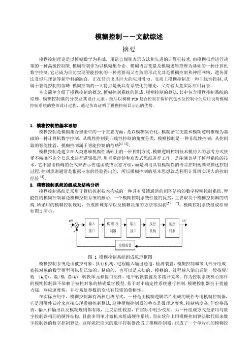
2. 模糊控制系统的组成及结构分析摸糊控制系统是采用计算机控制技术构成的一种具有反馈通道的闭环结构的数字模糊控制系统。
智能性的模糊控制器是模糊控制系统的核心,一个模糊控制系统性能的优劣,主要取决于模糊控制器的结构,所采用的模糊控制规则、合成推理算法以及模糊决策的方法等因素[6][7]。
模糊控制系统组成原理如图1所示。
伺服电机设计步骤一、确定应用需求在设计伺服电机之前,首先需要明确应用需求,包括以下几点:1. 负载类型:确定电机需要承受的负载类型,如扭矩、力、力矩等。
2. 运动方式:确定电机的运动方式,如直线、旋转等。
3. 控制精度:确定电机需要达到的控制精度。
4. 速度范围:确定电机需要承受的最大和最小速度范围。
5. 环境条件:考虑电机所处的环境条件,如温度、湿度、尘埃、振动等。
二、选择电机类型根据应用需求,选择适合的电机类型。
伺服电机通常分为以下几种类型:1. 直流伺服电机:适用于对控制精度和速度范围要求不高的应用场景。
2. 交流伺服电机:适用于对控制精度和速度范围要求较高的应用场景。
3. 步进电机:适用于对精度要求不高的应用场景,具有价格优势。
4. 直线电机:适用于直线运动控制的应用场景。
5. 旋转电机:适用于旋转运动控制的应用场景。
三、确定电机规格根据应用需求和选择的电机类型,确定电机的规格,包括以下几点:1. 功率:根据负载类型和运动方式,选择合适的电机功率。
2. 转速:根据最大和最小速度范围,选择合适的电机转速。
3. 扭矩:根据负载类型和控制精度要求,选择合适的电机扭矩。
4. 尺寸:根据安装空间和使用环境,选择合适的电机尺寸。
5. 质量:根据负载要求和使用环境,选择合适的电机质量。
6. 可靠性:考虑电机的可靠性和寿命,选择符合应用需求的电机。
7. 成本:考虑电机的成本和性价比,选择符合预算的电机。
四、设计控制系统根据应用需求和选择的电机类型及规格,设计控制系统,包括以下几点:1. 选择合适的控制器:根据应用需求和电机的控制特点,选择合适的控制器,如PLC、运动控制卡等。
2. 设计控制电路:根据控制器和电机的特点,设计控制电路,包括电源电路、速度控制电路、位置控制电路等。
3. 编写控制程序:根据控制需求,编写控制程序,实现电机的速度、位置和运动轨迹控制。
4. 调试控制程序:在实验室环境中对控制程序进行调试和优化,确保控制系统能够准确、稳定地控制电机运动。
模糊PID控制中模糊控制规则的获取方法一、概述随着工业自动化程度的不断提高,控制系统对于精确性和鲁棒性的要求也日益增强。
传统的PID控制方法虽然在实际应用中得到了广泛运用,但在处理非线性、时变以及具有不确定性的系统时,其控制效果往往不尽如人意。
模糊PID控制作为一种结合了模糊控制理论与PID控制优点的先进控制方法,逐渐受到了人们的关注。
模糊PID控制的核心在于通过模糊控制规则对PID控制器的参数进行在线调整,以适应系统特性的变化。
而模糊控制规则的获取则是实现模糊PID控制的关键步骤之一。
一个好的模糊控制规则不仅能够提高控制系统的性能,还能够降低系统的复杂度,使其更加易于实现和维护。
模糊控制规则的获取方法主要包括基于经验的方法、基于优化的方法以及基于学习的方法等。
基于经验的方法主要依赖于专家知识或实际操作经验,虽然简单易行,但往往缺乏足够的理论依据和普适性。
基于优化的方法则通过数学优化算法来寻找最优的模糊控制规则,虽然能够得到较为精确的结果,但计算复杂度较高,且对于复杂系统的优化问题可能难以求解。
而基于学习的方法则利用机器学习或深度学习等技术,通过大量数据的学习来获取模糊控制规则,这种方法具有更强的自适应性和泛化能力,但也需要足够的数据支持。
针对模糊PID控制中模糊控制规则的获取方法进行研究,具有重要的理论意义和实际应用价值。
本文旨在探讨各种模糊控制规则获取方法的优缺点及适用范围,为模糊PID控制的实际应用提供有益的参考。
1. 模糊PID控制的基本概念及特点模糊PID控制是一种结合模糊逻辑与PID控制算法的高级控制策略。
PID控制,即比例积分微分控制,是工业控制领域中应用最为广泛的控制方法之一。
传统的PID控制方法在面对复杂、非线性或时变系统时,往往难以取得理想的控制效果。
引入模糊逻辑对PID控制进行改进和优化,以提高其适应性和控制性能,成为了一种重要的研究方向。
模糊PID控制的核心思想是利用模糊逻辑对PID控制器的三个关键参数——比例系数Kp、积分系数Ki和微分系数Kd进行动态调整。
第34卷第1期2018年3月金陵科技学院学报JOURNAL OF JINLING INSTITUTE OF TECHNOLOGY Vol.34, No.1Mar.,2018DOI:10.16515/ki.32-1722/n.2018.01.0007四种智能控制方法简述张艳,杨忠,司海飞(金陵科技学院智能科学与控制工程学院,江苏南京211169)摘要:主要介绍了四种常见的智能控制方法:专家控制、模糊控制、神经网络控制和基于遗传算法的优化控制。
分别阐述了这四种智能控制方法的原理、特色、应用范围、发展现状和趋势。
关键词:智能控制;专家控制(莫糊控制(申经网络;遗传算法中图分类号:TP18 文献标识码:A文章编号"672 - 755X(2018)01 - 0029 - 04O v e rv ie w o f F o u r T ypes o f In te llig e n t C o n tro l M e th o d sZHANG Y an,YANG Zhong,SI Hai-fei(Jinling Institute of Technology,Nanjing 211169, China)Abstract:Four types of common intelligent control methods are illustrated in this paper which contain expert control,fuzzy control,neural networks control and optimal control based on genetic algorithm.Respetively,their main ideas,characteristic,applications,present situation and tendency are overviewed.Key words:intelligent control;expert control;fuzzy control;neural networks control;genetic algorithm传统的控制方法包含了经典控制理论和现代控制理论。
Design of Fuzzy Control and Expert System Based MIG Arc Welding InvertPower SourcePang QingleSchool of Information and Electronic Engineering, Shandong Institute of Business and Technology191 BinHai Road, 264005 Yantai, ChinaEmail: stefam@Abstract –Control system b ased on fuzzy and PI control for MIG welding power source is proposed, aiming at some of deficiencies in the control system based on analogous control technology and single-chip control technology, such as poor flexib ility, control precision and reliab ility. In this control system, the fuzzy control and variable parameter PI control are applied to control the arc voltage and welding current separately, and the parameters of PI controller in different welding conditions are determined b y an expert system. A digital signal controller (DSC) and a field programmable gate array (FPGA) realize fuzzy control algorithm and variab le parameter PI control algorithm separately. Finally, the hardware circuit and software flow chart of the control system are presented. The experimental results show that the control system based on fuzzy and PI control for MIG welding power source has the advantages of quicker response, etter reliability and more stable arc length.Keywords –fuzzy control; PI control; MIG welding power source; DSC; FPGA.I.INTRODUCTIONFrom 1980s, arc welding invert power source has grown through twenty years and has been current product in welding power source[1]. But the traditional control system based on analog control and single-chip control has restricted seriously the development of arc welding power source because of their deficiencies, such as poor flexibility, control precision and reliability[2]. With the development of E DA technology and digital signal processing technology, the digital control system becomes reality. Many domestic and foreign researcher has studied the control system of MIG welding invert power source and obtained many research results, such as Japanese Panasonic company produces digital welding machine ˉ YC-300BZ2 and YD-350GB1 based on 64 bit CPU, Austrian company produces TPS series welding machine, and German CLOOS company produces MIG/MAG welding machine[3,4]. Our country's digitized power source research starts late, mainly concentrates in several research institutes and universities, like Beijing Industrial University[5], Shanghai Jiaotong University[6], Huanan University of Science and Technology[7], Lanzhou University of Science and Technology[8] and so on. In order to further improve the welding quality and satisfy real-time and the control precision which the MIG welding power source digital control needs, the digital control system of MIG welding power source based on DSC and the FPGA is proposed by using fuzzy control and variable parameter PI control.II.CONTROL ALGORITHM OF MIG WELDING POWER SOURCE CONTROL SYSTEMA.Structure of control systemThe control system block diagram is given in Figure 1. The system is composed of three main parts: the current waveform control system, the arc length control system and expert control system. The current waveform control system and the arc length control system all use the closed-loop controller. These two closed-loop controller construct dual closed-loop control system, the current waveform control is the inner loop control and the arc length control is the outer loop control. And the expert system is the adjustor of the dual closed-loop controlFigure 1. Frame of MIG welding control systemB.Current waveform controller based on variableparameter PI controlIn order to realize the welding stable control, the current loop should be a constant current source. The current control approach is usually the PI algorithm. The proportional controller is used to reach a good dynamic response performance and the integral controller is used to overcome static error, increase control precision and obtain a good control effect. By analyzing the droplet transfer behavior, a cycle of the droplet transfer process is divided into four stages. The current waveform presents different characteristic in different stage and the current waveform is showed in Figure 2, where 1 denotes the rise stage, 2 denotes the peak stage, 3 denotes the drop stage and 4 denotes the base stage. To satisfy the_____________________________ 978-1-4244-3864-8/09/$25.00 ©2009 IEEEdemand in different stage of welding current, the variable parameter PI control is adopted. In these controllers, the different proportion and integral parameters are used in different stages. When the welding wire material, shielded gas, welding wire diameter or wire feed speed varies, the proportion and integral parameters in the fourstages are regulated by the expert system.Figure 2. Sketch map of current waveform controlC. Fuzzy control based arc controllerBecause of the arc control system is usually a nonlinear system, the arc control system uses fuzzy controller. To ensure arc length stability in welding process and reach “one droplet per pulse”, the base value time is regarded as controlling variable and the arc average voltage as controlled variable. Then the fuzzy controller is designed.The inputs of the fuzzy controller are defined as ¯® 1n n nfng n e e ec U U e (1) where e n denotes the n th sample error, U g denotes the reference voltage value, ec n denotes the n th change-in-error and e n -1 denotes the n -1th sample error. The arc length fluctuation should not exceed 5mm. The electric-field strength in shielded gas environment is 0.59V/mm. So the variation range of the input e n isV V e n 3~359.0)5(~59.0)5( |u u (2) The experiments show that the range of the base value time is 3~15ms to ensure welding process stability and little splash. So when the mean arc voltage changes 1V , the corresponding base value time changes ms 2)3(3315 . If the range of the peak voltage is r 3V ,the change range of base value time is r 6ms , that is, [-6, 6]. The fuzzy variables corresponding to the inputs e n , ec nand T b are E , EC and T respectively. The domains of Eand EC are all set by [-3, 3], that is, E =EC ={-3,-2,-1,0,1,2,3}. The domain of T is set by [-6,6], that is, T ={-6,-5,-4,-3,-2,-1,0,1,2,3,4,5,6}}. The domains of E , EC and T are all divided into sevendegrade: PL(poslarge), PM(posmiddle), PS(possmall),Z(zero), NS(negsmall), NM(negmiddle) andNL(neglarge). Both input and output adopt triangularmembership function and these triangular membershipfunctions are showed as Figure 3 and Figure 4. Thequantification factors of the error E and thechange-in-error EC are set by k e =k ec =2, the proportionfactor of the output T is set by k T=1.NB NM NS ZO PS PM PB C h a n g -i n -e r r o r E CNB PB PB PM PM ZO ZO ZO NMPBPMPM PS PS NSNSNS PB PM PS PS ZO NM NB ZO PB PM PS ZO NS NM NBPS PM PS ZO NS NS NM NB PM PS PS NS NM NM NM NB PB ZO ZO NS NM NM NB NBIII. HARDWARE DESIGN OF MIG WELDING POWER SOURCE A. Hardware structure of welding power source Usually the MIG welding power source is composed of four parts: main circuit, control system circuit, human machine interface and wire feeder. The structure frame is showed as Figure 5. The theory and technology of maincircuit and wire feeder have been developed and needn’t design again. The paper focuses on the control system. The hardware of the control system includes: current loop control system, voltage loop control system and peripheral circuit. The current loop control system includes the FPGA system, the welding current shaping and amplifying circuit, the A/D converter circuit and the D/A converter circuit. Their main role is to produce the current waveform and realize digital PI control algorithm. The voltage loop control system includes DSC system and arc voltage shaping and amplifying circuit. Their main role is to realize fuzzy control algorithm and data storage and parameter transfer of the expert system. The peripheral circuit includes digital I/O circuit, communication circuit and so on. The control system isshowed as the dashed line frame of Figure 5.Figure 6. Software flow chart of control systemIV. SOFTWARE DESIGN OF MIG WELDINGSOURCE In the control system, DSC is main controller torealize fuzzy control algorithm and expert system. FPGA is coprocessor to accomplish A/D control, D/A control and hardware PID algorithm by using VHDL language.The software flow chart of MIG welding power source control system is showed as Figure 6. After program initialization and permitting welding, the arc ignition subprogram starts, including sequential control (gas feeding, wire feeding and so on) and arc ignition. When the welding current exceeds the given value, after a cycle of time delay the program turns into the circulation of the base value and the peak value. In base period, the base current PI control is executed and when the base value time arrives at the setting value or the mean arc voltage is less than the setting threshold value the program turns into the rise period. In the rise period, the current PI control is executed and when the rise time arrives at the setting value the program turns into the peak period. In the peak period, the peak current PI control is executed. After 1ms, the mean arc voltage is calculated and when the peak value time arrives at the setting value or the mean arc voltage is more than the setting threshold value the program turns into the drop period. In the drop period, the current PI control is executed and when the drop time arrives at the setting value the program turns into the base period. In these 4 periods, PI parameters change with welding material and shielding gas. These parameters are provided by the expert system. In the pulse cyclic process, the program inspects the welding stop signal continually, once the stopping welding instruction is received, the procedure enters the arc extinction control stage. Finally, the system stops welding and waits new welding switch signals.V.EXPERIMENT RESULTThe welding experiment is done under the condition that the shielding gas is argon, the setting current is 130A and the mean voltage is 24V. The waveform of the welding current and voltage are showed as Figure 7, where the voltage waveform is in channel 3 and the current waveform is in channel 2. In Figure 7, the voltage waveform 0.5V denotes the actual welding voltage 10V and the current waveform 2V denotes the actual welding current 100A. From the figure, we can see that the base value voltage is 18V, the peak voltage is 32V, the base value current is 50A, the peak time is 1.5ms and the base value time 3.5ms. All these values are consistent with the setting values. The photo of actual weld shape is showed as Figure.8. In the welding process, the droplet transfer process is stable and the splash is slight.VI.CONCLUSIONIn order to meet the real-time of the welding power source and improve control precision, the control system based on DSC and FPGA for MIG welding power source is presented. In the system, FPGA executes variable parameter PI control to meet the real-time control and make the welding stability. DSC realizes the fuzzy control and the expert system algorithm to realize arc voltage accurate control. The experiment results show that the system has fast dynamic response, high reliability, stable arc length control and good welding quality.Figure 7. Waveform of voltage and currentFigure 8. Photo of welding shapeACKNOWLEDGMENTThis project is supported by National Natural Science Fund(60673153) and Natural Science Foundation of Shandong Province (Z2006F05).REFERENCES[1]H. Yamamoto, S. Harada, T. Ueyama. “Improved current controlmakes inverters the power sources of choice”, Welding Journal,1997, vol.76, no.2, pp: 47-49.[2]Huang Shisheng. Arc welding power source and digital controlsystem, Beijing: China Machine Press, 2006.[3]Wu Kaiyuan, Lu Peitao, Li Yang, et al. “Situation andexpectation on pulsed MIG welding control technique”, ElectricWelding Machine, 2003, vol.33, no.2, pp: 1-4.[4]Li Feng, Li Liangyu, Li Xiang. “Internal research status of digitalelectric welding machine”, Welding Technology, 2006, vol. 35, no. 4, pp: 6-8.[5]Liao Ping, Huang Pengfei, Lu Zhenyang, et al. “Variable polaritypulsed metal inert-gas control system”, Transactions of the ChinaWelding Institution, 2006, vol.27, no.3, pp: 53-56.[6]Bao Yefeng, Zhou Yun, Wu Yixiong, et al. “Aluminum alloyspulsed MIG based on dynamic characteristics self-adaptation control”, Journal of Shanghai Jiaotong University, 2004, vol. 38,no. 7, pp: 1126-1129,1133.[7]Wu Kaiyuan, Huang Shisheng, Meng Yongmin. “Double-modelfuzzy logic control strategy of arc in pulsed metal inertia gas welding”, Control Theory & Applications, 2006, vol. 23, no.1, pp:74-78.[8]Shi Yu, Xue Cheng, Fan Ding, et a l. “Modeling and simulation ofdecoupling control system of aluminum pulsed MIG welding”, Transactions of the China Welding Institution, 2008, vol.29, no.5,pp: 9-12.。
智能控制基础答案【篇一:智能控制基础思考题】xt>复习思考题一重要概念解释 1 智能控制答:智能控制是一门交叉学科,美国学者在运筹学的基础上提出了三元论的智能控制概念,即ic=ac n ai n or 各子集的含义为:ic为智能控制,ai为人工智能,ac为自动控制,or为运筹学。
所谓智能控制,即设计一个控制器,使之具有学习、抽象、推理、决策等功能,并能根据环境(包含被控对象或被控过程)信息的变化做出适应性反应,从而实现由人来完成的任务。
2 专家系统与专家控制答:专家系统是一类包含知识和推理的智能计算机程序,其内部包含某领域专家水平的知识和经验,具有解决专门问题的能力。
专家控制是智能控制的一个重要分支,又称专家智能控制。
所谓专家控制,是将专家系统的理论和技术同控制理论、方法与技术相结合,在未知环境下,仿效专家的经验,实现对系统的控制。
3 模糊集合与模糊关系,模糊推理模糊控制答:模糊集合:给定论域u上的一个模糊集a?是指:对任何元素u?u 都存在一个数?a?u???0,1?与之对应,表示元素u属于集合a?的程度,这个数称为元素u对集合a?的隶属度,这个集合称为模糊集合。
模糊关系:二元模糊关系:设a、b是两个非空集合,则直积a?b???a,b?|a?a,b?b?中的一个模糊集合称为从a到b的一个模糊关系。
模糊关系r?可由其隶属度?r?a,b?完全描述,隶属度?r?a,b?表明了元素a与元素b具有关系r?的程度。
模糊推理:知道了语言控制规则中蕴含的模糊关系后,就可以根据模糊关系和输入情况,来确定输出的情况,这就叫“模糊推理”。
4神经网络?答:人工神经网络(artificial neural network )是模拟人脑思维方式的数学模型。
神经网络是在现代生物学研究人脑组织成果的基础上提出的,用来模拟人类大脑神经网络的结构和行为,它从微观结构和功能上对人脑进行抽象和简化,神经网络反映了人脑功能的基本特征,如并行信息处理、学习、联想、模式分类、记忆等。
模糊控制规则表什么是模糊控制规则表模糊控制规则表是模糊控制系统中的关键组成部分之一。
它定义了输入变量和输出变量之间的模糊关系,并通过一系列规则来描述输入和输出之间的映射关系。
模糊控制规则表的设计和优化对于模糊控制系统的性能至关重要。
模糊控制规则表的结构模糊控制规则表由多个规则组成,每个规则包含一个条件部分和一个结论部分。
条件部分用于描述输入变量的模糊集合,结论部分用于描述输出变量的模糊集合。
模糊控制规则表的结构可以用以下形式表示:IF <条件1> AND <条件2> AND ... THEN <结论>其中,条件和结论可以使用模糊集合的标签或模糊数值表示。
模糊控制规则表的设计方法模糊控制规则表的设计方法可以分为基于经验和基于模型两种。
基于经验的设计方法基于经验的设计方法是通过专家的经验和直觉来确定模糊控制规则表的内容。
专家可以根据自己的知识和经验,提供一些规则,并根据系统的响应进行调整和优化。
这种方法的优点是简单易行,但缺点是需要依赖专家的经验,且无法保证获得最优的控制效果。
基于模型的设计方法基于模型的设计方法是通过数学模型和系统辨识技术来确定模糊控制规则表的内容。
首先需要建立系统的数学模型,然后通过系统辨识技术从实验数据中提取模型的参数。
接下来,可以使用模型来生成一些基本规则,并根据系统的性能指标进行优化。
这种方法的优点是可以自动化地生成规则,并且可以通过优化算法来获得最优的控制效果。
模糊控制规则表的优化方法模糊控制规则表的优化方法可以分为两类:规则剪裁和规则生成。
规则剪裁规则剪裁是指通过删除一些不必要或冗余的规则来简化规则表。
可以使用以下方法进行规则剪裁:1.删除冲突规则:如果存在两个规则的条件部分完全相同,但结论部分不同,则可以删除其中一个规则。
2.删除冗余规则:如果存在一个规则的条件部分可以被其他规则的条件部分包含,则可以删除这个规则。
3.合并相似规则:如果存在多个规则的条件部分相似,但结论部分不同,则可以合并这些规则。
模糊控制概述模糊控制是一种基于模糊逻辑的控制方法,它允许系统根据不确定或模糊的输入和输出进行决策和控制。
与传统的确定性控制方法相比,模糊控制更适用于处理复杂、非线性和模糊的系统。
模糊控制的核心思想是将模糊逻辑应用于控制系统的设计和实现中。
传统的控制方法通常基于准确的数学模型和精确的输入输出关系,然而,在现实世界中,许多系统往往难以精确地建模和描述。
模糊控制通过模糊化输入和输出,以及使用模糊规则进行推理和决策,能够更好地应对这种不确定性和模糊性。
模糊控制系统一般由四个基本部分组成:模糊化模块、模糊规则库、推理引擎和解模糊化模块。
模糊化模块将输入量转化为模糊集,模糊规则库存储了一系列模糊规则,推理引擎利用这些规则进行推理和决策,解模糊化模块将模糊输出转化为确定性的控制量。
在模糊控制中,模糊集合和模糊关系是核心概念。
模糊集合是指具有模糊边界和隶属度函数的集合,用来表示不确定性或模糊性。
模糊关系是指模糊集合之间的关系,它可以通过模糊规则来描述。
模糊规则是一种条件-动作规则,它基于模糊关系,将模糊输入映射到模糊输出。
模糊控制的关键是如何构建模糊规则库。
通常,模糊规则库是由领域专家通过经验和知识来构建的。
这些规则通常采用人类语言来描述,例如:“如果温度高且湿度低,则增大空调的制冷量”。
在实际应用中,可以通过模糊规则的学习和优化来改进模糊控制系统的性能。
模糊控制在许多领域都有广泛的应用。
例如,在自动化控制中,模糊控制可以用于控制温度、湿度、速度等参数;在交通控制中,模糊控制可以用于调整红绿灯的时序和间隔;在机器人控制中,模糊控制可以用于路径规划和动作决策等。
尽管模糊控制具有一定的优势,但也存在一些局限性。
首先,模糊控制通常需要大量的模糊规则,这对于复杂系统而言可能是不可行的。
其次,模糊控制的系统性能高度依赖于模糊规则的质量和数量,因此模糊规则的构建和优化是一个复杂且困难的任务。
此外,由于模糊控制系统的非线性特性,对于大规模和高维度的系统,模糊控制可能会面临计算复杂度和实时性的挑战。