STC温控表使用说明书
- 格式:docx
- 大小:647.23 KB
- 文档页数:2
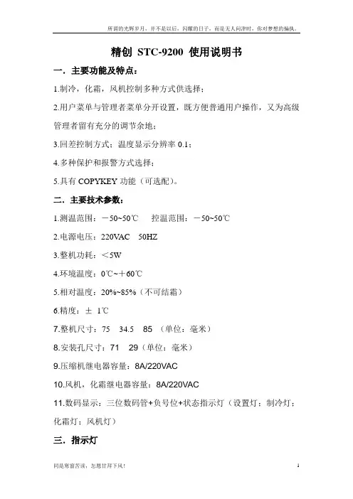
精创STC-9200 使用说明书一.主要功能及特点:1.制冷,化霜,风机控制多种方式供选择;2.用户菜单与管理者菜单分开设置,既方便普通用户操作,又为高级管理者留有充分的调节余地;3.回差控制方式;温度显示分辨率0.1;4.多种保护和报警方式选择;5.具有COPYKEY功能(可选配)。
二.主要技术参数:1.测温范围:-50~50℃控温范围:-50~50℃2.电源电压:220VAC 50HZ3.整机功耗:<5W4.环境温度:0℃~+60℃5.相对温度:20%~85%(不可结霜)6.精度:±1℃7.整机尺寸:75 ×34.5 ×85 (单位:毫米)8.安装孔尺寸:71 ×29(单位:毫米)9.压缩机继电器容量:8A/220VAC10.风机,化霜继电器容量:8A/220VAC11.数码显示:三位数码管+负号位+状态指示灯(设置灯;制冷灯;化霜灯;风机灯)三.指示灯四.按键功能及设置方式:五.参数项清单六.功能介绍:1.压缩机;A.电热化霜状态下,风机延时设置为正:启动条件;当满足条件a) . b) 或者满足条件a) . c) 时,压缩机继电器吸合。
a)压缩机延时超过设定的延时时间。
b)库温高于设置温度,强制制冷开始。
c)非化霜状态下,库温高于设置温度+回差设置值(当风机延时为负值时,在满足其他启动条件且压机已经运行完延时数值的绝对值后压缩机继电器吸合)关闭条件:满足以下条件之一,压缩机继电器断开◇库温低于设置温度◇化霜开始时◇强制制冷结束B.热气化霜状态下:启动条件;当满足条件a) . b) 或者满足条件a) . c) 或者a) . d)时,压缩机继电器吸合。
a)压缩机延时超过设定的延时时间。
b) 非化霜状态下,库温高于设置温度+回差设置值c)库温高于设定温度强制制冷开始。
d)化霜时(当风机延时为负值时,在满足其他启动条件且压机已经运行完设定的延时数值的绝对值后压缩机继电器吸合。
温控仪使用说明书一、引言温控仪是一种用于控制温度的装置,能够实时监测环境温度并进行相应的控制。
本使用说明书旨在帮助用户正确使用温控仪,并了解其相关功能和操作方式。
二、产品概述温控仪是一款智能温度控制设备,具有以下特点:1. 高精度:温控仪采用先进的温度传感器,能够实时准确地测量环境温度。
2. 安全可靠:温控仪配备多重安全保护机制,如温度过高自动断电、电流过载保护等,确保使用过程中的安全。
3. 易操作:温控仪采用人性化设计,具有简单易懂的操作界面,方便用户快速上手使用。
4. 多功能:温控仪不仅可以控制环境温度,还能进行定时开关、温度调整等功能。
三、产品外观及配件1. 外观:温控仪外形简洁、美观,采用优质材料制作,手感舒适。
2. 屏幕:温控仪配备高清LCD屏幕,能够清晰显示当前温度和设置参数。
3. 按钮:温控仪设有几个简单易用的按钮,用于切换菜单和进行参数设置。
4. 电源线:温控仪附带一根标准电源线,用于连接电源。
5. 说明书:本产品配有一本详细的使用说明书,用于指导用户正确操作温控仪。
四、使用方法1. 连接电源:将温控仪的电源线插入电源插座,并确保电源开关处于关闭状态。
2. 开机:按下电源开关,温控仪将进入开机状态,屏幕上将显示当前室内温度。
3. 菜单切换:按下菜单切换按钮,可以切换不同的功能菜单。
4. 参数设置:在相应的菜单中,使用上下左右按钮选择需要设置的参数,然后按下确认按钮进行设置。
5. 温度调整:在温度调整菜单中,使用上下按钮可以调整所需的目标温度,再次按下确认按钮即可保存设置。
6. 定时功能:如果需要定时开关温控仪,可以进入定时设置菜单,按照屏幕提示进行相应设置。
7. 关机:长按电源开关,温控仪将进入关机状态,同时断开电源。
五、注意事项1. 请勿将温控仪暴露在潮湿、高温、高压、腐蚀性环境中。
2. 使用前,请先阅读本使用说明书,并按照操作指南正确操作。
3. 请避免温控仪受到冲击、摔落或挤压,以免损坏。
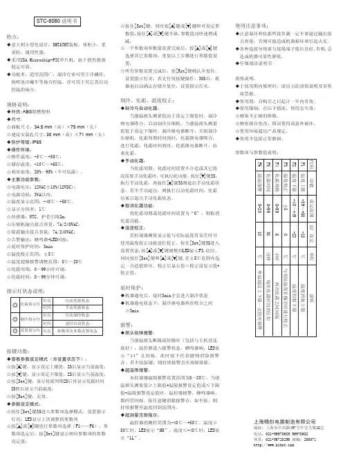
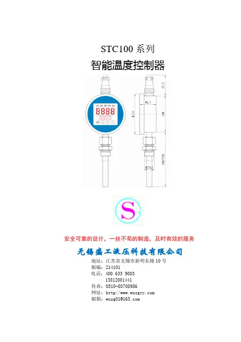
特点:◆意大利小型化设计,SMT&THT装配,体积小,重 量轻,通用性强。
◆采用USA Microchip-PIC单片机,抗干扰性能强 稳定可靠。
◆功能多,适用范围广,制冷行业可用于冷藏库, 海鲜池冷藏车等场合控温,亦可用于其它需自动 控温的场合。
规格说明:◆外壳:ABS 阻燃塑料◆尺寸:☆面板尺寸:34.5 mm (高)×75 mm (长)☆建议安装孔尺寸:30 mm (高)×71 mm (长)◆防护等级:IP65◆操作环境:☆操作温度:-5℃~+55℃;☆储存温度:-10℃~+65℃;☆相对湿度:20%~95%(不可结露)。
◆主要功能参数:☆电源电压:12VAC±10%(12VDC);☆电源功耗:3VA以内;☆温度显示范围:-40℃~+50℃,☆显示分辩率:1℃☆传感器:NTC,护套引线2m;☆压缩机输出接点容量:7A/240VAC;☆除霜输出接点容量:7A/240VAC;☆告警输出:蜂鸣器+LED闪烁;☆延时保护时间:3min☆温度校正范围:±5℃☆温度超限报警调整范围:0℃~20℃☆化霜周期:0~99小时可调;☆化霜时间:0~99分钟可调;指示灯状态说明:按键功能:◆查看参数设定模式(非设置状态下):☆按[ ]键,显示设定上限值,2S后显示当前温度;☆按[ ]键,显示设定下限值,2S后显示当前温度;☆按[Set]键,显示化霜周期2S后再显示化霜时间 2S然后显示当前温度;☆按[Rst]键,无效。
◆参数设定模式:☆按住[Set]键3S进入参数项选择模式,设置指示 灯亮;LED显示上次调整的参数项☆按[ ]或[ ]键进行参数项选择(F1……F6),参 数项选定后,按[Set]键显示相应参数项的参数 设定值;化霜指示灯制冷指示灯设置指示灯红亮 自动化霜状态红闪 手动化霜状态红亮 自动制冷状态红闪 延时启动状态红亮 参数项及参数设置状态 ☆按住[Set]键,同时按[ ]键或[ ]键即可设定参 数值,按住[ ]或[ ]键不放,参数值动快速增或 减;☆一个参数项参数值设置完成后,按[ ]或[ ]键 选择其它参数项,重复以上步骤进行参数值设 置;☆所有参数设置完成后,按[Rst]键确认并复位, 设置指示灯灭。

STC-A型冲击电压试验仪说明书郑州博天电子技术有限公司一、概述STC-A型冲击电压试验仪是根据TB/T 2653-2003、GB/T 17627.1-1997、GB/T14048-2000、GB7251、GB/T16927.1-1997、GB3048、GB4706、IEC 61730-2005等标准要求,用于防雷变压器、太阳能、低压成套、低压电器、电度表、电机、电线电缆、漏电保护器等产品安全性能检测的冲击电压试验仪器,是低压成套、电线电缆企业的“3C”认证出厂检验设备。
设备采用高速单片机设计,液晶显示,触摸按键设计,中英文操作菜单,具有操作方便、性能稳定可靠、自动化程度高的优点。
二、原理简介2.1 结构组成原理结构框图如下:图1原理框图2.2 原理描述仪器以高速单片机为核心,通过液晶显示及触摸按键构成人机交互系统,通过中英文操作菜单设置相关参数,单片机根据参数设置控制高压发生器输出电压,根据设置的时间间隔控制点火装置,经过阻容网络输出高压脉冲。
16三、技术参数及特性3.1 输出电压输出直流:0-16KV;精度3%FS±1个字;冲击峰值:0-12KV;精度3%FS±1个字;3.2 冲击电压波波前时间 1.2μs±30%;波后半值时间 50μs±20%;3.3 输出方式冲击次数 0-99次及连续输出设定;间隔时间 0-99s;3.4 电源条件额定电压 AC220V±10%,50Hz;额定功耗 150VA。
3.6 环境条件环境温度 0-40℃环境湿度不大于80%。
3.7 外形尺寸450mm*422mm*220mm;四、仪器的面板介绍4.1 前面板1-液晶显示窗口;2-功能按键区;3-电压调整旋钮;4-直流电压输出接口;5-冲击电压输出接口;6-GND;图2 :冲击电压试验仪前面板示意图4.2 后面板图3 :冲击电压试验仪后面板示意图1-电源输入端口;2-GND;3-电源开关;4-电压测试端口。
精创STC-9200 使用说明书一.主要功能及特点:1.制冷,化霜,风机控制多种方式供选择;2.用户菜单与管理者菜单分开设置,既方便普通用户操作,又为高级管理者留有充分的调节余地;3.回差控制方式;温度显示分辨率0.1;4.多种保护和报警方式选择;5.具有COPYKEY功能(可选配)。
二.主要技术参数:1.测温范围:-50~50℃控温范围:-50~50℃2.电源电压:220VAC 50HZ3.整机功耗:<5W4.环境温度:0℃~+60℃5.相对温度:20%~85%(不可结霜)6.精度:±1℃7.整机尺寸:75 × 34.5 × 85 (单位:毫米)8.安装孔尺寸:71 × 29(单位:毫米)9.压缩机继电器容量:8A/220VAC10.风机,化霜继电器容量:8A/220VAC11.数码显示:三位数码管+负号位+状态指示灯(设置灯;制冷灯;化霜灯;风机灯)三.指示灯四.按键功能及设置方式:五.参数项清单六.功能介绍:1.压缩机;A.电热化霜状态下,风机延时设置为正:启动条件;当满足条件a) . b) 或者满足条件a) . c) 时,压缩机继电器吸合。
a)压缩机延时超过设定的延时时间。
b)库温高于设置温度,强制制冷开始。
c)非化霜状态下,库温高于设置温度+回差设置值(当风机延时为负值时,在满足其他启动条件且压机已经运行完延时数值的绝对值后压缩机继电器吸合)关闭条件:满足以下条件之一,压缩机继电器断开◇库温低于设置温度◇化霜开始时◇强制制冷结束B.热气化霜状态下:启动条件;当满足条件a) . b) 或者满足条件a) . c) 或者a) . d)时,压缩机继电器吸合。
a)压缩机延时超过设定的延时时间。
b) 非化霜状态下,库温高于设置温度+回差设置值c)库温高于设定温度强制制冷开始。
d)化霜时(当风机延时为负值时,在满足其他启动条件且压机已经运行完设定的延时数值的绝对值后压缩机继电器吸合。
温控设备使用方法说明书一、产品概述本设备是一种用于控制温度的电子设备,适用于各种需要温度控制的场合。
该设备具有精度高、操作简便等特点,可广泛应用于工业生产、实验室等领域。
二、产品特性1. 精确控制:本设备采用高精度的温度传感器和控制芯片,能够实时感知环境温度,并根据设定的参数实现精准控制。
2. 多功能显示:设备面板配备液晶屏幕,能够显示当前温度、设定温度以及操作状态和故障码等信息。
3. 安全可靠:设备具备过温保护功能,在温度超过设定范围时会自动切断电源,确保设备和环境的安全。
4. 高效节能:设备采用先进的节能技术,在达到设定温度后能够自动切换到低功耗模式,保证节能效果。
5. 多种控制模式:本设备支持多种控制模式,可根据实际需求选择恒温、程序、循环等模式。
三、产品使用说明1. 设备安装:将本设备放置在平坦的表面上,确保通风良好,不与其他热源或易燃物接触。
保持周围环境清洁,避免尘埃或异物进入设备内部。
2. 设备连接:将电源线插入交流电源插座,并确保电源电压与设备要求相符。
设备须连接地线以确保安全。
3. 设备开机:将电源开关打开,设备将进入待机状态。
此时,液晶显示屏会显示当前室温。
4. 设备设置:按照设备使用场合的需要,通过屏幕上的按键进行参数设置。
根据具体说明书的内容,选择控制模式、设定温度、运行时间等参数。
5. 设备运行:确认参数设置无误后,按下启动键,设备将开始工作,并根据设定的温度进行自动控制。
6. 设备维护:定期清洁设备表面和内部,避免灰尘和杂质影响设备性能。
如发现设备出现故障,请及时断电并联系维修人员处理。
四、注意事项1. 请勿将设备长时间暴露在高温、潮湿或有腐蚀性气体的环境中,以免损坏设备。
2. 设备应放置在儿童无法触及的地方,以防不慎操作或触碰设备。
3. 设备故障时,请勿擅自拆卸修理,应联系售后服务中心或专业维修人员进行处理。
4. 设备在长时间不使用时,应断开电源并妥善保存,以延长设备寿命。
安全措施1.对安装或维修人员的技能要求①具有从事CCTV系统安装或维修的资格证书。
②具有从事高空作业的资格证书。
③具有低压布线和低压电子线路接线的基础知识和操作技能。
④了解并熟悉本产品使用说明。
2.对升降设备的要求①使用适合安装地点和球机安装方式的安全升降设备。
②升降设备具有到达安装位置的足够的举升高度。
③升降设备具有良好的安全性能。
注意事项1.小心运输运输及保管过程中要防止重压、剧烈振动和浸泡等对产品造成的损坏。
本产品必须采用分体包装形式运输,无论工程商发货还是返回工厂维修,若因未采用安全包装而运输,造成的任何产品损坏,不属保修范围。
2.发生故障时如果本机出现冒烟、异常气味或功能不正常,应立即关闭电源并断开电源线,停止使用本机,然后与制造商联系。
3.切勿拆开或改装切勿打开壳体,否则可能会导致危险或引起本机损坏。
如果进行内部设定或维修,请与制造商联系。
4.切勿把别的物品放入本机确认摄像机内没有金属物或易燃物。
如果机内有异物,可能会引起着火、短路或损伤。
如果水或液体流入摄像机,请立即关闭电源并断开电源线,然后与制造商商谈。
小心地保护摄像机,避免雨水、海水侵蚀。
5.小心提放本机为了避免损伤,切勿使摄像机掉落或遭受强烈的震动或冲击。
6.设置在远离电场和磁场的场所如果设置在电视机、无线电发射机、电磁装置、变压器、扬声器附近,它们产生的电磁场将会干扰图像。
7.避免湿气和灰尘为了避免摄像机损坏,切勿把摄像机设置在有油烟或水蒸气、温度过高或有很多灰尘的场所。
8.避免高温切勿设置在取暖炉或其他热源的附近,如聚光灯。
也不要设置在易受阳光照射的地方,否则会引起摄像机的变形、褪色或其他损伤。
当设置在天花板、厨房或锅炉房附近时,温度可能会升得很高。
9.清洁用软布擦拭能去掉壳体上的脏物。
要除去污垢,可用软布沾上洗涤剂溶液并拧干后擦拭,然后再用干的软布擦干。
切勿使用汽油、涂料稀释剂或其他化学品清洁壳体,否则可能会引起变形和涂漆剥落。
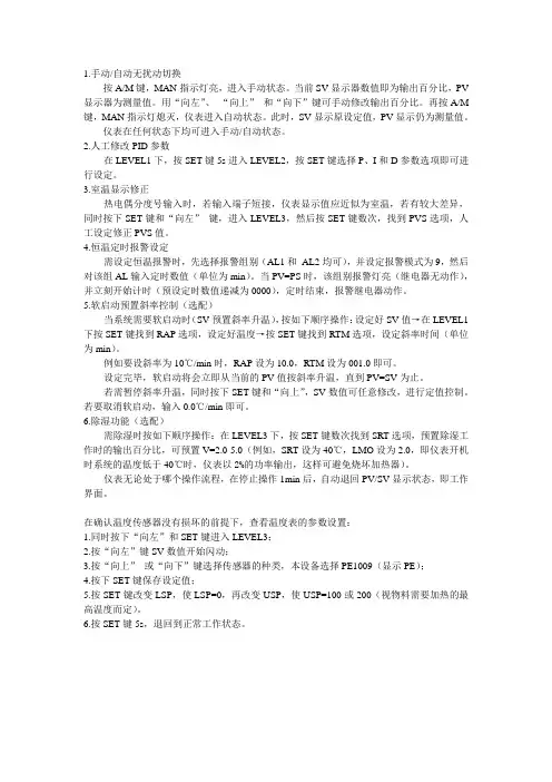
1.手动/自动无扰动切换按A/M键,MAN指示灯亮,进入手动状态。
当前SV显示器数值即为输出百分比,PV 显示器为测量值。
用“向左”、“向上”和“向下”键可手动修改输出百分比。
再按A/M 键,MAN指示灯熄灭,仪表进入自动状态。
此时,SV显示原设定值,PV显示仍为测量值。
仪表在任何状态下均可进入手动/自动状态。
2.人工修改PID参数在LEVEL1下,按SET键5s进入LEVEL2,按SET键选择P、I和D参数选项即可进行设定。
3.室温显示修正热电偶分度号输入时,若输入端子短接,仪表显示值应近似为室温,若有较大差异,同时按下SET键和“向左”键,进入LEVEL3,然后按SET键数次,找到PVS选项,人工设定修正PVS值。
4.恒温定时报警设定需设定恒温报警时,先选择报警组别(AL1和AL2均可),并设定报警模式为9,然后对该组AL输入定时数值(单位为min)。
当PV=PS时,该组别报警灯亮(继电器无动作),并立刻开始计时(预设定时数值递减为0000),定时结束,报警继电器动作。
5.软启动预置斜率控制(选配)当系统需要软启动时(SV预置斜率升温),按如下顺序操作:设定好SV值→在LEVEL1下按SET键找到RAP选项,设定好温度→按SET键找到RTM选项,设定斜率时间(单位为min)。
例如要设斜率为10℃/min时,RAP设为10.0,RTM设为001.0即可。
设定完毕,软启动将会立即从当前的PV值按斜率升温,直到PV=SV为止。
若需暂停斜率升温,同时按下SET键和“向上”,SV数值可任意修改,进行定值控制。
若要取消软启动,输入0.0℃/min即可。
6.除湿功能(选配)需除湿时按如下顺序操作:在LEVEL3下,按SET键数次找到SRT选项,预置除湿工作时的输出百分比,可预置V=2.0-5.0(例如,SRT设为40℃,LMO设为2.0,即仪表开机时系统的温度低于40℃时,仪表以2%的功率输出,这样可避免烧坏加热器)。
STC功能说明书STC-ISP Ver6.38下载软件功能说明书目录●发布项目程序使用说明 (3)●自定义加密下载使用说明 (7)●发布项目程序+ 自定义加密下载结合使用说明 (11)●用户自定义下载说明 (17)●RS485控制使用说明 (18)●STC仿真器使用指南 (20)●用户自制脱机下载板/U7 全自动烧录工具注意事项 (24)发布项目程序使用说明发布项目程序功能主要是将用户的程序代码与相关的选项设置打包成为一个可以直接对目标芯片进行下载编程的超级简单的用户自己界面的可执行文件。
关于界面,用户可以自己进行定制(用户可以自行修改发布项目程序的标题、按钮名称以及帮助信息),同时用户还可以指定目标电脑的硬盘号和目标芯片的ID号,指定目标电脑的硬盘号后,便可以控制发布应用程序只能在指定的电脑上运行(防止烧录人员将程序轻易从电脑盗走,如通过网络发走,如通过U盘烤走,防不胜防,当然盗走你的电脑那就没办法那,所以STC的脱机下载工具比电脑烧录安全,能限制可烧录芯片数量,让前台文员小姐烧,让老板娘烧都可以),拷贝到其它电脑,应用程序不能运行。
同样的,当指定了目标芯片的ID号后,那么用户代码只能下载到具有相应ID号的目标芯片中(对于一台设备要卖几千万的产品特别有用---坦克,可以发给客户自己升级,不需冒着生命危险跑到战火纷飞的伊拉克升级软件啦),对于ID号不一致的其它芯片,不能进行下载编程。
发布项目程序详细的操作步骤如下:1、首先选择目标芯片的型号2、打开程序代码文件3、设置好相应的硬件选项4、试烧一下芯片,并记下目标芯片的ID号,如下图所示,该芯片的ID号即为“000D001100641D”(如不需要对目标芯片的ID号进行校验,可跳过此步)5、设置自动增量(如不需要自动增量,可跳过此步)6、设置RS485控制信息(如不需要RS485控制,可跳过此步)7、设置用户自定义下载命令(如不需要此功能,可跳过此步)8、点击界面上的“读取本机硬盘号”按钮,并记下目标电脑的硬盘号(如不需要对目标电脑的硬盘号进行校验,可跳过此步)9、点击“发布项目程序”按钮,进入发布应用程序的设置界面。
精创STC-9200 使用说明书一.主要功能及特点:1.制冷,化霜,风机控制多种方式供选择;2.用户菜单与管理者菜单分开设置,既方便普通用户操作,又为高级管理者留有充分的调节余地;3.回差控制方式;温度显示分辨率0.1;4.多种保护和报警方式选择;5.具有COPYKEY功能(可选配)。
二.主要技术参数:1.测温范围:-50~50℃控温范围:-50~50℃2.电源电压:220V AC 50HZ3.整机功耗:<5W4.环境温度:0℃~+60℃5.相对温度:20%~85%(不可结霜)6.精度:±1℃7.整机尺寸:75 ×34.5 × 85 (单位:毫米)8.安装孔尺寸:71 × 29(单位:毫米)9.压缩机继电器容量:8A/220VAC10.风机,化霜继电器容量:8A/220VAC11.数码显示:三位数码管+负号位+状态指示灯(设置灯;制冷灯;化霜灯;风机灯)三.指示灯四.按键功能及设置方式:五.参数项清单六.功能介绍:1.压缩机;A.电热化霜状态下,风机延时设置为正:启动条件;当满足条件a) . b) 或者满足条件a) . c) 时,压缩机继电器吸合。
a)压缩机延时超过设定的延时时间。
b)库温高于设置温度,强制制冷开始。
c)非化霜状态下,库温高于设置温度+回差设置值(当风机延时为负值时,在满足其他启动条件且压机已经运行完延时数值的绝对值后压缩机继电器吸合)关闭条件:满足以下条件之一,压缩机继电器断开◇库温低于设置温度◇化霜开始时◇强制制冷结束B.热气化霜状态下:启动条件;当满足条件a) . b) 或者满足条件a) . c) 或者a) . d)时,压缩机继电器吸合。
a)压缩机延时超过设定的延时时间。
b) 非化霜状态下,库温高于设置温度+回差设置值c)库温高于设定温度强制制冷开始。
d)化霜时(当风机延时为负值时,在满足其他启动条件且压机已经运行完设定的延时数值的绝对值后压缩机继电器吸合。
精创STC-9200 使用说明书一.主要功能及特点:1.制冷,化霜,风机控制多种方式供选择;2.用户菜单与管理者菜单分开设置,既方便普通用户操作,又为高级管理者留有充分的调节余地;3.回差控制方式;温度显示分辨率0.1;4.多种保护和报警方式选择;5.具有COPYKEY功能(可选配)。
二.主要技术参数:1.测温范围:-50~50℃控温范围:-50~50℃2.电源电压:220VAC 50HZ3.整机功耗:<5W4.环境温度:0℃~+60℃5.相对温度:20%~85%(不可结霜)6.精度:±1℃7.整机尺寸:75 × 34.5 × 85 (单位:毫米)8.安装孔尺寸:71 × 29(单位:毫米)9.压缩机继电器容量:8A/220VAC10.风机,化霜继电器容量:8A/220VAC11.数码显示:三位数码管+负号位+状态指示灯(设置灯;制冷灯;化霜灯;风机灯)三.指示灯四.按键功能及设置方式:五.参数项清单六.功能介绍:1.压缩机;A.电热化霜状态下,风机延时设置为正:启动条件;当满足条件a) . b) 或者满足条件a) . c) 时,压缩机继电器吸合。
a)压缩机延时超过设定的延时时间。
b)库温高于设置温度,强制制冷开始。
c)非化霜状态下,库温高于设置温度+回差设置值(当风机延时为负值时,在满足其他启动条件且压机已经运行完延时数值的绝对值后压缩机继电器吸合)关闭条件:满足以下条件之一,压缩机继电器断开◇库温低于设置温度◇化霜开始时◇强制制冷结束B.热气化霜状态下:启动条件;当满足条件a) . b) 或者满足条件a) . c) 或者a) . d)时,压缩机继电a)压缩机延时超过设定的延时时间。
b) 非化霜状态下,库温高于设置温度+回差设置值c)库温高于设定温度强制制冷开始。
d)化霜时(当风机延时为负值时,在满足其他启动条件且压机已经运行完设定的延时数值的绝对值后压缩机继电器吸合。
The Series TSXT Digital Temperature Switch is designed with many refrigeration applications in mind. It accepts up to 3 temperature inputs, of either PTC or NTC temperature probe types and can control the compressor, defrost, fan, alarm, and light in a refrigeration system. These switches allow master/slave configuration to synchronize the defrost cycle between different units. The Series TSXT programming performed by the front keypad, the TS2-K programming key, or by RS485 module communication. Standard features include capacitive buttons, real time clock, HACCP alarm logging, temperature alarms, and password protected parameter settings.INSTALLATIONNote: Unit must be mounted away from vibration, impacts, water, and corrosive gases.• Cut hole in panel 2.80 x 1.14 inches (71 x 29 mm).• Use the included gasket, or apply silicone around the perimeter of the hole to prevent leakage.• Insert the unit into the hole in panel.• Slide removable fitting clips onto unit from back until secure to panel.• Wire the unit per the wiring diagram on the product label or by figures below. Avoid installing temperature probe and digital input wiring in the proximity of power cables.Wiring DiagramTSXT-XX22 relay outputsPanel cutout 2-51/64˝ x 1-9/64˝ (71 x 29 mm)Parameter ProgrammingNote: Set Point and the time programming are the only parameters accessible without access code.Set Point• Press SET. Set Point value will appear on the display.• Press SET again. The real value is shown on the display and can be modified with the UP and DOWN arrows.• Press SET to confirm any new values.• Press SET and DOWN simultaneously to quit programming or wait one minute for the display to automatically exit programming mode.Real Time Clock• Press SET. The Set Point value will appear on the display.• Press the UP or DOWN arrow to change to Hour or Minute.• Press SET to see the assigned value.• Use the UP and DOWN arrows to set the desired value.• Press and hold SET for 8 seconds to program value. The word “Pro” should appear on the screen if the value has been programmed correctly.• Press SET and DOWN simultaneously to exit or wait for the timeout.Protected Parameters• Press and hold SET for 8 seconds. The access code value 00 is shown on thedisplay.• Using the UP and DOWN arrows, set the code (factory-set code is 00).• Press SET to enter the code. If correct, the first parameter label will be shown on the display (SP).• Use the UP and DOWN arrows to move to desired parameter and SET to view parameter value.• While viewing a parameter value, use the UP and DOWN arrows to modify parameter value. Use SET to enter value and exit parameter.• The display will blink when there is an error recording a parameter in memory or when awaiting confirmation of a value.• Press SET and DOWN simultaneously to quit programming or wait one minute to automatically exit programming mode.LED Indication and Display Messages: Indicates if the load is connected. If continuous cool cycle is being performed, this LED flashes (90% ON, 10% OFF). If the unit is waiting thestopping time value stored in c0 to start a cool cycle the LED flashes (10%ON, 90% OFF).: Indicates if defrosting is active.: Indicates an active alarm. The LED will flash if the alarm is cleared, but the alarm condition persists.: Indicates when fan control relay is active. Either H7 or H8 must be set to one of the fan control modes (FAN or FAI).HACCP: Indicates HACCP alarm recording feature is active.If an alarm or error occurs, the following messages will be shown and an internal buzzer will sound.The alarm can be cleared and buzzer silenced by pressing the SET and DOWN buttons simultaneously. The alarm message will not be shown, but the alarm LED will flash while the alarm condition persists.Err = Memory errorErP1 = Probe 1 errorErP2 = Probe 2 errorErP3 = Probe 3 errorEri = Internal parameter error. In this case enter the factory default configuration, as described in the Resetting to Factory Defaults section.ALH = High temperature alarmALL = Low temperature alarmALE = External alarmAEH = High temperature and external alarmAEL = Low temperature and external alarmooo = Open probe error- - - = Short circuit probe errorDON = Defrosting activatedDOF = Defrosting deactivated or cannot be doneCON = Continuous cold cycle activatedCOF = Continuous cold cycle deactivated-d- = Defrosting (when d5 set to -d-)Setting Keyboard Code to Zero• Turn unit off and back on. Press and hold SET for 8 seconds. Value 00 should flash on the display.• Set the code to 123 using the UP and DOWN arrows.• Press SET to confirm the code. The code is now set to 00.Activating and Deactivating Manual Defrost CyclePress and hold the AUX button for 2 seconds to activate defrosting. Repeat this process to stop the defrosting. If a cool cycle is activated, the defrosting is disabled. Activating and Deactivating Cool CyclePress and hold the DOWN arrow for 8 seconds to activate a continuous cool cycle. Repeat this process to stop the cool cycle. If defrosting is activated, the cool cycle is disabled.Fault CycleIf the probe fails, the load is connected for the time set in c2 and then disconnected for the time set in c3.In case of memory error, the load is connected for 5 minutes and then disconnected for 5 minutes.On/Off ModeThis option is used to turn the control into an OFF or stand by mode, disabling the display and outputs.• Press and hold SET and DOWN for 8 seconds. The display will read OFF.• Press and hold SET and DOWN for 8 seconds to return the control to normaloperation.On/Off LightThe 2nd or 3rd relay can be configured as a lighting switch by setting the H7 or H8 parameter to Li. To activate or deactive the light relay, press and hold AUX and UP for 3 seconds.Probe ViewTo view the probe not chosen in P5, press the SET and UP buttons.HACCPIf this option is activated, the thermostat registers up to 5 high, low, and power loss alarms. These alarms can be seen in the menu Registry of Alarms (HAC). To access this menu, proceed to the parameters menu.The first value (nAt) that appears is the number of registered alarms. Next, the value of the temperature (Adx) and the time of each alarm that exists (tdx) are displayed. For the disconnection alarm, the temperature when returning the connection is registered, as well as the time until the correct value is reached. (Probe<Set+A1-A0)When the elapsed time is shown it will appear dxx (days). Pressing UP, hxx (Hours) will be shown, and pressing UP again, nxx (Minutes) will be displayed. When located over a temperature of alarm or time, pressing AUX + UP for 3 seconds, both recorded data of the alarm (time and temperature value) are deleted.In the HAC menu, pressing AUX + UP keys for 3 seconds, all the recorded alarm data is deleted.Resetting to Factory Defaults• Access to parameter H0 as explained in parameter programming.• Choose desired configuration.• For Series TSXT-xx1: H0 is set to 0• For Series TSXT-xx2: H0 is set to 1• For Series TSXT-xx3: H0 is set to 2• Press SET for 8 seconds, and the thermostat will be reset.List of Parameters Parameter Descriptions Compressor (COn)SET = Working Set Point. Temperature the system trys to maintain. Variable between r1 and r2.r0 = Differential. When primary probe temperature >= Set+r0 Compressor ON When primary probe temperature <= Set Compressor OFF r6 = Fan operation on regulation.Off = Fan does not connect on regulation. On = Fan is always connected on regulation. Con = Fan linked to compressor start-up.(Fan ON if allowed by the temperature set in F0)F0 = Fan temperature limit.Direct mode. Relay selected as FAN. Fan OFF on regulation when probe temperature set in d12 is >= F0. Fan ON on regulation, when temperature is =< F0 - A0.Reverse mode. Relay selected as FAI. Fan OFF on regulation when probe temperature set in d12 is < F0. Fan ON on regulation, when temperature is >= F0 + A0.F1 = Stop compressor and Fan if door opened (Circuit closure between input terminal 5 and common terminal 4).No = the fan and compressor do not stop on regulation and continuous cycle when opening the door.Yes = the fan and compressor stop on regulation and continuous cycle when opening the door.Con = the compressor stop but the fan do not stop on regulation and continuous cycle when opening the door.Fan = the fan stop but the compressor do not stop on regulation and continuous cycle when opening the door.c0 = Minimum compressor stop time. Minimum time since compressor stops until it is starts again.c1 = Continuous cycle time. Duration of a continuous cold cycle.c2 = ON time of fault cycle, when ambient probe is broken c3 = OFF time of fault cycle, when ambient probe is broken c4 = Minimum time since compressor starts until it stops.c5 = Minimum time since compressor starts until it starts again.Defrost (dEF)d0 = Cool / Heat mode (ST13). re = cool; In = heat d0 = Type of defrosting (ST23, ST33)re = defrosting without connecting the compressor. in = defrosting by connecting the compressor.d1 = End of defrosting temperature. When this temperature is reached the defrosting will end.d2 = Maximum defrosting time. The defrosting will stop when this time is reached. If it is zero there will be no defrosting.d3 = First hour defrosting of the day. From 00:00 hours the first defrosting is at d3 hours. Until this time no defrosting is performed.d4 = Delay first defrosting.Time to carry out the first defrosting if d3 = yes.d5 = Display during the defrosting.Off = the current temperature will be shown during defrosting.On = the temperature at defrost beginning is frozen on display until the end ofdefrosting and until the current temperature is equal or lower than the initial one, or until d6 time elapses.-d- = Label -d- is displayed during defrosting, until the end of defrosting and until the current temperature is equal or lower than the initial one, or until d6 time elapses.d6 = Display return limit. Maximum time before viewing the current temperature again after defrosting.d7 = Compressor drip time. Time since defrosting ends until the compressor can be connected.d8 = Interval between defrosting. Time between the start of a defrosting and the start of the following one. If it is zero defrosting is not done automatically by time.d9 = Fan operation during defrosting time. It determines if the fan is connected or not during defrosting.d10 = Fan drip time. Time since defrosting ends until fan can be connected.d11 = Minimum Time duration defrosting. Once defrosting begins it stays at least during this timed12 = Fan & defrosting control probe. sd1 = primary probe sd2 = defrosting probe sd3 = product probed14 = Units to count the defrosting cycle.rt = according to the working time of the controller ct = according to the working time of the compressorNote: For parameter settings described as h-m, the first 2 digits represent hours, and the third represents tens of minutes. (Example: 4.2 is 4 hours and 20 minutes).©Copyright 2020 Dwyer Instruments, Inc.Printed in U.S.A. 5/20FR# 444246-00 Rev. 1PROBES (Pr0)P0 = Temperature scale. Select between °F and °C.P1 = Primary probe calibration. Degrees shift of the primary probe display value.P2 = Defrost probe calibration. Degrees shift of the defrosting probe display value.P3 = Product probe calibration. Degrees shift of the product probe display value.P4 = Decimal pointP5 = Probe to display. Probe to be viewed normally on the display.P6 = Probe 2 present. If there is a probe 2 connected to thermostat.P7 = Probe 3 present. If there is a probe 3 connected to thermostat.ALARMS (ALA)A0 = Fan & alarm differential.This is the temperature difference between the on and off cycle of the alarms and fan.A1 = Maximum alarm. High alarm ON at Set+A1. High alarm OFF at Set+A1-A0.A2 = Minimum alarm. Low alarm ON at Set-A2. Low alarm OFF at Set-A2+A0.A3 = Time validation open door or external alarm. If open door or external alarm is maintained during this time, alarm will be indicated. (Depending on the E0 configuration of digital input).A4 = Alarm exclusion time after defrosting. During the defrosting and this time after it, temperature alarms will be ignored.A5 = Alarm exclusion time after opening the door. While the door is open (if A5>0) and time A5 after closing it, alarms will be ignored.A6 = Alarm exclusion after connection. Until this time has elapsed since the connection, temperature alarms will be ignored.A7 = Temperature alarm time validation. Time since the alarm situation occurs, until it is given.A8 = Probe Alarm. sd1 = primary probe sd2 = defrosting probe sd3 = product probeINITIALIZATION (Ini)Hor = Hour Min = MinutesE0 = Digital input configuration. Off = Digital input disabled.Al = External alarm. There is an alarm if input is short-circuited. In = Door open if input is short-circuited.def = Order to initiate a defrost if input is short-circuited. ndf = No defrosting will be made if input is short-circuited.H0 = Factory Configuration. Record Factory Configuration.H1 = Master/SlaveH1 = Master. The thermostat issues defrosting orders to slave connected thermostats through the digital input.H1 = Slave. The thermostat performs defrosting ordered by the master connected to its digital input.In both cases the input must be E0=def.H2 = Keyboard protection.Yes = Keyboard protected. To modify Set, activate/de-activate defrosting andactivate/de-activate continuous cycle we have to enter the code and then quit. The protection is removed momentarily. It is activated again 1 minute after the last key is pressed.No = Keyboard not protected.H3 = Delay time on connecting. Until this time has elapsed since turning-on power, the compressor will not start-up.H5 = Input code to parameters. This code is set to 0 from factory.H6 = Type of Probe. PTC or NTC.H7 = Configuration Relay 2.H8 = Configuration Relay 3. We can choose that it is light (Li), fan (Fan), alarm (ALA), defrosting (dEF), or reverse fan (FAI).H10 = HAACP activated. Yes or no.HdE = Hours (HdE) portion of the time the defrost will begin at.MdE = Minutes (MdE) portion of the time the defrost will begin at.HACCP (HAC): (Only appears when H10 is set to yes).nAt = # of recorded alarms.Adx = Temperature of alarm point where x can be 1 through 5.tdx = Time of alarm point where x can be 1 through 5. dxx = days hxx = hours nxx = minutesMAINTENANCE/REPAIRUpon final installation of the Series TSXT no routine maintenance is required. The Series TSXT is not field serviceable and should be returned if repair is needed. Field repair should not be attempted and may void warranty.CLEANING & REPAIRClean the surface of the display controller with a soft, damp cloth. Never use abrasive detergents, petrol, alcohol, or solvents.WARRANTY/RETURNRefer to “Terms and Conditions of Sale” in our catalog and on our website. Contact customer service to receive a return authorization number before shipping the product back for repair. Be sure to include a brief description of the problem plus any additional application notes.。
地址:上海市中兴路457号中宝大厦19层电话:021-******** 56970682上海精创电器制造有限公司地址:上海市中兴路457号中宝大厦18层电话:021-******** 56970682用户菜单与管理者菜单,温度回差设置,双传感器,可对化霜进行温度控制。
化霜周期采用压缩机累积工作时间,强制制冷和化霜,温度校正,报警与取消,压机延时保护。
通用型。
可选择一组NTC传感器或PTC传感器。
规格及技术参数:◆整机尺寸:75×34×85(单位:毫米)◆安装孔尺寸:70.5×28.5(单位:毫米) ◆环境温度:环境温度:0℃~60℃◆相对湿度:20%~85%(不可结露)◆主要技术参数:☆电源电压:220VAC±10% ☆电源功耗:﹤5W☆测控温范围:-40℃~50℃ ☆分辨率:NTC:0.1; PTC:1 ☆测控温精度:±1℃☆继电器接点容量:10A/220VAC ◆主要功能☆温度测量、显示、控制 ☆温度控制采用回差方式☆化霜周期、化霜时间设定和化霜全自动控制。
化霜周期采用压缩机工作累积时间☆化霜终止温度的设定;化霜终止:温度和时 间双重控制☆强制制冷,强制化霜 ☆压缩机延时保护 ☆温度校正☆超温限报警及取消指示灯状态表:按键功能:◆PTC、 NTC传感器选择☆同时按住▲键和▼键,开启电源,数码管显 示F9,设置灯亮。
通过按▲键或▼键选择传 感器类型。
1表示NTC,0表示PTC,按"SET" 键保存。
系统返回F9状态。
(断电后重新开 启,系统则按所选传感器方式运行)注:出 厂参数设置为1。
◆化霜键☆当压缩机和化霜设备都停止运行或在自动制 冷状态下,化霜传感器检测的温度不高于化 霜终止温度时,按强制化霜键3秒以上可进 入强制化霜状态。
强制化霜前中断自动制冷 操作。
在化霜状态下,按强制化霜键3秒以 上退出化霜。
☆当压缩机和化霜设备都停止运行或正在化霜 且库温高于设定温度时,同时按功能键+化霜 键3秒以上可进入强制制冷。