Eagle60-03培训资料
- 格式:doc
- 大小:25.00 KB
- 文档页数:3

EAGLE60焊线机操作与保养说明书-1规范⽣产作业,提⾼⽣产效率及产品品质。
2.适⽤范围适⽤于九洲光电器件车间⽓动剥料机。
3.操作步骤3.1 事前准备⼯作:3.1.1 若晶⽚是双垫极须焊两根线时,进⼊Wire Parameter→Edit Non—Stick Detection→Edit Stick Detection ;3.1.2 打开电源总开关,按下绿⾊ON键,机台⾃检后出现两个对话框(瓷嘴的BQM检测数据)按两下STOP退出对话框,等待热板升温⾄设定温度;3.1.3将⾦线放置⾦线轴上,注意缺⼝朝外;3.1.4将⾦线穿过于瓷咀,并确定送线路径是否⼀切正常;3.1.5 根据机台排线型号,依照量产规格书领取待焊材料,对应型号选⽤专⽤的夹具。
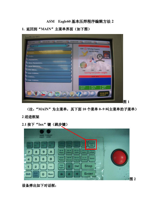
3.2 操作步骤:3.2.1 进⼊菜单Teach→Delete Pragram把原来的程序删除掉;3.2.2 进⼊菜单WH Menu→Setup Lead Frame→输⼊PCB的参数→Serup Magazine→输⼊料盒参数→Fine Adjust此时将拉⼀⽚材料在轨道中,按左右键调整PCB第⼀个单元的位置→按Enter后按A继续调整第⼆单元的位置→同样按Enter后按A继续调整第三、四…单元的位置→调完后按Enter完成拉料位置调整;3.2.3 教读程序:进⼊Teach→Teach Program教读⼀个新程序;3.2.3.1 Teach Indexing PR教读Indexing时的PR以提⾼Index的准确性;3.2.3.2 Teach Aligmment菜单输⼊2并按Enter编写⼿动对点Lead和Die(两个点);3.2.3.3 编写⾃动对点(做PR):Template设定合适的图形⼤⼩和搜索范围→Adjust Image调整灯光直⾄⿊⽩分明(Lead)或看得清析(Die)后按Emter做PR ;3.2.3.4 Auto Wire编写焊线数⽬和位置3.2.4 测量焊针⾼度:进⼊Paramter→Reference parameter测量PCB及晶⽚的⾼度;条线改为N;3.2.6 若有需要进⼊Wire Parameter→Edit BSOB/BBOS Control把N改为B;3.2.7 复制:进⼊Teach→Step Repeat选择合适的模式进⾏复制;如有需要在功能键F15中[10882]Skip Row/Col Map设定跳过没有的⾏或列。
第一页:欲练此功,必先自宫 第二页:即使自宫,未必成功 第三页: 不用自宫,也能成功第 1 页 2013-4-10第一页:欲练此功,必先自宫 第二页:即使自宫,未必成功 第三页: 不用自宫,也能成功第 2 页 2013-4-10第一页:欲练此功,必先自宫 第二页:即使自宫,未必成功 第三页: 不用自宫,也能成功第 3 页 2013-4-10偵測設定tail short路徑: Main \ Auto \ Start single Bond \ 9 Tail shortRange: -15 到15 ,通常設-2 到2設為-15 表偵測功能關閉stickadj路徑:Main \ Auto \ Start Single Bond \ F1 \ 7StickadjRange: sample值為5到30設為35表偵測功能關閉正常設定值須高single Bond時之sample 值如設定值低於Single Bond 之sample值則假偵測關鍵:1須tail break Control off2路徑:Main \ Wire Parameter \ More \ Edit Tail Break Control相對開關:1 stick detect 1路徑:Main \ Auto \ More \ Stick Detect 12 stick detect 2路徑:Main \ Auto \ More \ Stick Detect 23 edit Non-Stick Detection路徑:Main \ Wire Parameter \ Edit Non-Stick Detection第一页:欲练此功,必先自宫第二页:即使自宫,未必成功第三页:不用自宫,也能成功第4 页2013-4-10Tail Stick路徑:Main \ Auto \ Start Single Bond \ F1 \ 9Tail stickRange: sample值為20到170正常設定值須高single Bond時之sample 值如設定值低於Single Bond 之sample值則假偵測關鍵:1須tail break Control YES2路徑:Main \ Wire Parameter \ More \ Edit Tail Break Control1st BND Scrub Settings (摩擦参数意义)第一页:欲练此功,必先自宫第二页:即使自宫,未必成功第三页:不用自宫,也能成功第5 页2013-4-10第一页:欲练此功,必先自宫 第二页:即使自宫,未必成功第三页: 不用自宫,也能成功 第 6 页 2013-4-10第一页:欲练此功,必先自宫 第二页:即使自宫,未必成功第三页: 不用自宫,也能成功 第 7 页 2013-4-10第一页:欲练此功,必先自宫 第二页:即使自宫,未必成功第三页: 不用自宫,也能成功 第 8 页 2013-4-10第一页:欲练此功,必先自宫 第二页:即使自宫,未必成功 第三页: 不用自宫,也能成功 第 9 页 2013-4-10第一页:欲练此功,必先自宫 第二页:即使自宫,未必成功 第三页: 不用自宫,也能成功 第 10 页 2013-4-10第一页:欲练此功,必先自宫第二页:即使自宫,未必成功第三页:不用自宫,也能成功第11 页2013-4-10第一页:欲练此功,必先自宫 第二页:即使自宫,未必成功 第三页: 不用自宫,也能成功 第 12 页 2013-4-10 弧度设置参数和步骤:常用的是Q-LOOP (三角弧度) 和S-LOOP (平弧)第一页:欲练此功,必先自宫 第二页:即使自宫,未必成功 第三页: 不用自宫,也能成功 第 13 页2013-4-10第一页:欲练此功,必先自宫 第二页:即使自宫,未必成功 第三页: 不用自宫,也能成功 第 14 页2013-4-10第一页:欲练此功,必先自宫 第二页:即使自宫,未必成功 第三页: 不用自宫,也能成功 第 15 页2013-4-10。
自动焊线机(EAGLE-60)培训教材培训目的:让设备操作人员掌握正确的设备操作方法,以提升产品质量及生产效率。
培训对象:自动焊线机操作人员。
培训设备型号:EAGLE-60培训内容:一、开机:1、先开气、再开电源(气压4-6Kg/cm2,电压220V);2、打开显示器电源开关3、电源打开后,机台系统进行自检,送料马达搜索原位,大约5分钟后自检完毕,按ENTER键进入待机状态。
二、程序设定:2.1 启动机器,进入主菜单"Teach"项,选择第5项"Delete program",按"Enter"键,提示"Sure to delete program?",按A键,刪除程序,显示"Reset parameter windows?",按"stop"键退出(如按A键,则所有参数将变更)。
2.2 进入主菜单第3项"Teach program",选择第1项"Teach Alignment",按Enter键显示"pairs of align point2",按"Enter"键确认,左屏幕显示"Dieo 1 lead"滚动操作球,将焊头移至左侧第6个支架单元左上角位置,按enter键输入第1个支架对点,将焊头移至右侧第1个支架单元右上角位置,按Enter键确认.2.3 显示"Die 1 Die"移动焊头至第1个Die位置处,使屏幕十字线与晶片电极中心对准,按Enter键2次,输入2个对点;焊头自动跳至第6个支架单元处,要求做支架2nd焊点PR识別,右屏幕显示裝载PR菜单,其中第6项"PR Lead/search mode选择PR识別模式,Binary/Greylvl為黑白与灰度识别常用模式,根据需要进行选择使用.键盘数字键:2=coax , 3=side , 4=Bcoax,分別调节同轴光,侧光及同轴蓝光,1=Threshold调节图象黑白对比度,按一次方向键,增加光亮速度调整;图象调节以清晰为准,按Enter键装载,同理装载晶片PR.2.4 显示"NO.of wire 300"输入"1"条线,按Enter键,选择第4项PRsupport mode将"Both"改为"none",选择0项"Get Bond point",移动操作球,使十字线与晶片电极中心对准,按Enter键一次,输入第1st焊点位置;移动焊动至第2nd焊点焊的位置,按Enter确认之后连续4次退出至主画面,选择第2项step/Repeat,将None改为Ahead 模式,显示 No of repeat rows 1,输入1,显示 No of repeat cols 1,输入7,按Enter键,左屏幕显示"Teach on upper right unit,Enter a lead align pt"将焊头移至最右边第1个支架单元左上角处,按Enter,之后至支架第7单元处,修正支架,使支架与十字线左上角对齐,按Enter键确认结束程序编辑。
TR04700001E For more information visit:January 2007New InformationContentsObjectives . . . . . . . . . . . . . . . . . . . . . 2 Terms to Know . . . . . . . . . . . . . . . . . 2 Product Application . . . . . . . . . . . . . 2 Product Selection . . . . . . . . . . . . . . . 3 Selling Strategies . . . . . . . . . . . . . . .5Pilot devices are a family of related products including pushbuttons, selector switches, indicator lamps, toggle switches and stacklights. In its simplest form, a pilot device is simply a device that provides indication and control of a process to an operator. Value is added when the operator is able to make better decisions regarding the control of the process.Pilot DevicesFor more information visit: TR04700001ETraining MaterialPage 2Effective: January 2007Pilot DevicesObjectives■Recognize Opportunities■ Develop Solution with Related Components■ Compete in the market Terms to KnowThe following terms are used to describe application requirements common to industrial control systems. You should familiarize yourself with the meaning of these terms and the applications they describe.Table 1. Pilot Device GlossaryProduct ApplicationPilot devices are available in many shapes and sizes based on their func-tionality and application. In general, devices are designed for application into two general markets: the IEC(global) market, and the NEMA (North American) market.The NEMA standard does not dictate function and appearance of pilot devices, but the standard does allow the use of industrial market segments to define such requirements. Note: The automotive market segment has adopted a RED “run” indicator standard in which red indicator lights illuminate when machinery is operating and represents a potentially unsafe condition.The IEC standard has adopted strict requirements concerning application of pilot devices. For example IEC 60204-1 requires pushbutton actua-tors be color-coded for universal appli-cation according to the format in Table 2 .Table 2. IEC Color CodingTerm Definitioncontact The conducting part of a switch that operates with another conducting part to make or break a circuitcontact block The part of a pushbutton that is activated when the operator is pressed debouncing The act of removing intermediate noise spikes from a mechanical switch double-break Contacts that break the electrical circuit in two placesdrum switch A manual switch consisting of moving contacts mounted on an insulated rotat-ing shaftlatch An instruction or component that retains its state after a temporary condition occursOFF-delay A timing function that gains value when an input condition transitions from ON to OFFON-delay A timing function that gains value when an input condition transitions from OFFto ONone-shot(interval timer) A timing function that gains value when an input condition transitions from ON to OFF . Output state is maintained while timer is active.pole Number of isolated circuits in a switch devicerelay Device that controls one electrical circuit by manipulating contacts in another circuitthrow Number of closed contact positions per poletransducerDevice that converts physical parameters to electrical signalsColor Meaning ExplanationExamples RedEmergencyActuate in the event of a hazardous condition or emergencyE-Stop, STOP/OFFYellow AbnormalActuate in the event of an abnormal conditionIntervention to suppress abnormal condition. Inter-vention to restart an inter-rupted automatic cycle.Green Normal Actuate to initiate normal conditionSTART/ONBlue MandatoryActuate for a condition requiring mandatory actionReset FunctionWhiteNo specific meaning assignedFor general initiation of func-tions except for emergency stopSTART/ON, STOP/OFF BlackNo specific meaning assignedFor general initiation of func-tions except for emergency stopSTART/ON, STOP/OFFProduct developed for the IEC market is application-rated, requiring lighter duty-ratings than what the NEMA mar-ket requires. For this reason, product is typically 1/3 to 1/2 as expensive and is often positioned as a disposable com-modity in the market. OEM customers appreciate the lower price, which reduces their burden cost that they typically pass on to the end-users.IEC standards 417-IEC-5007 and417-IEC-5008 require START/STOP and ON/OFF controls be marked with uni-versal symbols. Can you determine which symbol represents ON/START and which represents OFF/STOP?Purpose:Purpose:TR04700001E For more information visit: Training MaterialEffective: January 2007Page 3Pilot DevicesProduct SelectionThe 2006 Control Products Catalog, CA08102001E provides product selection tables for pushbuttons, selector switches, indicator lights, potentiometers, enclosures and related accessories in Tab 47. Stacklights and related accessories are supported in Tab 46. The following sections provide an overview of the product groups.E22/EM22 SeriesThis family of pilot device products are developed exclu-sively for the IEC market and include pushbuttons, selector switches, indicator lights, joystick operators, potentiometers and enclosures.Features include:■ 22.5 mm mounting hole■ E22 (plastic) and EM22 (metal) operators share the same contact blocks■EM22 operators provide quick-release mechanism to reduce installation time for OEMs and downtime/replacement costs for end-users■ Tool-less removal of contacts in 3, 5 or 6 block arrangements■NEMA 3/3R/4/4X/12/13 and IEC IP65 ratingsBenefits include:■The E22/EM22 family of products provide some of the shortest panel depth requirements on the market. This benefit translates to greater clearances for panel compo-nents mounted behind the pilot devices.10250T SeriesThis family of pushbutton, selector switch, indicator light and potentiometer devices represents the flagship product for NEMA applications. It is easily recognized by its brilliant chrome finish.Features include:■ 30.5 mm mounting hole■Contact blocks feature “reliability nibs” that ensure long life anddependable switching despite oxida-tion and corrosion on the contact surfaces■ Operators feature “grounding nibs” that ensure electrical grounding of the operator with the panel■ UL 600V AC rating, 10 million operations (mechanical), 1 million (electrical)■NEMA 1/2/3/3R/4/4X/12/13 and IEC IP65 ratingsBenefits include:■New contact block design provides greater visibility with laser-engraved terminal markings and light gray mate-rial. Ultrasonic welding of contact blocks have been eliminated, making the components acceptable for low emissivity ratings required by IEC and other global market standards.E34 SeriesThe E34 family of pilot device products represents the ulti-mate in corrosion-resistant packaging of pilot devices. It uses the same design elements of the 10250T, but replaces the brilliant chrome finish with a triple-layer epoxy finish that is extremely durable.Features include:■Uses the same contact block, operator mounting, and accessories as the 10250T■ Meets NSF requirements for corrosion resistance from continuous salt spray for 200 hours. Tested to 600 hours before visible corrosion appears.Benefits include:■OEMs and panelshops may appreciate the distinctive appearance of their panels provided by the black epoxycoatings of the E34 devices.E22/EM22 FamilyTraining MaterialPage 4Effective: January 2007Pilot DevicesHT800 SeriesThis family of pushbuttons, selector switches, indicator lights and related accessories was developed in response to the need for a family of products that provide basic function-ality at a low price without sacrificing the appearance of a panel that may contain competitive products.Features include:■30.5 mm mounting hole■Transparent contact blocks that mounttwo-across and interlock to preventseparation due to wiring harnessstress■Contact blocks may be mounted inLeft/Right or Top/Bottom positions to accommodate avariety of wiring layouts■Reduced product variation expedites delivery/setup/ inventoryBenefits include:■Lower cost product with basic functionality for customers who don’t need advanced features.E30 SeriesDo you have customers that have outgrown their control panels? This situation is obvious to anyone that walks through a facility and observes pilot devices mounted to the tops, sides and back of existing control panels. If so, theE30 family of products provides an elegant solution by inte-grating the function of pushbutton and indicating light into a single operator.Features include:■30.5 mm mounting hole■Up to six operations in one package■Selector switch and potentiometerdesigns also available■Unique contact block locking mecha-nism provides easy removal of contactswithout disturbing the panel-mounted operators■Customized legends/lensesBenefits include:■This product is well-positioned for applications requiring minimal panel space.E10 Toggle SwitchesOEMs that supply equipment to commercial, retail and light industrial operations may find the E10 family of selector switches and plunger toggle switches to be an ideal solution for light-duty switching of resistive and inductive loads. Features include:■0.468" mounting hole■Packaged in quantities of 10■1 – 4 poles, single and doublethrowBenefits include:■These operators make idealcompanions to much largerindustrial switches when sec-ondary control is required for remote operation.E29 Indicator LightsFor those applications requiring only status indication, the E29 indicators provide exceptional reliability.Features include:■17 mm hole providescompact panel mount-ing■Heavy-duty, oil-tightdesign features polycarbonate or glass lenses■Transformer or full-voltage capabilityBenefits include:■The PresTest capability ensures reliable operation. Simply press the lens to test the bulb. Designate a single pushbut-ton as a Master Test device to illuminate the entire panel of indicators at once.E26 StacklightsConcerned with visibility of indicator lights, or per-haps you’d like to add audible alarms to a controlpanel? If so, the E26 series of stacklight productsprovide the solution in the most demanding environments.Features include:■Modular design allows customized appearance of colors and blink rates (clear, red, yellow,green, blue, amber)■Supports monotone, bitone, and intermittent audible alarming■Incandescent, LED or xenon strobe lampsBenefits include:■The lamps are designed to interact with a wide range of control signals, from 12 to 240V.Mounting is accommodated through a varietyof bases, including 3/4" NPT, 3- or 4-holedesigns.For more information visit: TR04700001ETraining MaterialEffective: January 2007Page 5 Pilot DevicesSelection SummaryThe following table provides general guidelines for applica-tion of the various pushbutton, selector switch and indicator light products.Table 3. Product ApplicationsᕃThe E34 family of devices is sensitive to UV light when applied in out-door applications. The devices will appear slightly discolored after long periods of exposure to direct sunlight. The functionality of the device is not affected.Selling StrategiesEaton has a comprehensive selection of IEC and NEMA pilot devices as open components or assembled in packages for enclosed and MCC.Selection — Eaton provides complementary product lines in addition to the basic pilot devices. These products include metallic and nonmetallic enclosures, signal conditioning and isolation transformers, sensors and programmable controls.Customization — Warehouses in Spartanburg, SC, and Memphis, TN, support customized labelling of legend plates and lenses for all pilot devices. Order forms are included in the catalog.Ease of Installation — No tools are required for the IEC rated devices and modular assemblies support the installation of operators separate from the contact blocks for the NEMA rated devices. Products may be ordered fully assembled or as separate components.How do Eaton’s Cutler-Hammer products compete? Reinforce the capability of the 48 hour mod center, our warehouse stocking, ProShop training, regional service centers and faster delivery.Table 4. ServiceIndoor Outdoor Washdown Corrosive Explosive10250T Yes Yes Yes No YesHT800Yes No Yes No NoE34Yes Yes ᕃYes Yes YesE30Yes No No No NoEM22Yes Yes No No NoE22Yes Yes No No NoResources Value AddManufacturing Facilities (Chicago, Denver, Los Angeles, Hartford, Houston)Regional support for entire product line. Open to customer visits. Able to ship quickly.Warehouses Provide balance for distributorstockingProShops Distributor support provides own-ership of solutionMod Center Flexibility of solutionsTR04700001E For more information visit: Eaton Electrical Inc.1000 Cherrington ParkwayMoon Township, PA 15108-4312USAtel: 1-800-525-2000© 2007 Eaton CorporationAll Rights ReservedPrinted in USAPublication No. TR04700001E/CPGJanuary 2007。
Eagle60自动焊线机培训大纲一.机台外部基本构造介绍;二.开机步骤;三.关机步骤;四.正常换型号调机步骤;五.常见品质异常问题及原因分析;六.常见错误讯息介绍;七.注意事项.一.机台外部构成介绍○1三色显示灯;○2两台显示器;○3键盘;○4左右升降台;○5轨道组件;○6焊头组件等.二.开机步骤1.打开气压源;2.按下绿色电源开关,等待机台进入主菜单.三.关机步骤1.关闭气压源;2.进入主菜单下8Utilities 2.seandby mode;3.等待出现Press Any key 时,关闭红色电源开关.四.正常换型号调机步骤1.轨道高度调整进入MAIN 6.WH MENU 9.Prack,利用上下箭头设定支架高度,以压板刚好压在杯沿下为准,Ener stop;2.支架位移调整按INX键送一片支架到压板中,在MAIN 6.WH MENU 3.Fine Adjust A;按左右键调节支架位置,要求压板能够刚好将1、2焊点压紧,调节完第一单元后按Enter按A继续调节第二个单元;3.编写程序3-1.删除程序:在MAIN 1.TEACH5.Delete Program A stop;3-2.建立新程序:在MAIN ITEACH3.Teach Program;3-2-1.对点设立MAIN TEACH Tech program Teach Alignment 单晶设2个参考点,双晶设3个 3 change lens 对第6颗支架第二焊点心Enter 对第一颗晶粒的第二个电极Enter,对完参考点后,会自动进入黑白对比度画面;3-2-2.做黑白对比度(做IST PR)对第六颗支架的二焊点1.Adjust Imagc 按上下键头调节亮度Enter 自动跳至第一颗支架的二焊点按上/下键调节亮度Enter 7.PR Load/Search Mode (把Graylul改为Binary)对晶片的第一电极1.Adjust Imagc按上下键调节亮度Stop 7 PR Load/Search Mode ( 把Binary改为Graylul)1Adjust Imagc 对晶片的第一个电极Enter 对晶片的第二个电极Enter;3-2-3.编写线自动进入编写线菜单,将4PR Support Mode(把Both改为None),把十字线对准第一个晶片的第一个电极0.Get Bond Point 将十字线对第一条线的第二焊点Enter 把十字线对到第一个晶片的第二个电极上Enter 将十字线对到第二条线的二焊点 2.Chage Bond On Enter 1 AEnter stop.4.复制MAIN TEACH 2.Step&Repeat(把None改为Ahead)No of Repeat Rowsl Enter No of Repeat Cols 1,把1改为7对第一颗支架二焊点Enter 对第二颗支二焊点Enter stop;5.设定跳过的点F1 15 Enter 200 2 8 misc control 2 skip Row/Col/Map NO,NO,NO改为NO,NO,C1;6.关闭第一条线一焊点检测功能MAIN 4.Wire Parameters A.Edit Non-stick Detection 0.Edit stick Detection 1 按F1选ODD,把Y改为Nstop;7.做做瓷咀探测高度MAIN 3.Parameters 2.Refereme Parameters Enter,对支架二焊点中心Enter 按下键头选一个晶片Enter对晶片电极Enter,把NO改为YES F1 Enter,对大杯第二焊点Enter stop;8.线弧和焊接参数设定完成前面7项后,先焊接一两个点进行观察,根据实际情况调整线弧及焊接相关参数:○1MAIN-4-3项,设定线弧模式,一般用Q;○2MAIN-3-1项,设定基本焊接参数;五.常见品质异常问题的基本原因分析1.松焊、空焊:查看时间Time、功率Power、压力Force是否设定正确,预备功率是否过低,搜索压力是否过小或两个焊点是否压紧等;A.TIME(时间):一般在10-20MS之间;B.POWER(功率):第一焊点一般35-80之间;第二焊点一般45-180之间;C.FORCE(压力):第一焊点一般30-50之间;第二焊点一般50-180之间.2.焊球变形:第二焊点是否焊上或焊接功率是否设得过大,烧球时间或线尾是否设得过长,支架是否压紧或瓷咀是否过旧;3.错焊、位置不当:焊接程序和PR是否有做好,焊点同步是否设定正确,搜寻(search)范围是否设得太大等;4.球劲撕裂:检查功率压力是否设得过大,支架是否压紧,或者适当减小接触功率,瓷咀是否破裂或用得太久;5.拉力不足:焊点功率、压力是否设得太大,支架有否压紧,瓷咀是否已超量使用而过旧(好瓷咀一般使用500K/支).六.常见错误讯息的认识B13表示无烧球或断线;B3/B5 表示PR识别错误,支架PR 被拒收;B4/B6 表示PR识别错误,晶片PR被拒收;B8表示第一焊点不粘或未焊上;B9表示第二焊点不粘或未焊上;W1 表示搜寻传感器错误或支架位置错误.七.注意事项1.温度设定:240℃-300℃之间(蓝/白光设定为230℃左右);2.在AUTO BOND MENU下必须开启之功能:(1) ENABLE PR YES(2)AUTO INDEX YES(3)BALL DETECT YES(4)STICK DETECT1 YES(5)STIEK DETECT2 YES3.保持轨道清洁,确保送料顺畅;4.安全问题:穿线时手勿接触焊头部位,以防高温烧手;5.机台日常保养必须确实认真执行;6.金线轮检测器定期清洁;7.余金线请收好,切勿乱扔;8.除本操作介绍的功能项目和参数外,其它功能项目和参数。
Eagle60自动焊线机培训大纲一.机台外部基本构造介绍;二.开机步骤;三.关机步骤;四.正常换型号调机步骤;五.常见品质异常问题及原因分析;六.常见错误讯息介绍;七.注意事项.一.机台外部构成介绍○1三色显示灯;○2两台显示器;○3键盘;○4左右升降台;○5轨道组件;○6焊头组件等.二.开机步骤1.打开气压源;2.按下绿色电源开关,等待机台进入主菜单.三.关机步骤1.关闭气压源;2.进入主菜单下8Utilities 2.seandby mode;3.等待出现Press Any key 时,关闭红色电源开关.四.正常换型号调机步骤1.轨道高度调整进入MAIN 6.WH MENU 9.Prack,利用上下箭头设定支架高度,以压板刚好压在杯沿下为准,Ener stop;2.支架位移调整按INX键送一片支架到压板中,在MAIN 6.WH MENU 3.Fine Adjust A;按左右键调节支架位置,要求压板能够刚好将1、2焊点压紧,调节完第一单元后按Enter按A继续调节第二个单元;3.编写程序3-1.删除程序:在MAIN 1.TEACH5.Delete Program A stop;3-2.建立新程序:在MAIN ITEACH3.Teach Program;3-2-1.对点设立MAIN TEACH Tech program Teach Alignment 单晶设2个参考点,双晶设3个 3 change lens 对第6颗支架第二焊点心Enter 对第一颗晶粒的第二个电极Enter,对完参考点后,会自动进入黑白对比度画面;3-2-2.做黑白对比度(做IST PR)对第六颗支架的二焊点Adjust Imagc 按上下键头调节亮度Enter 自动跳至第一颗支架的二焊点按上/下键调节亮度Enter 7.PR Load/Search Mode (把Graylul改为Binary)对晶片的第一电极1.Adjust Imagc按上下键调节亮度Stop 7 PR Load/Search Mode ( 把Binary改为Graylul)1Adjust Imagc 对晶片的第一个电极Enter 对晶片的第二个电极Enter;3-2-3.编写线自动进入编写线菜单,将4PR Support Mode(把Both改为None),把十字线对准第一个晶片的第一个电极0.Get Bond Point 将十字线对第一条线的第二焊点Enter 把十字线对到第一个晶片的第二个电极上Enter 将十字线对到第二条线的二焊点 2.Chage Bond On Enter 1 AEnter stop.4.复制MAIN TEACH 2.Step&Repeat(把None改为Ahead)No of Repeat Rowsl Enter1,把1改为7对第一颗支架二焊点Enter 对第二颗支二焊点Enter stop;5.设定跳过的点F1 15 Enter 200 2 8 misc control 2 skip Row/Col/Map NO,NO,NO改为NO,NO,C1;6.关闭第一条线一焊点检测功能MAIN 4.Wire Parameters A.Edit Non-stick Detection 0.Edit stick Detection 1 按F1选ODD,把Y改为Nstop;7.做做瓷咀探测高度MAIN 3.Parameters 2.Refereme Parameters Enter,对支架二焊点中心Enter 按下键头选一个晶片Enter对晶片电极Enter,把NO改为YES F1 Enter,对大杯第二焊点Enter stop;8.线弧和焊接参数设定完成前面7项后,先焊接一两个点进行观察,根据实际情况调整线弧及焊接相关参数:○1MAIN-4-3项,设定线弧模式,一般用Q;○2MAIN-3-1项,设定基本焊接参数;五.常见品质异常问题的基本原因分析1.松焊、空焊:查看时间Time、功率Power、压力Force是否设定正确,预备功率是否过低,搜索压力是否过小或两个焊点是否压紧等;A.TIME(时间):一般在10-20MS之间;B.POWER(功率):第一焊点一般35-80之间;第二焊点一般45-180之间;C.FORCE(压力):第一焊点一般30-50之间;第二焊点一般50-180之间.2.焊球变形:第二焊点是否焊上或焊接功率是否设得过大,烧球时间或线尾是否设得过长,支架是否压紧或瓷咀是否过旧;3.错焊、位置不当:焊接程序和PR是否有做好,焊点同步是否设定正确,搜寻(search)范围是否设得太大等;4.球劲撕裂:检查功率压力是否设得过大,支架是否压紧,或者适当减小接触功率,瓷咀是否破裂或用得太久;5.拉力不足:焊点功率、压力是否设得太大,支架有否压紧,瓷咀是否已超量使用而过旧(好瓷咀一般使用500K/支).六.常见错误讯息的认识B13表示无烧球或断线;B3/B5 表示PR识别错误,支架PR 被拒收;B4/B6 表示PR识别错误,晶片PR被拒收;B8表示第一焊点不粘或未焊上;B9表示第二焊点不粘或未焊上;W1 表示搜寻传感器错误或支架位置错误.七.注意事项1.温度设定:240℃-300℃之间(蓝/白光设定为230℃左右);2.在AUTO BOND MENU下必须开启之功能:(1) ENABLE PR YES(2)AUTO INDEX YES(3)BALL DETECT YES(4)STICK DETECT1 YES(5)STIEK DETECT2 YES3.保持轨道清洁,确保送料顺畅;4.安全问题:穿线时手勿接触焊头部位,以防高温烧手;5.机台日常保养必须确实认真执行;6.金线轮检测器定期清洁;7.余金线请收好,切勿乱扔;8.除本操作介绍的功能项目和参数外,其它功能项目和参数。
Eagle60-03培训资料
一、键盘各键含义
Corbnd: 手动焊线Panlgt: 打开/关闭照明灯光
CLPsol: 打开/关闭压板Ctctsr: 探测磁嘴高度
Zoom: 镜头放大倍率转换Wclmp: 打开/关闭线夹
Prew: 上一页Next: 下一页
EFO: 手动打火烧球INX: 单元位移
IM↑: 进料盒前进一格 IM↓: 进料盒后退一格
IM HM: 更换进料盒 O/Ctk: 打开/关闭轨道
Nwepgm: 编写新程序 Main: 返回主菜单
Edwire: 编写焊线位置 EdPR: 编写PR图像
Wire Feed: 线圈马达单步动作 Ldpgm: 载入焊线程序
OM↑: 出料盒前进一格 OM↓: 出料盒后退一格
OM HM: 更换出料盒 Clr tk: 清除轨道
PgUp: 向下翻页 Edloop: 编辑线弧参数
ChgCap: 更换磁嘴 Dmbnd: 切断线尾
BOND: 进入自动焊线菜单 THREAD WIRE: 单步吹气
二、焊线程序编写
1.进入MAIN主菜单选择(1)Teach并进入
2.选择(5)DELETE PROGPRAM进入删除原程序,STOP退出
3.选择(3)TEACH PROGRAM,开始编写程序
4.选择(1)TEACH ALIGNMENT 进入,出现对话框更改参考点的数目
5.选择(0)Get alignment point并进入,左边屏幕显示Die0 pt1
6.将光标移至第三颗材料负极的一角按ENTER,左边屏幕提示Die0 pt2,然后将
光标移至第一颗材料负极的相同位置并按ENTER
7.左边屏幕提示Die1 pt1,此时将光标移至第一条线第一焊点参考点位置并按ENTER,左边屏幕提示Die1 pt2,此时将光标移至第二条线第一焊点参考点位置并按ENTER
8.左边屏幕提示Die2 pt1,此时交光标移至第一条线第二焊点第一参考点位置并按ENTER,左边屏幕提示Die2 pt2,此时将光标移至第一条线第二焊点第二参考点位置并按ENTER(两参考点不可选同一点)
9.左边屏幕提示Die1 pt1,此时交光标移至第二条线第二焊点第一参考点位置并按ENTER,左边屏幕提示Die1pt2,此时将光标移至第二条线第二焊点第二参考点位置并按ENTER
10.此时焊头自动回每三颗材料位置,左边屏幕提示Die0 pt1,此时开始调节参考点的PR
11.选择(3)TEMPLAT并进入将0设为11,然后利用上下、左右键设定识别框的大小,OK后按ENTER确认
12.选择(1)Adjust Image并进入利用上下键调节灯光亮度,OK后按ENTER焊自动回运至第一颗材料相同位置,直接按ENTER,焊头回至晶片位置
13.用11、12相同的方法调整第一条线第一焊点的识别,后做第二颗,按ENTER 确认
14.左边屏幕提示Die3 pt1,此时将光标移至第二条线第二焊点第一参考点位置调整识别框大小、灯光亮度后按ENTER确认,左边屏幕提示Die3 pt2,此时将光标移至第二条线第二焊点第二参考点位置并按ENTER确认,参考点识别图像完成
15.右边屏幕出现对话框NO of wire 300,将300改为2,按ENTER确认,16.选(4)PR support mode,将Both改为None
17.将光标移至第一条线第一焊点中心,选择(0)Get bond point按ENTER,将光标移至第一条线的第二焊点,选择(2)Change Bond on进入选B显示对话框Input die number 1,将1改为2,然后出现另一个对话框选A,按ENTER 确认
18.将光标移至第二条线第一焊点中心按ENTER,将光标移至第二条线第二焊点,然后选择(2)Change Bond on进入,选B显示对话框Input die number 1,将1改为3,然后出现另一个对话框选A,按ENTER确认
19.按STOP退至TEACH主菜单,选(2)Step& repeat None将None改为Hybrev 按ENTER出现对话框NO of repeat row 1,按ENTER出现另一个对话框NO of repeat colg 1将1改为7按ENTER
20.将光标移至第一颗材料碗杯上一点按ENTER,然后将光标移到第二颗材料相同点按ENTER,焊头自动们移至第7颗,将光标对准前两次相同的点按ENTER,按STOP退至MAIN主菜单
21.选(3)Parameter进入,选(2)Reference parameter进行瓷嘴高量测22.调整焊接参数、确认温度无误后,穿线、烧球后即可开始自动焊线。