SEW编码器介绍PPT
- 格式:ppt
- 大小:3.35 MB
- 文档页数:24
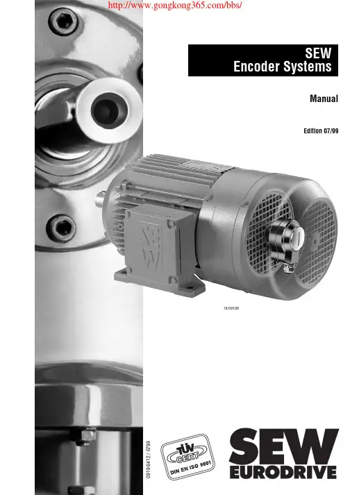
18/005/98SEW Encoder SystemsManualEdition 07/990919 6412 / 07992SEW encoder systems01861AEN Fig. 1: Unit designation of SEW encoder systems E S 1 T E Incremental encoder (encoder)A Absolute encoder N Proximity sensor X Non-SEW encoder S Spread shaft V Solid shaft H Hollow shaft E n c o d e r t y p e S h a f t d e s i g n S p e c i f i c a t i o n I n t e r f a c e t o e v a l u a t i o n A Design as mounting device C V = 24 V , HTL with zero track and negated signals R V = 24 V , TTL RS-422S V = 24 V , sin/cos 1 V T V = 5 V , TTL RS-422Y SSI interface 6 Number of pulses per revolution (proximity sensor)DC DC DC SS DC 12DesignPage 1System Description (4)1.1System overview (4)2Technical Data (7)2.1Technical description (7)2.1.1Incremental encoders with TTL and HTL signals (7)2.1.2Incremental encoders with high-resolution sin/cos signals (9)2.1.3Absolute encoders with MSSI interface (10)2.1.4Resolver (12)2.1.5Proximity sensors (13)2.2Incremental encoders (14)2.2.1Incremental encoders with spread shaft (14)2.2.2Incremental encoders with solid shaft (15)2.3Absolute encoder (16)2.4Resolver (17)2.5Proximity sensors (18)2.6Mounting devices (19)3Installation (20)3.1General information (20)3.2Incremental encoders (21)3.2.1Encoders for MOVITRAC® 31C frequency inverters (21)3.2.2Encoders for MOVIDRIVE® MDV60A drive inverters (22)3.3AV1Y absolute encoder (24)3.3.1Absolute encoder with MOVIDYN® MAS/MKS51A servo controller (24)3.3.2Connection of absolute encoder to MOVIDRIVE® MDS60A drive inverter (25)3.3.3Absolute encoder with MOVIDRIVE® MDV60A drive inverter (25)3.4Resolver (26)3.4.1Resolver with MOVIDYN® MAS/MKS51A servo controller (26)3.4.2Resolver with MOVIDRIVE® MDS60A drive inverter (27)3.5Proximity sensors (28)3.6Extended motor versions with encoder and mounting devices (29)3.6.1Incremental encoders ES1_/ES2_/EV1_ (29)3.6.2Encoder mounting devices ES1A/ES2A/EV1A (31)3.6.3Absolute encoder AV1Y (34)3.6.4Encoder mounting devices AV1A (36)3.7Pre-fabricated cables (37)SEW encoder systems34SEW encoder systems 11System Description 1.1System overview 01863BEN Fig. 2: System overview, SEW drive electronics and encoder systems Electronically controlled drive systems require actual value sensing and speed feedback; drives with synchronous motors also require the angle of the rotor position. As a systems supplier, SEW offers a comprehensive range of encoder systems.Various mounting devices are available to connect non-SEW encoders to SEW motors.Proximity sensors represent an inexpensive and easy-to-fit solution, if all that is required is theinformation about whether or not the drive is turning and in which direction.Encoders Absolute encoders and resolvers Encoder systems for asynchronous AC motors Encoder systems for synchronous motors1SEW encoder systems for asynchronous AC motors:•Incremental encoders-for5V DC supply voltage and with 5 V TTL signal level according to RS-422recommended for operation with the MOVITRAC® 31C frequency inverter-for24V DC supply voltage and with high-resolution sinusoidal signal levelrecommended for operation with the MOVIDRIVE® drive inverter-for24V DC supply voltage and with 5 V TTL signal level according to RS-422-for24V DC supply voltage and with 24V HTL signal level•Absolute encoder-for15V DC supply voltage and with MSSI interface-for24V DC supply voltage and with MSSI interface and two sinusoidal tracks•Proximity sensors-with six pulses per revolution-with A track or A+B track•Mounting devices for non-SEW encoders-mounting of spread shaft-mounting of full shaft with couplingSEW encoder systems for asynchronous servomotors:•Incremental encoders-for24V DC supply voltage and with high-resolution sinusoidal signal levelstandard feature in CT/CV motors-for24V DC supply voltage and with 5 V TTL signal level according to RS-422•Absolute encoder-for24V DC supply voltage and with MSSI interface and two sinusoidal tracksSEW encoder systems for synchronous servomotors:•Resolverstandard with synchronous servomotors for speed control•Absolute encoder15/24 V DC supply voltage with MSSI interfaceEncoder selection based on setting range:•Setting range up to 1:3000-with asynchronous AC motors → encoder with TTL signals and1024 increments/revolution-with synchronous motors → built-in resolver•Setting range up to 1:5000-with asynchronous AC motors → encoder with high-resolution sinusoidal signal levels-with asynchronous servomotors → encoder with high-resolution sinusoidal signal levelsSEW encoder systems56SEW encoder systems 1All encoder systems at a glance: *recommended encoder for operation with MOVITRAC ® 31C **recommended encoder for operation with MOVIDRIVE ® Mounting devices for non-SEW encoders Name For SEW motor size Type of encoder Shaft Specification Supply Signal ES1T*CT/DT 71...100Encoder Spread shaft - 5 V DC controlled 5 V DC TTL RS-422ES1S**24 V DC 1 V SS sin/cos ES1C 24 V DC HTL ES1R 5 V DC TTL RS-422ES2T*CV/DV 112...132S 5 V DC controlled 5 V DC TTL RS-422ES2S**24 V DC 1 V SS sin/cos ES2C 24 V DC HTL ES2R 5 V DC TTL RS-422EV1T*CT/CV71...180DT/DV71...225Solid shaft 5 V DC controlled 5 V DC TTL RS-422EV1S**24 V DC 1 V SS sin/cos EV1C 24 V DC HTL EV1R 5 V DC TTL RS-422NV16DT/DV 71...132S Proximity sensor Solid shaft A track 24 V DC 6 pulses/revolu-tion, NO contact NV26A+B track AV1Y DS56DY71...112CT/CV71...180DT/DV71...225Absolute encoder Solid shaft -15/24 V DC MSSI interface and 1 V SS sin/cos Name For SEW motor size Type of encoder Shaft Specification Supply Signal ES1A DT71...100Non-SEW encoder Spread shaft -Configured as mounting device ES2A DV112...132S EV1A DT/DV71...225Solid shaft AV1A DS56, DY71...112Solid shaft XV1A DT/DV71...225Solid shaftSEW encoder systems722Technical Data2.1Technical descriptionThis chapter explains the various types of signals, signal tracks and signal levels. The signal tracks are represented in the form of timing diagrams.Encoders have a sturdy light metal housing and generously sized precision ball bearings. Their solid metal housing protects the encoders against interference, which lends them a high degree of electromagnetic compatibility.2.1.1Incremental encoders with TTL and HTL signalsEncoders convert the angle of rotation input parameter into a number of electrical pulses. This is performed by means of an incremental disc incorporating radial slits permitting the passage of light. These slits are scanned by opto-electronic means. The number of slits defines the resolution (pulses/revolution).Signal tracks:SEW encoders are encoders with two tracks and one zero pulse track, which results in six tracks due to negation. Two light barriers are arranged at right angles to one another in the encoder. They supply two pulse sequences on tracks A (K1) and B (K2). Track A (K1) is 90° ahead of B (K2) when the encoder is turning clockwise (to the right as viewed looking onto the motor shaft, the “A” side).This phase relationship is used for determining the direction of rotation of the motor. The zero pulse (one pulse per revolution) is sensed by a third light barrier and made available on track C (K0) as a reference signal. With TTL encoders, tracks A (K1), B (K2) and C (K0) are negated in the encoder and made available on tracks A (K1), B (K2) and C (K0) as negated signals.01877AXXFig. 3: TTL signals with zero track and negated signalsHTL signals with zero track, but without negated signals 90°90°180°360°A (K1)A K1()B (K2)B K2()C (K0)C K0()8SEW encoder systems 2Signal levels:•TTL (T ransistor T ransistor L ogic) version The signal levels are V low ≤ 0.5 V and V high ≥ 2.5 V. The TTL signals are transmitted symmetri-cally and evaluated differentially. This design makes them resistant to asymmetrical interference and ensures good EMC behavior. The signal is transmitted in accordance with the RS-422 inter-face standard.Units with a 5 V DC encoder supply voltage, e.g. MOVITRAC ® 31C, allow the user to measure the actual supply voltage at the encoder via sensor leads. The supply voltage is corrected to 5 V DC and compensates for the voltage drop along the supply cable to the encoder. Encoders with 24 V DC supply voltage do not require any supply voltage compensation and, thus, no sensor leads.The maximum permissible distance between encoder and inverter is limited by the maximum pulse frequency of the encoder signals. SEW permits a maximum distance between encoder and inverter of 330 ft. (100 m).02542AEN Fig. 4: View of TTL signal levels •HTL (H igh-voltage T ransistor L ogic) version The signal levels are V low ≤ 3 V and V high ≥ V B minus 3.5 V. The HTL encoder is evaluated without the negated tracks; the signals cannot be evaluated differentially. The HTL signals are, therefore, suscep-tible to asymmetric interferences affecting the EMC behavior.V B is the encoder supply voltage in the range of 10 to 30 V DC , with 24 V DC +/- 20% being the most common value. HTL encoders do not require any supply voltage compensation and, thus, no sensor leads. The large voltage range between V high -V Low results in a high current consumption. A fact that has to be taken into consideration when planning the encoder supply.The maximum permissible distance between encoder and inverter is limited by the maximum pulse frequency of the encoder signals. SEW permits a maximum distance between encoder and inverter of 330 ft. (100 m).02543AEN Fig. 5: View of HTL signal levels 552.52.50.50.500TTL K K V [V ]DC "1" range "1" range "0" range "0" range V [V ]DC 2420.503HTL K V [V ]DC "1" range "0" rangeSEW encoder systems922.1.2Incremental encoders with high-resolution sin/cos signalsEncoders with high-resolution sin/cos signals are referred to as sine encoders. They provide two sine signals offset by 90°. The zero passages and the amplitudes (arc tan) of the sine/cosine waves are evaluated. This means the speed can be determined with a very high resolution. This encoder is suitable for drives which are operated with a wide setting range in conjunction with the require-ment to move smoothly at low speed.Signal tracks:SEW sinusoidal encoders are also dual-track encoders with a zero pulse and negated signals,resulting in six tracks. The 90° offset sine signals are on track A (K1) and B (K2). One sine half-wave per revolution is provided at track C (K0) as the zero pulse. Tracks A (K1), B (K2) and C (K0)are negated in the encoder and made available on tracks A (K1), B (K2) and C (K0) as negated sig-nals.01917AXXFig. 6: sin/cos signal s with zero track and negated tracksSignal levels:•The sine/cosine signals are superimposed on a DC voltage of 2.5 V. They have a peak-to-peak voltage of V SS = 1 V. This arrangement avoids voltage zero during signal transmission. The sine/cosine signals are transmitted symmetrically and evaluated differentially. This design makes them resistant to asymmetrical interference and ensures good EMC behavior. The signal is transmitted in accordance with the RS-422 interface standard. The supply voltage is 24 V DC .Sine encoders do not require any supply voltage compensation and, thus, no sensor leads.The maximum permissible distance between encoder and inverter is limited by the maximum pulse frequency of the encoder signals. SEW permits a maximum distance between encoder and inverter of 330 ft. (100 m).90°90°180°360°A (K1)A K1()B (K2)B K2()C (K0C C0()1V10SEW encoder systems 22.1.3Absolute encoders with MSSI interface SEW absolute encoders have a code disc with Gray Code instead of the incremental disc. This code disc is scanned by opto-electronic means. Every angle position has a unique code pattern assigned to it. The absolute position of the motor shaft is determined using this code pattern. The special feature of Gray Code is that only one bit changes with the transition from one resolvable angle stepto the next. This means the possible reading error is max. 1 bit.01927AXX Fig. 7: Code disc with Gray Code Multi-turn:In addition to the code disc for sensing the angle position, multi-turn absolute encoders have addi-tional code discs for absolute sensing of the number of revolutions. These code discs are only sep-arated from each other by one gear unit stage with the reduction i = 16. With three additonal code discs (number usually installed), 16 x 16 x 16 = 4096 revolutions can be resolved absolutely.02383AEN Fig. 8: Arrangement of code discs A single-turn absolute encoder with 12 bit resolution requires 12 pulses to display the 4096 mea-suring steps per revolution. A multi-turn absolute encoder with three additional code discs requires 12 additional pulses to display the 4096 distinguishable revolutions.Single-turn evaluation Pulse 123456789101112Data 20 21 22 23 24 25 26 27 28 29 210 211 Measuring steps per revolution in addition with multi-turn evaluation Pulse 131415161718192021222324Data 20 21 22 23 24 25 26 27 28 29 210 211 distinguishable revolutions i = 16i = 16i = 16Code discs for sensing the number of revolutions Code disc for sensing of angle position Decimal Gray Code Decimal Gray Code 00000811001000191101200111011113001011111040110121010501111310116010114100170100151000Signal outputs:Every scanned code pattern is a parallel data package and is read by a parallel/serial converter. The inverter must request the position value with a defined pulse sequence in order to transmit a posi-tion value from the encoder to the inverter. The pulse sequence starts by converting the current parallel data package and transmitting it to the inverter. The input of the parallel/serial converter is inhibited by the monoflop for the duration of the pulse sequence.01923AENFig. 9: Signal conditioning in absolute encoders with SSI interfaceIn addition to the absolute angle position, the SEW absolute encoders generate the incremental encoder signals A (K1), A (K1), B (K2)und B (K2) and make them available as 1 V SS sine signals.Signal transmission:SEW absolute encoders have an SSI interface (SSI = S ynchronous S erial I nterface) to transmit the absolute value signals and a RS-485 interface for transmission of the 1 V SS sine signals.01928AENFig. 10: Pulse diagram of data transmission via SSI interfaceInverterCycleSerialdataParallel dataCode discDriver InputcircuitSchmitt trigger P a r a l le l /S e r ialconverterPhoto transmitter Photo receiver MonoflopShift SI SOCycleSerialdataMonoflop P/SParalleldata2.1.4ResolverThe resolver determines the absolute position of the motor shaft. It consists of a rotor coil and two stator windings offset by 90° in relation to each other. It operates according to the principle of the rotary transformer. Furthermore, the resolver has one auxiliary winding each in the stator and on the rotor in order to transfer the supply voltage to the rotor without brushes. Both rotor windings are electrically connected.01931AEN Fig. 11: Schematic diagram and equivalent circuit diagram of the resolverSignal outputs:Voltages of varying magnitudes are induced in the stator windings depending on the rotor position. Voltages V1 and V2 on the two stator windings are modulated by the supply voltage through induc-tion. They possess sinusoidal envelopes. The two envelopes are electrically offset by 90° from one another and are evaluated in the inverter for zero passage and amplitude. This enables the rotor position, speed and direction of rotation to be established.00058AXX Fig. 12: Output voltages V1 and V2 of the resolverSignal level:The amplitude of the envelope depends on the r.m.s. value and frequency of the supply voltage V e.γS1S3S4S2R1R2V1stator statorrotorV2V RV estatorstationaryrotating stationarystationaryV2VRV1V1V22.1.5Proximity sensorsProximity sensors represent a simple and inexpensive means of monitoring whether the motor is turning. By using a two-track proximity sensor, it is also possible to determine the direction in which the motor is rotating. Proximity sensors are mounted on the side of the fan guard, and thus do not add to the length of the motor.Signal outputs:Proximity sensors react to the attenuation lugs on the fan. The number of attenuation lugs deter-mines the number of pulses per revolution.01929AXXFig. 13: Setup of the proximity sensor systemThe proximity sensors are constructed with HTL technology and have an NO contact output which is actuated every time there is a pulse. This NO contact output switches the connected supply volt-age. Proximity sensors have a mark-to-space ratio of 1:1.01930AENFig. 14: Signal output of the proximity sensorsSignal level:The signal level is determined by the supply voltage, usually 24 V DC. 90°ABPNPPNPV BV Badditional with two-track proximity sensor2.2Incremental encoders 2.2.1Incremental encoders with spread shaft 01934AXX Fig. 15: SEW encoder with spread shaft *recommended encoder for operation with MOVITRAC ® 31C**recommended encoder for operation with MOVIDRIVE ® Encoder type for asynchronous AC motors 71...100ES1T*ES1S**ES1R ES1C Encoder type for asynchronous AC motors 112...132S ES2T*ES2S**ES2R ES2C Supply voltage V B 5 V DC ±5 %24 V DC ±20 %Max. current consumption I in 180 mA RMS 160 mA RMS 180 mA RMS 340 mA RMS Max. pulse frequency f max 120 kHz Pulses (sine periods) per A, B revolution C 10241Output amplitude per track V high V low ≥ 2.5 V DC ≤ 0.5 V DC 1 V SS ≥ 2.5 V DC ≤ 0.5 V DC ≥ V B minus 3.5 V DC ≤ 1.5 V DC Signal output 5 V TTL sin/cos 5 V TTL HTL Output current per track I out 20 mA RMS 40 mA RMS 20 mA RMS 60 mA RMS Mark-to-space ratio 1 : 1 ±20 %Phase angle A : B 90° ±20 %Ambient temperature ϑamb -25 °C...+60 °C (EN 60721-3-3, class 3K3)Enclosure IP56 (EN 60529)Connection Terminal box on encoder2.2.2Incremental encoders with solid shaft01935AXXFig. 16: SEW encoder with solid shaft*recommended encoder for operation with MOVITRAC ® 31C **recommended encoder for operation with MOVIDRIVE ®Encoder type EV1T*EV1S**EV1R EV1C For motors asynchronous AC motors DT/DV/D 71 (225)Supply voltage V B 5 V DC ±5 %24 V DC ±20 %Max. current consumption I in 180 mA RMS 160 mA RMS 180 mA RMS 340 mA RMS Max. pulse frequency f max 120 kHzPulses (sine periods) per A, B revolution C 10241Output amplitude per track V highV low ≥ 2.5 V DC≤ 0.5 V DC 1 V SS ≥ 2.5 V DC ≤ 0.5 V DC ≥ VB minus 3.5 VDC≤ 1.5 V DCSignal output 5 V TTL sin/cos 5 V TTL HTL Output current per track I out 20 mA RMS 40 mA RMS 20 mA RMS 60 mA RMS Mark-to-space ratio 1 : 1 ±20 %Phase angle A : B 90° ±20 %Ambient temperature ϑamb -25 °C...+60 °C (EN 60721-3-3, class 3K3)Enclosure IP56 (EN 60529)Connection Terminal box on encoder2.3Absolute encoder01933BXX Fig. 17: SEW absolute encoderEncoder type AGYFor motors synchronous servomotors DS56, DY71 (112)asynchronous servomotors CT/CV71 (180)asynchronous AC motorsDT/DV71 (225)Supply voltage V B10 – 15 – 24 – 30 V DC protected against polarity reversal Max. current consumption I in250 mAMax. stepping frequency f max≥ 100 kHzPulses (sine periods) per revolutionA,B512Output amplitude per track 1 V SS sin/cosSensing code Gray CodeSingle-turn resolution4096 steps/revolution (12 bits)Multi-turn resolution4096 revolutions (12 bits)Data transfer, absolute values Synchronous, serial (SSI)Serial data output Driver to EIA RS-485Serial pulse input Opto-coupler, recommended driver to EIA RS-485 Switching frequency Permitted range: 90 – 300 – 1100 kHz(max. 330 ft./100 m cable length with 300 kHz) Monoflop time12 – 35 µsVibration (55...2000 Hz)≤ 100 m/s2 (DIN IEC 68-2-6)Maximum speed n max6000 rpmMass m0.30 kgOperating temperatureϑamb-15 °C...+60 °C (EN 60721-3-3, class 3K3) Enclosure IP65 (EN 60529)Connection 3.3 ft/1 m cable with 17-pin round connector plugfor socket plug SPUC 17B FRAN2.4ResolverMD0116AX Fig. 18: SEW resolverEncoder type RH1MFor motorssynchronous servomotorsDS56DY71DY90DY112Supply voltage V127 V AC_eff / 7 kHzMax. current consumption I1270 mA60 mA30 mANumber of poles2Ratio r0.50.450.46Output impedance Z SS200...330 Ω130...270 Ω350...500 ΩOperating temperatureϑB-55 °C...+125 °CConnection Terminal box (10-pin Phoenix terminal strip) or plug connector,depending on motor typePlug connector DS56: Intercontec, type ASTA021NN00 10 000 5 000Plug connector DY71...112: Framatone Souriou, type GN-DMS2-12S2.5Proximity sensors01932AXX Fig. 19: SEW proximity sensorsEncoder type NV16NV26For motors/brake motors asynchronous AC motors 71(BMG)...132S(BMG)Supply voltage V B10 – 24 – 65 V DCMax. operating current I max200 mAMax. pulse frequency f max 1.5 kHzPulses/revolution6A track6A+B trackOutput NO contact (pnp)Mark-to-space ratio 1 : 1 ±20 %Phase angle A : B-90° ±45 % (typical at 20 °C) Ambient temperatureϑamb0 °C...+60 °C (EN 60721-3-3, class 3K3)Enclosure IP67 (EN 60529)Connection M12 × 1 connector, e.g. RKWT4 (Lumberg)2.6Mounting devices01949AXXFig. 20: Mounting device for non-SEW encodersSee section 3.6.2, page 31 (ES1A, ES2A, EV1A) and section 3.6.4, page 36 (AV1A) regarding dimensions and extended motor lengths for encoder mounting devices.Mounting device ES1A ES2AFor motors asynchronous AC motors 71...100 asynchronous AC motors 100...132S For encoder Spread shaft encoder with 8 mm center bore Spread shaft encoder with 10 mm center boreMounting device EV1A AV1AFor motors asynchronous AC motors DT71...DV225synchronous servomotorsDS56, DY71 (112)For encoder Solid shaft encoder (synchro flange)Diameter of flange 58 mmDiameter of center hole 50 mmDiameter of shaft end 6 mmLength of shaft end 10 mmMounting 3 pcs. encoder mounting clamps (bolts with eccentric discs)for 3 mm flange thickness3Installation3.1General informationAlways follow the operating instructions for the relevant inverter when connecting the encoder to the SEW inverters!•Max. line length (inverter – encoder):330 ft (100 m) with a cable capacitance per unit length ≤ 120 nF/km (193 nF/mile)•Core cross section: 0.25 – 0.5 mm2 (AWG24 – AWG20)•Use a shielded cable with twisted pairs of cores (exception: HTL encoder cable) and connect the shield at both ends:- on the encoder in the PG fitting or in the encoder plug- on the inverter to the electronics shield clamp or to the housing of the Sub D connector •Route the encoder cable separately from the power cables.Connect the shield of the encoder cable over a large surface area:•on the inverter01937AXX Fig. 21: Connect the shield to the electronics shield clamp of the inverter01939BXX Fig. 22: Connect the shield in the Sub D connector•on the encoder01948AXX Fig. 23: Connect the shield to the PG fitting of the encoder33.2Incremental encoders01936AXXFig. 24: Connecting terminals of the SEW encoder3.2.1Encoders for MOVITRAC ® 31C frequency invertersSEW recommends the 5 V TTL encoders ES1T, ES2T or EV1T for operation with the MOVITRAC ®31C frequency inverter. The sensor leads have to be connected in order to compensate the encoder supply voltage. Connect the encoder as follows:*Connect the sensor leads on the encoder to UB and ⊥, do not jumper them on the encoder!01585BXXFig. 25: Connection of TTL encoders ES1T, ES2T or EV1T to MOVITRAC ® 31C Channels K0 (C) and K0 (C) are only required for position control (FPI31C option). Channels K0 (C)and K0 (C) are not required for speed control (FRN31C or FEN31C option) and synchronous opera-tion (FRS31C option). A (K1)()B (K2)()C (K0)()UB A K1B K2C K0⊥ES1T / ES2T / EV1T UB K1K2K0⊥K1K2K0UB A B C ⊥A B C max. 100 m (330 ft)8889909192939495*96*97MC31CFEN 31C/FPI 31CਠਠX6:33.2.2Encoders for MOVIDRIVE ® MDV60A drive inverters The core colors indicated in the wiring diagrams according to color code meeting IEC757 corre-spond to the core colors of the pre-fabricated cables by SEW (→ section 3.7).24 V sin/cos encoders ES1S, ES2S or EV1S SEW recommends the high-resolution 24 V sin/cos encoders ES1S, ES2S or EV1S for operation with the MOVIDRIVE ® drive inverter. 24 V encoders do not require sensor leads. Connect the encoder as follows:01381BXX Fig. 26: Connection of sin/cos encoder ES1S, ES2S or EV1S to MOVIDRIVE ® 24 V TTL encoders ES1R, ES2R or EV1R It is also possible to connect TTL encoders with 24 V DC encoder supply ES1R, ES2R, EV1R directly to MOVIDRIVE ® MDV60A. Install the TTL encoders in exactly the same way as the high-resolution sin/cos encoders (→ Fig. 26).HTL encoders ES1C, ES2C or EV1C If you are using an HTL encoder ES1C, ES2C or EV1C, you must not connect the negated channels A (K1), B (K2) and C (K0) to MOVIDRIVE ® !02558AXX Fig. 27: Connection of HTL encoder ES1C, ES2C or EV1C to MOVIDRIVE ® 162738954YE GN RD BU PK GY WH BN VT 1569X15:max. 100 m (330 ft)A (K1)()B (K2)()C (K0)()UB A K1B K2C K0⊥ES1S / ES2S / EV1S ES1R / ES2R / EV1R UB K1K2K0⊥K1K2K0ਠਠUB A B C ⊥A B C ¢1N.C. 62N.C. 73N.C. 895N.C. 4YE RD PK WH BN 1569X15:max. 100 m (330 ft)A (K1)()B (K2)()C (K0)()UB A K1B K2C K0⊥ES1C / ES2C / EV1C UB K1K2K0⊥K1K2K0ਠਠUB A B C ⊥A B C35V TTL encoders ES1T, ES2T or EV1TUse the “5 V encoder supply type DWI11A” MOVIDRIVE ® option (part number 822 759 4) if you have to connect an encoder with a 5 V DC encoder supply ES1T, ES2T or EV1T to MOVIDRIVE ® . The sensor leads have to be connected in order to compensate the supply voltage. Connect the encoder as follows:*Connect the sensor lead on the encoder to UB, do not jumper on the DWI11A!01377BXXFig. 28: Connection of TTL encoder ES1T, ES2T or EV1T to MOVIDRIVE ® 15516996DWI11AX2:Enc o derX1:MOV ID RIVE max. 5 m (16.5 ft)max. 100 m (330 ft)1569X15:ES1T / ES2T / EV1T 162738954*ਠਠYE GN RD BU PK GY WH BNVT*162738954A (K1)()B (K2)()C (K0)()UB A K1B K2C K0⊥ A (K1)()B (K2)()C (K0)()UB N.C.A K1B K2C K0⊥162738954ਠਠYE GN RD BU PK GY WH BN VT UB K1K2K0⊥K1K2K0UB A B C ⊥A B C 814 344 7198 829 8198 828 X33.3AV1Y absolute encoder The AV1Y absolute encoder has a permanently installed connector that is one meter long (3.3 ft.)with a 17-pin round connector plug fitting socket plug SPUC 17B FRAN by Interconnectron. The plug connection has the following pin assignment:AV1Y is connected to:•MOVIDYN ® MAS/MKS51A servo controller with option “APA12 single axis positioning control”•MOVIDRIVE ® MDS60A drive inverter with option “DPA11A single axis positioning control”•MOVIDRIVE ® MDS/MDV60A drive inverter with option “DIP11A absolute encoder card”Synchronous servomotors are speed-controlled with the resolver signals. Therefore, the incremen-tal encoder signals A, A, B and B are not evaluated by MOVIDYN ® MAS/MK51A or MOVIDRIVE ®MDS60A. The AV1Y connectors 12, 13, 15 and 16 will not be assigned in this instance. MOVID-RIVE ® MDV60A uses the incremental encoder signals A, A, B and B for speed control of asynchro-nous motors. The AV1Y connectors 12, 13, 15 and 16 will be directed to X15: “ENCODER IN“ of the MOVIDRIVE ® MDV60A.The core colors in the wiring diagrams according to color code meeting IEC757 correspond to the core colors in the pre-fabricated SEW cables (→ section 3.7).3.3.1Absolute encoder with MOVIDYN ® MAS/MKS51A servo controller The AV1Y absolute encoder is connected to the APA12 option:01940BXX Fig. 29: Connection to MOVIDYN ® MAS/MKS51A servo controller with APA12Pin Description Core color of pre-fabricated cable 6-core cable 10-core cable 7Supply voltage V S +13 – 15 – 24 V DC , protected against polarity reversal white (WH)white (WH)10Supply voltage GND Electrically isolated from the AGY housing brown (BN)brown (BN)14Serial data output D+“1” = High signal yellow (YE)black (BK)17Serial data output D-“0” = High signal green (GN)violet (VT)8Clock line, current loop T+7 mA towards T+ = “1”pink (PK)pink (PK)9Clock line, current loop T-7 mA towards T- = “0”grey (GY)grey (GY)15Incremental encoder - signal A 1 V ss sin/cos -yellow (YE)16Incremental encoder - signal A 1 V ss sin/cos -green (GN)12Incremental encoder - signal B 1 V ss sin/cos -red (RD)13Incremental encoder - signal B 1 V ss sin/cos -blue (BU)3456910111213141516171278891417107PK GY YE GN BN WH T+T-D+D-GND U S max. 100 m (330 ft)323334353839APA12X11:ਠਠAV1Y。