HV系列多功能时间控制器使用说明书
- 格式:pdf
- 大小:367.45 KB
- 文档页数:2
Supertex生产的HV9912升压变换器控制器的集成电路是一个闭环与峰值电流控制、开关模式变换器的LED驱动器。
HV9912的内置功能克服了变换器的缺点,特别地,它有一个“切断MOSFET”驱动的输出端。
当短路或输入过电压时,由这个输出驱动的外置MOSFET可以切断LED串。
这个“切断MOSFET”还可以极大地提高变换器的PWM调光响应速度。
可见HV9912升压变换器控制器的工作原理可以如下文所示:HV9912内部的高电压调节器可将9~9OV的输入电压调节到7.75V的VDD电压,作为芯片的供电电源。
这个电压范围适于大多数的升压应用。
当降压电路和SEPIC电路需要精准的电流控制时也可以使用此芯片。
在高压降压变换应用中,输入端可串联一个稳压二极管,以便承受更高的操作电压或减小芯片的功率损耗。
当外部电压源通过一个低压(>IOV)低电流二极管馈通时,芯片的VDD端可以过驱动。
当外部电压小于内部电压时,二极管可以防止HV9912损坏。
能加在HV9912的VDD引脚的最高稳态电压是l2V(瞬时额定电压为13.5V)。
考虑到二极管的正向压降,理想的电源电压应为l2V正负5%。
HV9912升压变换器控制器包含一个1.25V、精度为2%的带缓冲的参考电压。
通过REF、IREF和CLIM引脚间连接的分压器网络,电流参考等级和输入电流限制等级可由这个参考电压设定。
内部过压点也由这个参考电压确定。
HV9912的时钟可用外部电阻来设定。
如果电阻连接在引脚RT和GND间,变换器将工作在恒频模式;如果连接在RT和GATE引脚间,变换器工作在恒关断时间模式(在恒关断时间,不必通过斜坡补偿使变换器稳定)。
将所有芯片的引脚SYNC连接在一起,多个HV9912可以同步到同一开关频率。
有时同步是必须的,如在RGB照明系统中,或用EMI滤波来去除某一频率分量时。
将输出电流采样信号接至FDBK引脚,电流参考信号接至IREF引脚,可以实现闭环控制。
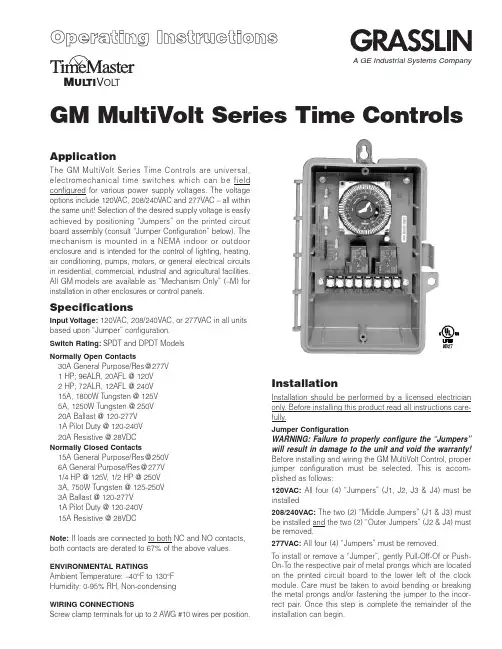
GM MultiVolt Series Time ControlsM UL TI V OL TApplicationThe G M MultiVolt Series Time Controls are universal,electromechanical time switches which can be field configured for various power supply voltages. The voltage options include 120VAC, 208/240VAC and 277VAC – all within the same unit! Selection of the desired supply voltage is easily achieved by positioning “Jumpers” on the printed circuit board assembly (consult “Jumper Configuration” below). The mechanism is mounted in a NEMA indoor or outdoor enclosure and is intended for the control of lighting, heating,air conditioning, pumps, motors, or general electrical circuits in residential, commercial, industrial and agricultural facilities.All G M models are available as “Mechanism Only” (–M) for installation in other enclosures or control panels.SpecificationsInput Voltage:120VAC, 208/240VAC, or 277VAC in all units based upon “Jumper” configuration.Switch Rating:SPDT and DPDT Models Normally Open Contacts30A General Purpose/Res @277V 1 HP; 96ALR, 20AFL @ 120V 2 HP; 72ALR, 12AFL @ 240V 15A, 1800W Tungsten @ 125V 5A, 1250W Tungsten @ 250V 20A Ballast @ 120-277V 1A Pilot Duty @ 120-240V 20A Resistive @ 28VDC Normally Closed Contacts15A General Purpose/Res @250V 6A General Purpose/Res @277V 1/4 HP @ 125V , 1/2 HP @ 250V 3A, 750W Tungsten @ 125-250V 3A Ballast @ 120-277V 1A Pilot Duty @ 120-240V 15A Resistive @ 28VDCNote:If loads are connected to both NC and NO contacts,both contacts are derated to 67% of the above values.ENVIRONMENTAL RATINGSAmbient Temperature: –40°F to 130°F Humidity: 0-95% RH, Non-condensingWIRING CONNECTIONSScrew clamp terminals for up to 2 AWG #10 wires per position.InstallationInstallation should be performed by a licensed electrician only. Before installing this product read all instructions care-fully.Jumper ConfigurationWARNING:Failure to properly configure the “Jumpers”will result in damage to the unit and void the warranty!Before installing and wiring the GM MultiVolt Control, proper jumper configuration must be selected. This is accom-plished as follows:120VAC:All four (4) “Jumpers” (J1, J2, J3 & J4) must be installed208/240VAC:The two (2) “Middle Jumpers” (J1 & J3) must be installed and the two (2) “Outer Jumpers” (J2 & J4) must be removed.277VAC:All four (4) “Jumpers” must be removed.To install or remove a “Jumper”, gently Pull-Off-Of or Push-On-To the respective pair of metal prongs which are located on the printed circuit board to the lower left of the clock module. Care must be taken to avoid bending or breaking the metal prongs and/or fastening the jumper to the incor-rect pair. Once this step is complete the remainder of the installation can begin.A GE Industrial Systems CompanyThis enclosure does not provide grounding between con-duits. When using non-metallic conduit or cable, connect the ground wires of all cables together with a wire nut. When metallic conduit is used, use grounding type bushings and a jumper wire between each conduit.Programming InstructionsElectromechanical ModelsSETTING THE TIME:Rotate the program dial gradually clockwise until the day of the week (7 day) and time of day on the outer dial is nearly aligned with the triangle marker at 2 o’clock position. Then set time to the minute by rotating minute hand clockwise.CAUTION: Do not rotate dial or minute hand counter-clock-wise.PROGRAMMING:The 24 hour model has trippers of 15minute increments, and a AM/PM indication on the outer dial.The 7 day model has trippers of 2 hour increments, and the outer dial shows the 7 days of the week and AM/PM for each day. Push the captive trippers outward for the time period(s)that the load is to be on (Normally open contacts closed).Manual Override : With the manual switch in the middle posi-tion, the time switch is in automatic mode and will switch at the programmed times. In the upper position “I”, the load is permanently ON. In the lower position, “O”, the load is per-manently OFF .BATTERY POWERED RESERVE (Quartz Models):In case of power failure, the built-in nickel-cadmium battery maintains the time of day for 7 days. During power outage relays are de-energized.P r i n t e d i n U S A 122U S 04.01Typical Wiring Diagrams—SPDTTypical Wiring Diagrams—DPDTNote:For outdoor locations, Raintight or wet location conduit hubs that comply with requirements of UL 514B (standard for fittings for conduit and outlet boxes) are to be used.1. Remove 2 screws retaining the interior cover panel and remove panel by prying out with a thin blade at the top.2. Select knockouts to be used. Remove the inner (1/2”)knockout by inserting a screwdriver in the slot and care-fully punch knockout loose. Remove slug. If the 3/4”knockout is required, remove the outer ring with pliersafter removing the 1/2” knockout. Smooth edges with knife if necessary.3. Place enclosure in desired mounting location and mark the three mounting holes.4. Drill holes for #10 screws, start screws in holes.5. Place enclosure over screws and tighten screws.6. Connect conduit hubs to conduit before connecting the hubs to the enclosure. After inserting hubs into enclosure,carefully tighten hub lock nut. Do not over-tighten.7. Install in accordance with all applicable National and Local code requirements.8. Replace interior cover panel and 2 screws.Note:To mount mechanism into an Intermatic enclosure (all except T7000 & T5000), remove 4 hex screws retaining the GM PCB assembly and remove from enclosure. Install in Intermatic enclosure in the same manner as the Intermatic mechanism was installed.GROUNDING :This enclosure is of plastic construction and does not require a ground connection and does not require bonding in pool applications.Timer and Load, Same Voltage120V Two Speed FanTimer and Load, Different Voltage120V Timer, 120V Load and 24V Load 120V Timer, 208/240/277V Load Double BreakField Wiring Timer Internal WiringGRASSLIN CONTROLS CORPORATION A GE Industrial Systems Company31 Industrial Ave. • Mahwah, New Jersey 07430Tel.: 201-825-9696 • Fax: 。

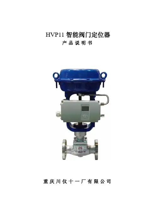
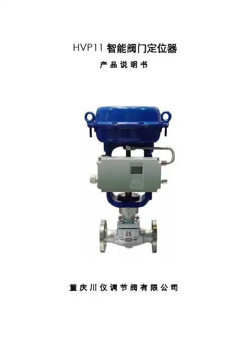
HVP11智能阀门定位器产品说明书重庆川仪十一厂有限公司用户须知1、本产品先上电,后供气源。
2、用户第一次使用前,必须检测安装位置,进行自动检测。
3、如果改变了安装位置,需要检测安装位置和进行自动检测。
4、严禁连接处漏气,用肥皂水检查连接处的气密性。
5、气源要求:a、气源应为清洁、干燥的空气,应无明显的油蒸汽、油和其它流体;b、气源应无明显的腐蚀性气体、蒸汽和油剂;c、气源中所含固体微粒数量应小于0.1g/m3,且微粒直径小于20um,含油量应小于10mg/ m3;d、工作压力下的气源露点应比定位器工作环境温度至少低10°C。
警告:执行机构气室无压力才准安装智能阀门定位器。
气源质量必须达到以上第5条的要求,特别是气源应干燥,否则会损坏定位器。
一、概 述HVP11本安型定位器是一种智能型的阀门定位器,该产品属国家“九·五”重点科技攻关项目,是现场总线仪表中《智能执行器专题》下的一个分专题。
它采用两线制传输(即电源、4~20mA模拟信号、双向数字通信信号同在两根线上传输)。
其工作原理与传统电—气阀门定位器截然不同,HVP智能阀门定位器与气动执行机构组成一个反馈控制回路,在这个控制回路中,显示的调节阀位置反馈信号作为被控制的变量,与给定信号值在微处理器中作比较,这两个信号的偏差通过主控板的输出口,发出不同长度的脉冲,控制I/P转换单元压力输出口的压力输出,从而驱动调节阀动作(如图1所示)。
气动调节阀带上HVP智能阀门定位器,能很好地克服摩擦力和阀芯上的不平衡力,提高调节阀的响应速度,使其定位更迅速、精确,特别适合振动频繁场所。
它不仅完全能替代传统的电—气阀门定位器,而且可直接接入HART协议网络系统。
用户可通过上位机读写它的工位号、设备号、产品序列号等基本设备管理信息,并可实时监视调节阀的动态信息(如调节阀全开、全闭等)。
可随时就地(用按钮、手持设定器)或通过上位机对它的控制参数进行调整和设定。
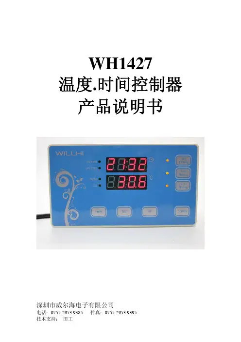
WH1427温度.时间控制器产品说明书深圳市威尔海电子有限公司电话:0755-2953 9385 传真:*************技术支持:田工①安装开口尺寸:温控功能:指示灯状态说明:WORK指示灯为工作指示灯,闪烁表示制冷或制热延时,长亮表示制冷或制热工作。
SET指示灯为设置指示灯,长亮表示在设置状态。
开启或关闭温控器:温控器通电后默认是开机状态。
在关机状态下按TIME键一次可开启温控器,在开机状态下,按住TIME键3秒以上,可关闭温控器。
◆设定控制温度:在待机状态下按SET键一次进入控制温度设置,按UP或DOWN键调整,按住UP或DOWN键三秒不放进入快速调整模式.再按SET键一次回到待机状态. 设置控制参数:按住SET和UP键三秒不放进入控制参数设置,按UP或DOWN键选择要调整的菜单,再按SET键一次进入相应的控制参数设置状态,按UP或DOWN键调整需要修改的控制参数,调整好后按TIME键退出,或系统延时5秒退出菜单代码说明:菜单代码详细说明 解释 单位 HC 制热/制冷 温控器工作模式设置 H=制热,C=制冷D 回差 开机和停机之间的温度差℃LS 设置下限 控制温度可设定的最小值℃HS 设置上限 控制温度可设定的最大值℃CA 温度较正 ℃PT 延时启动 最小开停机时间间隔 分钟AH 超高温报警 超高温报警 ℃AL 超低温报警 超低温报警 ℃◆温控器工作模式设置:温控器可以设定为制冷模式,也可以设定为加热模式。
当需要高于某个温度开启一个设备时,请设定为制冷模式,当需要高于某个温度关闭一个设备时,请设定为制热模式。
制冷模式:当测量温度值≥控制温度+回差时,启动输出,继电器吸合;当测量温度<控制温度时,关闭输出,继电器断开。
制热模式:当测量温度值≥控制温度时,关闭输出,继电器断开;当测量温度<控制温度-回差时,启动输出,继电器吸合。
设置举例:如果设为加热模式, 控制温度为25度,回差设为5, 那么当测量温度高于或等于25度时继电器断开,关闭输出.当温度低于20度时再接通继电器, 启动输出设置举例:如果设为制冷模式, 控制温度为25度,回差设为5, 那么当测量温度低于25度时继电器断开,关闭输出.当温度高于或等于30度时再接通继电器, 启动输出◆制冷、制热模式设定:按住SET和UP键不放超过3秒,进入菜单显示,屏幕出现"HC"代码时,按"SET" 键显示工作模式,再按“UP”或"DOWN"调整参数, C表示制冷模式;H表示制热模式.◆回差功能:回差设置限定了开机和停机之间的最大温度差。


鸿合科技集团HiteVision交互式电子白板用户培训手册(2010版)目录目录 (2)第一阶段硬件与软件的安装 (4)1.白板安装形式 (4)2、设备连接步骤 (4)3、软件安装步骤 (4)第二阶段基本功能 (9)第一节运行白板系统软件 (9)第二节主工具栏功能简介 (10)第三节交互电子白板的三个工作界面 (12)一.白板页面 (13)二.计算机界面 (13)三.屏幕批注页面 (13)第四节交互电子白板的三个常用工具栏 (13)一、主工具栏 (14)二、开始菜单 (14)三、功能面板 (16)第五节图形编辑 (17)一、选择对象 (17)二.移动对象 (18)三.改变图像尺寸 (18)四.改变图像方向 (18)第六节对象的清除 (18)第八节在白板页面中使用文本 (19)第九节使用特殊功能 (19)一、聚光灯工具 (19)二、抓图工具 (20)三、遮屏工具 (20)四、时钟/定时器工具 (20)五、窗口播放器工具 (20)六、屏幕放大器工具 (21)第十节手写识别功能 (21)第十一节专业教学工具 (22)一、量角器工具 (22)二、三角板工具 (22)三、直尺工具 (22)四、圆规工具 (23)五、几何画板 (23)第十二节计算机文档的批注 (23)第十三节用户管理 (24)第十四节白板页面的打开,存储和导出 (25)第三阶段课件制作 (26)PPT课件授课 (26)白板课件授课 (26)白板课件授课实例 (27)1、新课导入 (27)2、认识圆 (28)3、画圆 (29)4、小结 (29)第四阶段练习与测试 (30)自我检测测试 (30)第1章主工具栏 (30)第2章主工具栏的Start菜单 (31)第3章功能面板 (32)综合测试一............................................ 错误!未定义书签。
综合测试二............................................ 错误!未定义书签。
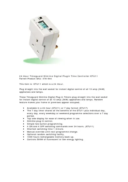
24 Hour Timeguard Slimline Digital Plugin Time Controller ETU11Farnell Product SKU: 478-544This item is: ETU11 which is a 24 Hour.Plug straight into the wall socket for instant digital control of all 13 amp (3kW) appliances and lamps.These Timeguard Slimline Digital Plug-in Timers plug straight into the wall socket for instant digital control of all 13 amp (3kW) appliances and lamps. Random feature makes your home or premises appear occupied.• Available in a 24 hour (ETU11) or 7 day format (ETU17)• The 7 day timer shares all the benefits of the ETU11 plus individual day, every day, every weekday or weekend programme selections over a 7 day period.• Top side display for ease of viewing when in use.• Slimline plug-in control.• Simple two button programming.• 4 ON and 4 OFF switching commands over 24 hours. (ETU11)• Shortest switching time 1 minute.• Manual override until next programme change.• Optional random switching facility.• 1000 hours rechargeable memory back-up.• Controls 500W of fluorescent or low energy lighting.Normal Operating ModeIn normal operation the PanelMaster willdisplay the correct time with the colon flashing. The output status will be shown by either ON or OFF on the display.1To Reset DisplayTo clear programmes from memory and reset the time controller press and hold down both buttons until the display goes blank. Release buttons and display will fill with its complete range of characters and then clear to show clock and hour digit flashing.You are now in the clock setting modeat the beginning of the programme sequenceBatteryThis product has a factory fitted rechargeable battery. If the time controller is left with its mains power switched off for more than 1month the display may go blank. In this case plug unit in, switch mains on, wait 30 minutes, and apply reset - see 1 before programming.ProgrammingOnly two setting buttons are provided <Change> and <Program>.During the programme mode the <Change> button is used to set the hour and minute times. Holding this button down achieves rapid selection of the hr and minute times. It is also used for changing the output status and selecting random mode during normal operation.The <Program> button is used to select the clock time and 4 ON/OFF programmes and to review them once set. Holding this button down achieves rapid selection of the next programmes or can be used as a quick exit from programme mode or programme review.Programming sequenceNote: Button pauses greater than 1 minute during programmingwill result in automatic return to the operating mode.2Setting Clock (after reset)iHour Setting - Press the <Change> button to advance the hour setting.Note: For rapid hour selections press and hold down <Change> button.ii Minute Setting - Press the <Program> button once to select the minutes - display shows clock symbol and minute digits flashing.Press the <Change> button to advance the minutes setting. Note: For rapid minute selection press and hold down <Change> button. (Note: 16 hrs shown as example of hrs set)iii Press <Program> button once - clock is now set and display shows ready for the first ON programme time with ON and hours digits flashing.3.To Set Programme ON/OFF Times (after clock setting)Programme 1 ON timeiPress <Change> button to advance the hour setting.Setting clockProgramme 1 ON Programme 1 OFF Programme 2 ON Programme 2 OFF Programme 3 ON Programme 3 OFF Programme 4 ON Programme 4 OFFOperating Modeii Press <Program> button once to select minute time - display shows minute digits and ON flashing. Press <Change> button to advance minute setting. (Note: 16 hrs shown as example of hours set).iii Press <Program> button once - the first ON time is now set and display shows ready for the first OFF programme time.iv Now set the hrs and minutes as before. v Repeat steps i to iv to set the remainder of the 3 ON/OFF times as required. Note: Any unused ON/OFF programme should be skipped until the display shows normal operating mode. Do not programme ‘0’s into unused programmes.IMPORTANT After setting a clock time which falls within a programmed ON period, the unit will not switch ON. Use the override facility to switch unit ON. After this the unit will operate normally to the programmes set.PROGRAMCHANGEETU 11PROGRAMME1 2 3 4RON::::::..........➔123456ETU11 Programming InstructionsEasy view 24hour digital clock/timer displayChange Button sets Hours and Minute times and self cancelling overrideProgramme Button used to select the clock time and the 4 ON/OFF programme times and to review them once setOutput Status showing unit either ON or OFFOFF1 2 3 41 2 3 41 2 3 4ON1 2 3 41 2 3 4ON1 2 3 4OFF 1 2 3 46.Cancelling ProgrammesAny ON/OFF programme can be cancelled by clearing its ON and OFF time. Follow step 5 and when into the ON or OFF programme to be cancelled press the <Change> buttonuntil the hour digits show --:then pressthe <Program> button to clear the programme. The display will show the hour and minute digits and ON or OFF flashing.7.Self Cancelling OverrideTo change the output status from ON to OFF or vice versa during normal operation press the <Change> button. The output status will change and indicate override is in operation by flashing.8.Random OperationIf the <Change> button is held down for 3 to 5 seconds in operating mode an R will appear at the left hand side of the display and the unit will turn on and off in a random fashion during programmed ON periods (max/min off/on time 10/31minutes). To cancel hold down button until the R disappears.SpecificationsOperating Temp:0°C to 35°COperating Voltage:220 - 240V AC 50HzSwitch Rating:240V AC 13 amp resistive (3Kw)5 amp inductive 2500W Filament 500W FluorescentBattery:Factory fitted rechargeable - 1000hrs back-up Not suitable for discharge lighting (eg. SON and Metal Halide)4.Programme ReviewTo fast review the set programmes or for quick exit to normal operating mode - press and hold the <Program> button.5.Initiating Programme ModeThis can be initiated any time during the normal operating mode.Press <Program> button and the Clock symbol, hrs and minutes symbols on the display will flash - this is review mode. Further pressing of the <Program> button will display the ON and OFF programmes in sequence. If any change to programmes isrequired press <Change> button to initiate programme mode and then follow steps 2 and 3.78910ImportantThis time controller is recommended for general domesticappliances up to 13 amp resistive (3Kw) or 5 amp inductive rating3 Year GuaranteeIn the unlikely event of this product becoming faulty, due to defectivematerial or manufacture, within 3 years of the date of purchase, please return it to your supplier with proof of purchase and it will be replaced free of charge.Should you encounter any difficulty please contact our helpline on 020 8450 0515.ON 1 2 3 4HELPLINE020-8450-0515For a product brochure please contact:Timeguard Ltd.Victory Park, 400 Edgware Road,London NW2 6ND Tel: 020-8452-1112************************Designed & Manufactured in the U.K. 67-058-22 (ISS 2)24 H O U R S L I M L I N E D I G I T A L T I M E C O N T R O L L E RCat No. ETU11。
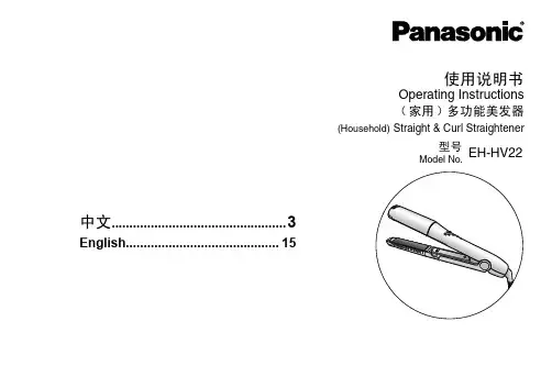
设置和操作HV-2000C 喷射点胶机 控制器Diaphragm-Jet ™ 技术ZH用于工业环境中粘性材料的非接触式点胶工艺的控制。
仅供专业用途。
重要的安全说明请在使用该设备之前,阅读本手册内所有的警告和说明内容,以及所有的相关手册内容。
应妥善保存这些说明。
3A6157APROVEN QUALITY. LEADING TECHNOLOGY.相关手册 (4)安全指南 (5)1.介绍与规格 (6)1.1Advanjet HV-2000/2000C 概览 (6)1.2HV-2000C 控制器规格 (7)1.3技术协助 (7)1.4HV-2000C 控制器规格 (8)1.5HV-2000C 前部和北部特征 (9)2.安装和设置 (10)2.1实际放置 (10)2.2气动系统 (10)2.3电气接口 (11)2.4输入/输出连接 (12)3.HV-2000C 控制器前面板的使用 (13)3.1喷射压力和流体压力调节器 (13)3.2温度控制器 (14)3.3触发按钮和 LED 灯 (15)3.4LCD 显示屏和选择按键 (16)3.5在前面板进行喷射设置 (16)3.6前面板按键特殊用法 (18)4.RS-232 通讯 (19)4.1RS-232 连接器针脚 (19)4.2更改默认 RS-232 设置 (20)5.ADVANJET 软件 (21)5.1软件的安装与启动 (21)5.2设置菜单 (22)5.3从软件内运行程序 (25)6.计时配方 (26)6.1计时配方参数 (26)6.2编程计时配方 (27)6.3胶滴模式的编程 (29)一次点胶一滴 (29)多种胶滴尺寸点胶 (29)6.4线型模式的编程 (30)第 1 种方法:采用脉冲模式点胶成线 (30)第 2 种方法:采用连续模式点胶成线 (30)第 3 种方法:在 X-Y 移动过程中喷射点胶成线 (31)7.ADVANJET 控制器命令 (ACC) (32)7.1RS-232 接口 (32)7.2命令格式 (32)7.3配方计时命令 (33)7.4喷射命令 (35)7.5加热器命令 (37)第 2 页,共 59页Advanjet HV-2000C 喷射点胶机控制器的设置和操作3A6157A7.6输出命令 (38)APPENDIX 1:首滴补偿功能 (39)Appendix 1-1:背景知识 (39)Appendix 1-2:首滴补偿的计算 (39)Appendix 1-3:脉冲模式下的首滴补偿 (40)Appendix 1-4:连续模式下的首滴补偿 (42)APPENDIX 2:温度控制器出厂设置 (43)APPENDIX 3:数显压力表 (44)Appendix 3-1:规格 (44)Appendix 3-2:部件名称和功能 (45)Appendix 3-3:连接和输入/输出线路 (46)Appendix 3-4:操作模式选择 (47)Appendix 3-5:操作模式选择 (48)Appendix 3-6:调节 (49)Appendix 3-7:其它功能和错误显示 (50)APPENDIX 4:输入/输出连接器 (51)Appendix 4-1:HD26 针脚配置 (51)Appendix 4-2:可配置输入/输出 DIO0-DIO31 的接线图 (54)Appendix 4-3:缓存型数/模转换器输入的接线图 (55)Appendix 4-4:数/模转换器输出的接线图 (56)Appendix 4-5:压力报警输入/输出电路的接线图 (57)APPENDIX 5:更换 24V 驱动板熔断器 (58)GRACO 标准保修 (59)3A6157A Advanjet HV-2000C 喷射点胶机控制器的设置和操作第 3 页,共 59页相关手册相关手册可前往获取。
SummaryEngineers are faced with the challenge of reducing system costs, increasing performance and effi ciency while balancing that with increasing application requirements. This is especially true for newer LED lighting and battery charging applications. PIC12F(HV)752 microcontrollers brings the next generation analog and digital peripherals, to the popular Mid-Range architecture. These MCUs not only fi t in various general purpose applications, but are also well suited for specifi c applications like LED lighting, ballast control, battery chargers and power supplies.The PIC12F752 is an 8-pin MCU that offers 1.75 KB of self read-write program memory, 64B of RAM, 10-bit ADC, fast comparators, complementary waveform generator, 5-bit DAC, capture compare and PWM module and multiple other features and peripherals to make it relevant for wide variety of applications. The PIC12HV752 MCU, which is the high voltage variant, incorporates a shunt regulator that allows operation from 2V to an unspecifi ed user-defi ned maximum voltage level. This high voltage variant is ideal for cost sensitive applications with high voltage power rails.Key Features■ Mid-Range PIC® ArchitectureBased on Microchip’s mature 8-bit core providing POR, BOR, Interrupts and WDT to enable highly effi cient circuits.■ Self Read-Write Flash Program MemoryServes as a low cost alternative to Data EE. This is very useful when an application requires remote updates, or needs to store system data or look up tables.■ Analog PeripheralsThe 4 channel, 10-bit ADC can be used to implement various sensors and mTouch™ applications. Fast 20 ns comparators can be used to implement effi cient switching circuits.■ Complementary Waveform GeneratorProvides non-overlapping complementary waveform for various inputs like comparators, PWM; while affording enhanced features like dead band control, auto shutdown, auto reset, phase control and blanking control.■ Digital to Analog Converter The true 5-bit DAC offers the fl exibility of output voltage range selection. The V DD or the external V REF pin can act as the reference to the circuit.M i c r o ch i p T e c h n o l o g y I n c o r p o r a t e dPIC12F(HV)752 MicrocontrollersBringing advanced analog and digital peripherals to 8-pin MCUs.■ Capture Compare and PWMThis module can be utilized to implement variety of motor control and lighting applications.■ High Voltage V DD Support (HV variants only)Allows for connection to an application that has high voltage rails, without the need of an external regulator. It promotes component cost and board area savings.Application Examples ■ LED lighting ■ Lamp ballast■ Automotive head and tail lamps■High Intensity Discharge (HID) lighting ■ LCD backlighting■ Power factor correction■ Battery monitoring and charging ■ Signal conditioning■ Flyback AC-to-DC converter ■ Low voltage AC-to-DC converter ■ Synchronous DC-to-DC converter■ Many other general purpose applications Development Made EasyThe PIC12F(HV)752 family provides a low-cost development experience from code creation, to integration into the end application.■ Develop your Code – MPLAB®IDE with integratedHI-TECH C® compiler allows designers to develop code and simulate their application with zero initial investment. ■ Program and Debug – The PIC12F752 family supports In-Circuit Debug functionality without the use of an additional header. Connect the PICkit™ 3 Debugger or MPLAB ICD 3 In-Circuit Debugger to get started.Information subject to change. The Microchip name and logo, the Microchip logo, MPLAB and PIC are registered trademarks and ICSP , mTouch, PICDEM and PICkit are trademarks of Microchip Technology Incorporated in the U.S.A. and other countries. All other trademarks mentioned herein are property of their respective companies. © 2011, Microchip Technology Incorporated. All Rights Reserved.Printed in the U.S.A. 2/11 DS41562A*DS41562A*Visit our web site for additional product information and to locate your local sales office.Microchip Technology Inc. • 2355 W. Chandler Blvd. • Chandler, AZ 85224-6199/8bitAdditional Information■ PIC12F(HV)752 Data Sheet (Available Q2’11)■ Designing with HV Microcontrollers , AN1035■ 8-bit PIC® Microcontroller Solution Brochure , DS39630■ Corporate Focus Product Selector Guide , DS01308■ Quick Guide to Microchip Development Tools Brochure ,DS51894Device I/O Flash (KB)Data RAM (Bytes)10-bit ADC ch Comp CWG DAC CCP Timers (8-bit/16-bit)Operating Voltage Pins Packages PIC12F7526 1.75644215-bit 13/12V-5.5V 8PDIP , SOIC, 3x3 DFN PIC12HV75261.75644215-bit13/12-User defi ned8PDIP , SOIC, 3x3 DFNLearn more at:/8bitSample InformationOn-line Sampling: Part Number Development Tool DescriptionDV164131PICkit™ 3 Debug Express In-Circuit Debugger/Programmer uses in-circuit debugging logic incorporated into eachchip with Flash memory to provide a low-cost hardware debugger and programmer.DV164035MPLAB®ICD 3 In-Circuit DebuggerCost effective high-speed hardware debugger/programmer for Flash Digital Signal Controller (DSC) and microcontroller (MCU) devices.DM163035PICDEM™ Lab Development KitComprehensive development platform for virtually all of Microchip’s Flash-based 6-, 8-, 14-, 18- and 20-pin, 8-bit PIC® MCUs. Geared toward students and fi rst-time users, the kit supplies fi ve of the most popular 8-bit MCUs and a host of discrete components used to create a number of commonly used circuits.DM164120-1PICkit™ 2 Low Pin Count Demo Board (8/14/20 pins)Small demo board with a PIC16F690 MCU on-board and a small prototype area. Use this with the PICkit™ 2 Starter Kit to program code via the 6-pin ICSP™ header on the board. The kit also includes two bare PCB boards for those interested in customizing their development.DM163014PICDEM™ 4 Demonstration BoardDemonstration and evaluation board for the 8-, 14- and 18-pin general purpose family of products with power management features. Includes pre-programmed PIC18F1320 and PIC16F627A Flash-based MCUs, which feature nanoWatt Technology.DV007004MPLAB® PM3 Universal Device ProgrammerOperates with a PC or as a stand-alone unit, and programs Microchip’s entire line of PIC devices as well as the latest dsPIC30F DSC devices.。
HPW-SM11-5型风冷热泵单压机热水控制器,综合了系统优化、节能、方便用户使用等诸多优点而设计成为目前国内最先进的智能控制仪器。
它可以根据用户需要和实际的现场情况有选择地采用一种功能或几种功能的控制方式,并支持二次循环泵选用变频控制,整个热水供应系统完整、节能、人性化。
该控制器主要完成对蓄热循环泵、压缩机、风机、化霜电热器、辅助电热器、补水泵、回水阀的控制,同时对键盘、显示器进行管理并对输入信号进行采样,查询各设备的工作状态、以及故障分析和报警,并具有远程监控的功能及实时时钟控制功能。
一. 主要性能指标1-1.输入模拟量:①进水温度 -30℃----+95℃分辩率0.2℃②出水温度 -30℃----+95℃分辩率0.2℃③冷排温度 -30℃----+95℃分辩率0.2℃④环境温度 -30℃----+95℃分辩率0.2℃⑤蓄热水箱温度 -30℃----+95℃分辩率0.2℃⑥二次回水温度 -30℃----+95℃分辩率0.2℃1-2.输入开关量:①上/下班开关②靶流开/关信号③高压保护④低压保护⑤排气温度保护⑥化霜电热器超温保护⑦蓄热水箱高水位⑧蓄热水箱低水位⑨二次循环泵启/停信号1-3.输出控制对象:①压缩机②风机1③风机2④化霜电热器⑤辅助电热器⑥蓄热循环泵⑦补水泵⑧报警⑨二次回水电磁阀二.主要技术特点●采用了多事件触发记忆,优化排序的程序结构,使机组运行及管理更加完善,更具有人性化特点。
●除霜过程采用了多变量、多模式自修正的智能控制,使除霜更加有效,提高了机组运行效率。
●控制参数可在线设定,具有断电保护功能,停电后常数不丢失。
●各设备运行状态采用循环显示方式,键盘中断,查找迅速,显示稳定。
●正常工作时,显示机组的参数及工作状态,一旦发生故障,就自动显示报警参数、状态,以方便用户维护。
三.控制器结构及电气连接● CZ1与变压器~220V连接,CZ2连接变压器输出● JD1端子(强电端子)输出给设备的继电器,板上标有压缩机、风机1、风机2、化霜电热器、辅助电热器、蓄热循环泵、补水泵、报警、二次热水循环电磁阀的输出接端子。
基于Profibus_DP总线组态配置文档深圳市禾望电气股份有限公司2020-07-18目录1.平台搭建 (3)1.1通讯协议规定 (3)2.变频器参数配置 (4)3.PLC组态配置 (6)摘要:本文档基于西门子S7-300系列PLC 作为控制器,展示HD2000/HV500系列的变频器集成在Profibus_DP 现场总线作为从站的组态配置过程,可作为自动化系统工程师和技术支持工程师在系统集成及产品应用中的指导手册。
减轻产品应用相关人员的手册、文档阅读量等繁重工作,提高自动化系统工程师和客服工程师工作效率。
1.平台搭建本文档的测试平台由西门子S7-300的PLC 作为控制器,从站为HD2000系列的工程型变频器控制器HCU20(HV500通用高性能变频器类似,仅变频器侧几个参数号配置差异。
仅仅是HD2000、HV500的过程字缓冲区参数号不同。
通信卡参数配置均在20组参数,过程字配置均在25组参数,选件卡配置在系统配置参数组),总线采用Profibus_DP ,如图1.1所示,系统测试平台的架构。
主站CPU 314-2PN/DPHCU20逆变单元从站Profibus_DP 光纤电机图1.1HD2000自动化系统架构1.1通讯协议规定为展示系统组态的过程,本文档规定自动化协议如表1.1所示:系统组态配置之前,先将笔记本电脑的IP 地址修改到PLC 和HCU20同一个网段,保证笔记本电脑可正常与PLC 、HCU20控制器通讯。
图1.2 修改电脑IP 地址2.变频器参数配置为确保变频器与PLC可通过Profibus_DP总线协议进行通讯,必须正确配置HD2000与Profibus_DP通讯相关的通讯参数配置,参数配置完毕,固化参数到控制器HCU20。
本文档采用的是禾望电气新一代HCU20作为控制器,作为测试平台的。
打开后台软件“hopeinsight”,然后通过连接HCU20控制器。
1)更新HCU20控制器的拓扑结构,打通HCU20控制器与功率单元的映射关系,更新拓扑的过程如图2.1所示,把S-46.04设置为“1-自动配置”,S-46.07设置为“1-自动更新拓扑”,在HCU20与功率单元正确连接的情况下,系统将自动更新拓扑,更新完成后,上述参数恢复成“0”;图2.1 更新拓扑2)配置拓展卡参数,本案例选择Profibus_DP总线协议,控制单元“S-01.30”配置成“1-Anybus通讯模块”;图2.2 扩展卡选择3)配置总线协议与数据映射建立,参数S-20.01配置“1-ABCC模块”,S-20.03可确认当前通讯模块的状态,S-20.18/S-20.19可确认当前变频器使用的通讯方式。