CAN基础培训-物理层
- 格式:pdf
- 大小:947.62 KB
- 文档页数:28
CAN物理层-CANphysicallayerCAN物理层-CAN physical layer作者:admin 添加时间:2012-05-05 18:53:30 浏览:474●?位编码●?位定时和同步●?数据速率和总线长度的相关性●?物理介质●?⽹络拓扑●?总线访问●?物理层标准ISO 11898-2 (⾼速)ISO 11898-3 (容错)SAE J2411 (单线)ISO 11992 (点对点)其它控制器局域⽹(CAN)协议在OSI模型(共有七个层)中定义了数据链路层和物理层。
国际标准组织(ISO)定义了包含CAN规范以及部分物理层的标准:物理信令,由位编码和解码(不归零制,简称NRZ)以及位定时和同步组成。
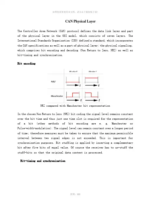
1. 位编码NRZ与曼彻斯特编码法相⽐较在选定的不归零制(NRZ)位编码中,信号电平在位时间内保持恒定,因此仅需要⼀个时间间隙来表⽰位M位编码的其它⽅法例如:曼彻斯特编码法或脉冲宽度调制)。
信号电平可以在较长时段内保持恒定;因此必须采取措施以确保不超过两个信号沿之间的最⼤允许时间间隔。
这对于实现同步⾮常重要。
通过在相等值的五位数后⾯插⼊互补位来应⽤位填充。
当然,接收器不能填⼊填充位,这样才能处理原始数据内容。
2. 位定时和同步在位级(OSI层1,物理层)上,CAN使⽤同步位传输。
这固然加⼤了发送容量,但同时也意味着要求更复杂的位同步⽅法。
⼀旦接收到带有每个字符的起始位,便开始在⾯向字符的传输(⾮同步)中执⾏位同步,这时同步传输协议的帧开头仅有⼀个起始位。
为了能使接收器正确读取消息,需要连续进⾏再同步。
因此请在位时间间隔内,在标称采样点的前后插⼊相位缓冲段。
CAN是可调节的逐位仲裁总线访问协议。
信号从发送到接收应答必须在⼀个位时间内完成。
为了实现同步,传输延迟环节,需要留出传播延迟段。
传播延迟段考虑了总线上的信号传播以及因发送和接收节点⽽导致的信号延迟。
请区分两种类型的同步:帧起始处的硬同步与帧内的再同步。
文库资料 ©2016 Guangzhou ZHIYUAN Electronics Stock Co., Ltd.
文章源自ZLG 致远电子,转载或引用请注明出处
1 CAN 总线基本物理层和链路层分析实验
一、实验目的
1、熟悉CANScope 软件,掌握CANScope 的操作。
2、利用CANScope 了解基本物理层和链路层的分析方法。
二、实验步骤
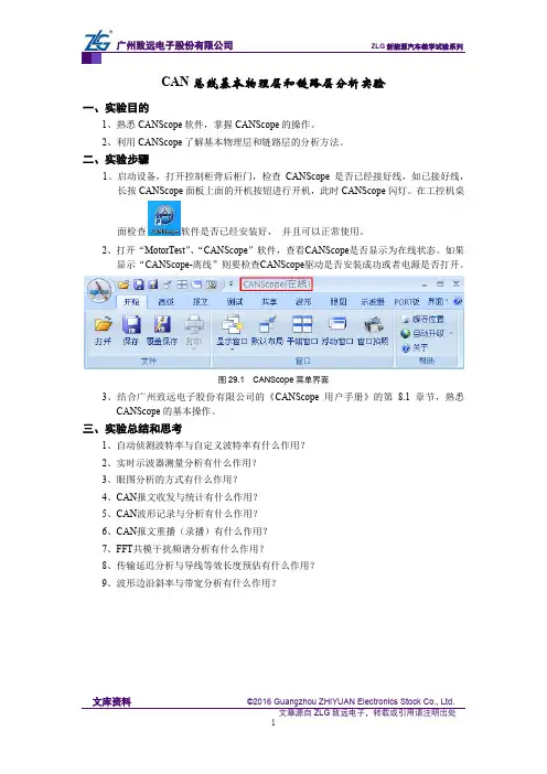
1、启动设备,打开控制柜背后柜门,检查CANScope 是否已经接好线,如已接好线,长按CANScope 面板上面的开机按钮进行开机,此时CANScope 闪灯。
在工控机桌面检查软件是否已经安装好, 并且可以正常使用。
2、打开“MotorTest ”、“CANScope ”软件,查看CANScope 是否显示为在线状态。
如果显示“CANScope-离线”则要检查CANScope 驱动是否安装成功或者电源是否打开。
图29.1
CANScope 菜单界面
3、结合广州致远电子股份有限公司的《CANScope 用户手册》的第8.1章节,熟悉CANScope 的基本操作。
三、实验总结和思考
1、自动侦测波特率与自定义波特率有什么作用?
2、实时示波器测量分析有什么作用?
3、眼图分析的方式有什么作用?
4、CAN 报文收发与统计有什么作用?
5、CAN 波形记录与分析有什么作用?
6、CAN 报文重播(录播)有什么作用?
7、FFT 共模干扰频谱分析有什么作用?
8、传输延迟分析与导线等效长度预估有什么作用?
9、波形边沿斜率与带宽分析有什么作用?。
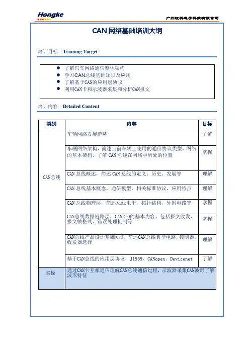
[导读]控制器局域网(CAN)标准不断发展,正用于车载和工业网络之外的许多新应用。
支持它的微处理器变得普遍且价格低廉,并且开源协议栈让其非常容易访问,同时也容易添加至新系统。
控制器局域网(CAN)标准不断发展,正用于车载和工业网络之外的许多新应用。
支持它的微处理器变得普遍且价格低廉,并且开源协议栈让其非常容易访问,同时也容易添加至新系统。
有许多CAN板可用于BeagleBone (Capes)、Stellaris (BoosterPacks)、Arduino (Shields)和其他微处理器开发平台。
当设计人员的系统上电却不能工作时,应该怎么办呢?本文为您介绍一种对CAN物理层进行调试的较好工程方法。
我们将介绍基础调试步骤,并说明一个CAN物理层应有的性能,以及找出问题的一些小技巧。
调试基础知识ISO11898-2和ISO11898-5规范详细说明了高速CAN物理层即收发器。
掌握CAN物理层的基础知识以后,利用简单的调试工具便可迅速地找出常见问题。
所需的基本实验室工具为示波镜、数字万用表(DMM)和一个电源。
如果想要深入了解问题,则需要更高精度和更复杂的工具。
这种问题已非本文讨论的范畴,但是这里介绍的基础知识可帮助确定问题所属类别,以及进一步调试所需的其他工具。
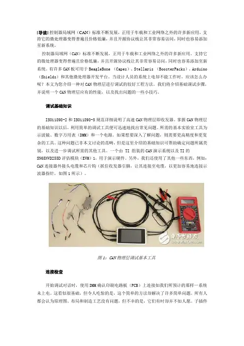
一个由 TI 组装的CAN演示系统以及TI的SN65NVD255D评估模块(EVM)1,用于演示硬件。
另外,我们还使用了其他一些东西,例如:CAN连接器外接头电缆和芯片钩(抓住收发器引脚,让其连接至电缆,以更加容易地连接示波器指针,如图1所示)。
图1:CAN物理层调试基本工具连接检查开始调试对话时,使用DMM确认印刷电路板(PCB)上连接如我们所预计的那样—系统未上电。
这看似很基础,但令人吃惊的是,这个简单的方法却解决了许多简单问题。
所有人都会认为原理图、布局和制造工艺没有问题,但不幸的是,它们有时却并不如人愿。
子插件板位置错误、虚焊和错误端接或者连接的电缆,都是一些常见问题。

CAN Physical LayerThe Controller Area Network (CAN) protocol defines the data link layer and part of the physical layer in the OSI model, which consists of seven layers. The International Standards Organization (ISO) defined a standard, which incorporates the CAN specifications as well as a part of physical layer: the physical signaling, which comprises bit encoding and decoding (Non Return to Zero, NRZ) as well as bit-timing and synchronization.Bit encodingNRZ compared with Manchester bit representationIn the chosen Non Return to Zero (NRZ) bit coding the signal level remains constant over the bit time and thus just one time slot is required for the representation of a bit (other methods of bit encoding are e. g. Manchester or Pulse-width-modulation). The signal level can remain constant over a longer period of time; therefore measures must be taken to ensure that the maximum permissible interval between two signal edges is not exceeded. This is important for synchronization purposes. Bit stuffing is applied by inserting a complementary bit after five bits of equal value. Of course the receiver has to un-stuff the stuff-bits so that the original data content is processed.Bit-timing and synchronizationNominal bit-timeOn the bit-level (OSI layer 1, physical layer) CAN uses synchronous bit transmission. This enhances the transmitting capacity but also means that a sophisticated method of bit synchronization is required. While bit synchronization in a character-oriented transmission (asynchronous) is performed upon the reception of the start bit available with each character, a synchronous transmission protocol there is just one start bit available at the beginning of a frame. To enable the receiver to correctly read the messages, continuous resynchronization is required. Phase buffer segments are therefore inserted before and after the nominal sample point within a bit interval.The CAN protocol regulates bus access by bit-wise arbitration. The signal propagation from sender to receiver and back to the sender must be completed within one bit-time. For synchronization purposes a further time segment, the propagation delay segment, is needed in addition to the time reserved for synchronization, the phase buffer segments. The propagation delay segment takes into account the signal propagation on the bus as well as signal delays caused by transmitting and receiving nodes.Two types of synchronization are distinguished: hard synchronization at the start of a frame and resynchronization within a frame.•After a hard synchronization the bit time is restarted at the end of the sync segment. Therefore the edge, which caused the hard synchronization, lies within the sync segment of the restarted bit time.•Resynchronization shortens or lengthens the bit time so that the sample point is shifted according to the detected edgeThe device designer may program the bit-timing parameters in the CAN controller by means of the appropriate registers.Interdependency of data rate and bus lengthDepending on the size of the propagation delay segment the maximum possible bus length at a specific data rate (or the maximum possible data rate at a specific bus length) can be determined. The signal propagation is determined by the two nodes within the system that are farthest apart from each other. It is the time that it takes a signal to travel from one node to the one farthest apart (taking into account the delay caused by the transmitting and receiving node), synchronization and the signal from the second node to travel back to the first one. Only then can the first node decide whether its own signal level (recessive in this case) is the actual level on the bus or whether it has been replaced by the dominant level by another node. This fact is important for bus arbitration.Some modern transceivers support no low data rates. Therefore on acquisition of transceivers the maximal required network length must be considered.Physical mediaThis clause is most interesting for system designers.The basis for transmitting CAN messages and for competing for bus access is the ability to represent a dominant and a recessive bit value. This is possible for electrical and optical media so far. Also powerline and wireless transmission is possible.For electrical media the differential output bus voltages are defined in ISO 11898-2 and ISO 11898-3, in SAE J2411, and ISO 11992 (see below).With optical media the recessive level is represented by "dark" and the dominant level by "light".The physical media most commonly used to implement CAN networks is a differentially driven pair of wired with common return. For vehicle body electronics single wire bus lines are also used. Some efforts have been made to develop a solution for the transmission of CAN signals on the same line as the power supply.The parameters of the electrical medium become important when the bus length is increased. Signal propagation, the line resistance and wire cross sections are factors when dimensioning a network. In order to achieve the highest possible bit rate at a given length, a high signal speed is required. For long bus lines thevoltage drops over the length of the bus line. The wire cross section necessary is calculated by the permissible voltage drop of the signal level between the two nodes farthest apart in the system and the overall input resistance of all connected receivers. The permissible voltage drop must be such that the signal level can be reliably interpreted at any receiving node.The consideration of electromagnetic compatibility and choice of cables and connectors belongs also to the tasks of a system integrator.assumed line length 100 mSpecific signal propagation time (ns/m)Maximum bit rate (kbit/s)5.0805.5736.0676.5627.058Network topologyThis clause is most interesting for system designers.Electrical signals on the bus are reflected at the ends of the electrical line unless measures against that have been taken. For the node to read the bus level correctly it is important that signal reflections are avoided. This is done by terminating the bus line with a termination resistor at both ends of the bus and by avoiding unnecessarily long stubs lines of the bus. The highest possible product of transmission rate and bus length line is achieved by keeping as close as possible to a single line structure and by terminating both ends of the line. Specific recommendations for this can be found in the according standards (i.e. ISO 11898-2 and -3).It is possible to overcome the limitations of the basic line topology by using repeaters, bridges or gateways. A repeater transfers an electrical signal from one physical bus segment to another segment. The signal is only refreshed and the repeater can be regarded as a passive component comparable to a cable. The repeater divides a bus into two physically independent segments. This causes an additional signal propagation time. However, it is logically just one bus system.A bridge connects two logically separated networks on the data link layer (OSIlayer 2). This is so that the CAN identifiers are unique in each of the two bus systems. Bridges implement a storage function and can forward messages or parts thereof in an independent time-delayed transmission. Bridges differ from repeaters since they forward messages, which are not local, while repeaters forward all electrical signals including the CAN identifier.A gateway provides the connection of networks with different higher-layer protocols. It therefore performs the translation of protocol data between two communication systems. This translation takes place on the application layer (OSI layer 7).Bus accessThe connection between a CAN controller chip and a two-wire differential bus a variety of CAN transceiver chips according to different physical layer standards are available (see below ISO 11898-2 and -3, etc.).This interface basically consists of a transmitting amplifier and a receiving amplifier (transceiver = transmit and receive). Aside from the adaptation of the signal representation between chip and bus medium the transceiver has to meet a series of additional requirements. As a transmitter it provides sufficient driver output capacity and protects the on-controller-chip driver against overloading. It also reduces electromagnetic radiation. As a receiver the CAN transceiver provides a defined recessive signal level and protects the on-controller-chip input comparator against over-voltages on the bus lines. It also extends the common mode range of the input comparator in the CAN controller and provides sufficient input sensitivity. Furthermore it detects bus errors such as line breakage, short circuits, shorts to ground, etc. A further function of the transceiver can also be the galvanic isolation of a CAN node and the bus line.Physical layer standardsISO 11898-2 high speedISO 11898-2 is the most used physical layer standard for CAN networks. It describes the bus access unit (implemented as CAN high-speed transceiver) functions as well as some medium-dependent interface features.In this standard the data rate is defined up to 1 Mbit/s with a theoretically possible bus length of 40 m at 1 Mbit/s. The high-speed standard specifies a two-wire differential bus whereby the number of nodes is limited by the electrical busload. The characteristic line impedance is 120 Ohm, the common mode voltage ranges from -2 V on CAN_L to +7 V on CAN_H. The nominal specific propagation delay of the two-wire bus line is specified at 5 ns/m. All these figures are valid only for a 1 Mbit/s transfer rate and a maximum network length of 40 m.In order to achieve physical compatibility all nodes in the network must use the same or a similar bit-timing. For automotive applications the SAE published the SAE J2284 specification. For industrial and other non-automotive applications the system designer may use the CiA 102 recommendation. This specification defines the bit-timing for rates of 10 kbit/s to 1 Mbit/s. It also provides recommendations for bus lines and for connectors and pin assignment.ISO 11898-3 fault-tolerantAn alternative form of bus interfacing and arrangement of bus lines is specified in ISO 11898-3 (fault-tolerant CAN). This standard is mainly used for body electronics in the automotive industry. Since for this specification a short network was assumed, the problem of signal reflection is not as important as for long bus lines. This makes the use of an open bus line possible.This means low bus drivers can be used for networks with very low power consumption and the bus topology is no longer limited to a linear structure. It is possible to transmit data asymmetrically over just one bus line in case of an electrical failure of one of the bus lines.ISO 11898-3 defines data rates up to 125 kbit/s with the maximum bus length depending on the data rate used and the busload. Up to 32 nodes per network are specified. The common mode voltage ranges between -2 V and +7 V. The power supply is defined at 5 V.Transceiver chips, which support this standard, are available from several companies. The fault-tolerant transceivers support the complete error management including the detection of bus errors and automatic switching to asymmetrical signal transmission.SAE J2411 single wireThe single-wire standard SAE J2411 is also for CAN network applications with low requirements regarding bit rate and bus length. The communication takes place via just one bus line with a nominal data rate of 33,3 kbit/s (83,3 kbit/s in high-speed mode for diagnostics). The standard defines up to 32 nodes per network. The main application area of this standard is in comfort electronics networks in motor vehicles.An unshielded single wire is defined as the bus medium. A linear bus topology structure is not necessary. The standard includes selective node sleep capability, which allows regular communication to take place among several nodes while others are left in a sleep state. Transceivers for this standard are available, too.ISO 11992 point-to-pointAn additional approach to using CAN low-speed networks with fault-tolerant functionality is specified in the ISO 11992 standard. It defines a point-to-point connection for use in e.g. towing vehicles and their trailers. For one vehicle with one trailer, a point-to-point connection is defined. For one vehicle with two trailers, a daisy-chain connection is defined. The nominal data rate is 125 kbit/s with a maximum bus line length of 40 m. The standard defines the bus error management and the supply voltage (12 V or 24 V). An unshielded twisted pair of wires is defined as the bus medium.OthersNot standardized are fiber-optical transmissions of CAN signals. Due to the directed coupling into the optical media, the transmitting and receiving lines must be provided separately. Also, each receiving line must be externally coupled with each transmitting line in order to ensure bit monitoring. A star coupler can implement this. The use of a passive star coupler is possible with a small number of nodes, thus this kind of network is limited in size. The extension of a CAN network with optical media is limited by the light power, the power attenuation along the line and the star coupler rather than the signal propagation as in electrical lines.Advantages of optical media are emission- and immission-free transmission andcomplete galvanic decoupling. The electrically neutral behavior is important for applications in explosive or electromagnetically disturbed environments.CAN总线物理层控制局域网(CAN)协议决定数据链路层和在OSI模式中部分物理层。
1、物理层一般要求1.1 物理层物理层实现网络中电控单元(ECU)的电连接。
ECU 的数目限制于总线线路的负载承受能力。
根据本部分的电气参数定义,在特定网段上ECU 的最大数目定为30。
1.2 物理介质物理介质为屏蔽双绞线。
双绞线特性阻抗为120Ω,电流对称驱动。
两条线分别命名为CAN_H 和CAN_L。
相应ECU 的管脚引线也分别用CAN_H 和CAN_L 来表示。
第三条连接屏蔽终端的线用CAN_SHLD 表示。
1.3 差动电压CAN_H和CAN_L相对于每个单独ECU地的电压有VCAN_H和VCAN_L 。
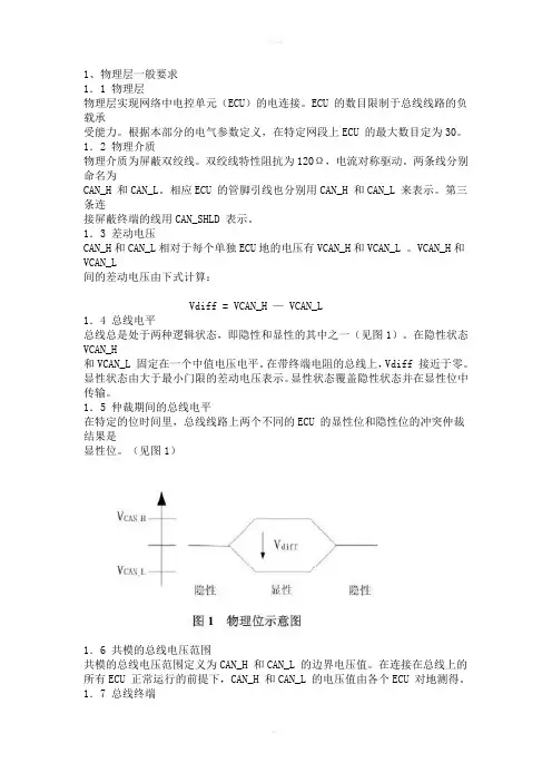
VCAN_H和VCAN_L间的差动电压由下式计算:Vdiff = VCAN_H — VCAN_L1.4 总线电平总线总是处于两种逻辑状态,即隐性和显性的其中之一(见图1)。
在隐性状态VCAN_H和VCAN_L 固定在一个中值电压电平。
在带终端电阻的总线上,Vdiff 接近于零。
显性状态由大于最小门限的差动电压表示。
显性状态覆盖隐性状态并在显性位中传输。
1.5 仲裁期间的总线电平在特定的位时间里,总线线路上两个不同的ECU 的显性位和隐性位的冲突仲裁结果是显性位。
(见图1)1.6 共模的总线电压范围共模的总线电压范围定义为CAN_H 和CAN_L 的边界电压值。
在连接在总线上的所有ECU 正常运行的前提下,CAN_H 和CAN_L 的电压值由各个ECU 对地测得。
1.7 总线终端在线路的两个末端上,必须接有负载电阻R 终结L。
RL 不得放置在ECU 中,以避免其中一个ECU 断线,总线将失去终端(见图2)。
1.8 内部电阻ECU 的内部电阻Rin 为隐性位状态,ECU 和总线线路断开下的CAN_H(或CAN_L)和ECU 地之间的电阻值。
(见图3)。
1.9 差动内部电阻ECU 的差动内部电阻Rdiff 为隐性位状态,ECU 和总线线路断开下的CAN_H 和CAN_L间的电阻值。
(见图4)。
1.10 内部电容ECU 的内部电容Cin 为隐性位状态,ECU 和总线线路断开下的CAN_H(或CAN_L)和ECU 逻辑地之间的电容值。
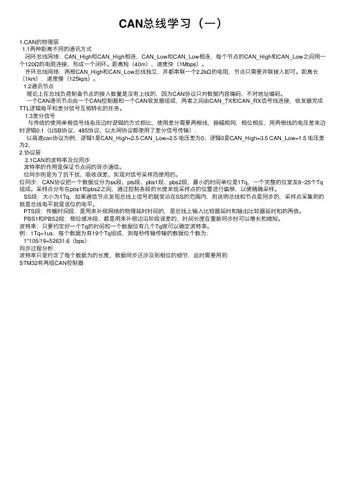
CAN总线学习(⼀)1.CAN的物理层1.1两种距离不同的通讯⽅式闭环总线⽹络:CAN_High和CAN_High相连,CAN_Low和CAN_Low相连,每个节点的CAN_High和CAN_Low之间⽤⼀个120Ω的电阻连接,形成⼀个闭环。
距离短(40m),速度快(1Mbps)。
开环总线⽹络:两根CAN_High和CAN_Low总线独⽴,并都串联⼀个2.2kΩ的电阻,节点只需要并联接⼊即可。
距离长(1km),速度慢(125kps)。
1.2通讯节点理论上在总线负荷制备节点的接⼊数量是没有上线的,因为CAN协议只对数据内容编码,不对地址编码。
⼀个CAN通讯节点由⼀个CAN控制器和⼀个CAN收发器组成,两者之间由CAN_TX和CAN_RX信号线连接,收发器完成TTL逻辑电平和差分信号互相转化的任务。
1.3差分信号与传统的使⽤单根信号线电压边时逻辑的⽅式相⽐,使⽤差分需要两根线,振幅相同,相位相反,⽤两根线的电压差来边时逻辑0.1(USB协议、485协议、以太⽹协议都使⽤了差分信号传输).以⾼速can协议为例,逻辑1是CAN_High=2.5 CAN_Low=2.5 电压差为0;逻辑0是CAN_High=3.5 CAN_Low=1.5 电压差为2.2.协议层2.1CAN的波特率及位同步波特率的作⽤是保证节点间的异步通信。
位同步则是为了抗⼲扰、吸收误差、实现对信号采样⽽使⽤的。
位同步:CAN协议把⼀个数据位分为ss段、pts段、pbs1段、pbs2段,最⼩的时间单位是1Tq,⼀个完整的位室友8~25个Tq 组成。
采样点分布在pbs1和pbs2之间,通过控制各段的长度来低采样点的位置进⾏偏移,以便精确采样。
SS段:⼤⼩为1Tq,如果通信节点发现总线上信号的跳变沿在SS的范围内,则说明总线和节点是同步的,采样点采集到的就是总线电平就是该位的电平。
PTS段:传播时间段,是⽤来补偿⽹络的物理延时时间的,是总线上输⼊⽐较器延时和输出⽐较器延时和的两倍。
CAN的工作原理及初始化CAN,全称为“Controller Area Network”,即控制器局域网CAN是一种多主方式的串行通讯总线,基本设计规范要求有高的位速率,高抗电磁干扰性,而且能够检测出产生的任何错误。
当信号传输距离达到10Km时,CAN 仍可提供高达50Kbit/s的数据传输速率。
由于CAN总线具有很高的实时性能,因此,CAN已经在汽车工业、航空工业、工业控制、安全防护等领域中得到了广泛应用。
CAN的结构:数据链路层:包括逻辑链路控制子层(Logical Link Control,LLC )和媒体访问控制子层(Medium Access Control,MAC)。
物理层:包括物理信号子层 (Physical Layer Signal,PLS) 、物理介质连接 (Physical Medium Attachment,PMA)和介质相关接口(Medium Dependent Interface,MDI) 。
1.物理层物理层定义信号是如何进行传输的,各部分的功能如下:(1)物理层信号PLS:实现位定时、位编码/解码、同步等功能。
理想发送器在没有重同步的情况下,每秒发送的位数定义为标称位速率,定义其倒数为标称位时间,它可分为同步段、传播段、相位缓冲段1和相位缓冲段2等几个互补重叠的时间段。
CAN位流根据“不归零”NRZ方式来编码,即在整个位时间里,位电平要么为显性,要么为隐性。
在隐性状态下,VCANH和VCANL被固定于平均电压电平,Vdiff近似为零。
显性状态以大于最小阈值的差分电压表示。
在显位期间,显性状态改变隐性状态并发送。
同步包括硬同步和重同步两种形式。
在一个时间内只允许一种同步。
仅当采样点之前检测到的数值与紧跟边沿之后出现的数值不同时,边沿才用于同步。
(2)物理介质连接PMA:实现总线发送/接收的功能电路,并可提供总线故障检测方法。
CAN2.0规范没有定义该层的驱动器/接收器特性,以便在具体应用中进行优化设计。
can物理层测试方法
物理层测试方法是指对计算机网络中的物理层进行测试和评估
的方法,目的是确保网络系统的正常运行和稳定性。
在网络系统中,物理层是连接计算机和网络设备的基础层,它负责将数字信号转换为物理信号,使计算机能够与其他设备进行通信。
物理层测试方法包括以下几个方面:
1. 电缆测试:电缆是连接计算机和网络设备的重要组成部分,通过对电缆进行测试,可以检测电缆是否有损坏、是否连接正确、是否存在干扰等问题。
2. 接口测试:计算机和网络设备之间的接口是通信的桥梁,通过对接口进行测试,可以检测接口是否兼容、是否能够正常传输数据等问题。
3. 信号测试:在网络系统中,数字信号和物理信号是相互转换的,通过对信号进行测试,可以检测信号是否稳定、是否存在噪声等问题。
4. 速率测试:计算机和网络设备之间的数据传输速度是影响通信效率的重要因素,通过对速率进行测试,可以检测数据传输速度是否达到了预期的要求。
5. 网络性能测试:网络性能是指网络系统在不同条件下的运行效率和稳定性,通过对网络性能进行测试,可以检测网络系统的带宽、延迟、丢包率等问题。
总之,物理层测试方法对于保证网络系统的正常运行和稳定性非常重要,它可以及时发现和解决网络系统中的各种问题,为网络系统的优化和提升提供有效的支持。
C A N总线(一)物理层—屏蔽双绞线-CAL-FENGHAI-(2020YEAR-YICAI)_JINGBIAN1、物理层一般要求1.1 物理层物理层实现网络中电控单元(ECU)的电连接。
ECU 的数目限制于总线线路的负载承受能力。
根据本部分的电气参数定义,在特定网段上ECU 的最大数目定为30。
1.2 物理介质物理介质为屏蔽双绞线。
双绞线特性阻抗为120Ω,电流对称驱动。
两条线分别命名为CAN_H 和CAN_L。
相应ECU 的管脚引线也分别用CAN_H 和CAN_L 来表示。
第三条连接屏蔽终端的线用CAN_SHLD 表示。
1.3 差动电压CAN_H和CAN_L相对于每个单独ECU地的电压有VCAN_H和VCAN_L 。
VCAN_H和VCAN_L间的差动电压由下式计算:Vdiff = VCAN_H — VCAN_L1.4 总线电平总线总是处于两种逻辑状态,即隐性和显性的其中之一(见图1)。
在隐性状态VCAN_H和VCAN_L 固定在一个中值电压电平。
在带终端电阻的总线上,Vdiff 接近于零。
显性状态由大于最小门限的差动电压表示。
显性状态覆盖隐性状态并在显性位中传输。
1.5 仲裁期间的总线电平在特定的位时间里,总线线路上两个不同的ECU 的显性位和隐性位的冲突仲裁结果是显性位。
(见图1)1.6 共模的总线电压范围共模的总线电压范围定义为CAN_H 和CAN_L 的边界电压值。
在连接在总线上的所有ECU 正常运行的前提下,CAN_H 和CAN_L 的电压值由各个ECU 对地测得。
1.7 总线终端在线路的两个末端上,必须接有负载电阻R 终结L。
RL 不得放置在ECU 中,以避免其中一个ECU 断线,总线将失去终端(见图2)。
1.8 内部电阻ECU 的内部电阻Rin 为隐性位状态,ECU 和总线线路断开下的CAN_H(或CAN_L)和ECU 地之间的电阻值。
(见图3)。
1.9 差动内部电阻ECU 的差动内部电阻Rdiff 为隐性位状态,ECU 和总线线路断开下的CAN_H 和CAN_L间的电阻值。
can物理层原理宝子!今天咱来唠唠物理层原理这个超有趣的东西。
你看啊,物理层就像是通信世界里的“快递员”,负责把数据从一个地方送到另一个地方。
想象一下,你要给远方的朋友寄个超级酷的小玩意儿,这个小玩意儿就是数据,那物理层就是那个把东西打包好,然后通过各种途径送出去的家伙。
物理层主要关心的是怎么在传输介质上传输比特流呢。
这比特流啊,就像是一串神秘的小珠子,0和1组成了各种奇妙的组合。
比如说,你在电脑上敲下一个字母“a”,在电脑内部它就被转化成了一串0和1的组合,然后物理层就接手这个任务啦。
传输介质那可真是多种多样。
就像咱们生活中的道路一样,有不同的类型。
最常见的就是电缆啦,电缆就像是一条专门为数据打造的“地下通道”。
里面的铜丝就像是轨道,比特流就沿着这些轨道欢快地跑着。
还有光纤呢,光纤就超级酷啦,它就像一条光的高速公路。
数据在光纤里是以光的形式传播的,速度那叫一个快,就像光剑一样瞬间就能到达目的地。
那物理层是怎么把数据准确地发送出去的呢?这里面就有好多好玩的东西啦。
比如说调制,这就像是给数据穿上不同的衣服。
如果是低频的信号,可能就像给它穿上了一件宽松的休闲装,方便在一些简单的传输介质里走。
如果是高频的信号呢,就像是穿上了一身紧身的运动装,适合在那些要求速度快的地方跑。
信号的传输还会遇到很多干扰呢。
就像你在路上走,可能会遇到刮风下雨,或者有调皮的小动物来捣乱。
在物理层里,噪声就是这个捣乱的家伙。
噪声可能来自各种各样的地方,比如周围的电器设备啊,或者是传输介质本身的一些小瑕疵。
物理层就得想办法克服这些噪声,就像你要保护好自己的小包裹,不让它被风吹走或者被小动物弄破。
物理层还有一个重要的任务就是确定传输速率。
这就像是快递员要决定自己走路或者骑车的速度一样。
如果传输速率太快,可能就像你骑车骑得太快,容易摔倒,数据就容易出错。
如果太慢呢,又像你走路慢悠悠的,效率太低啦。
所以要找到一个合适的传输速率,让数据既能准确到达,又不会花费太多的时间。