ARKAL过滤器用户手册
- 格式:pdf
- 大小:559.29 KB
- 文档页数:17


ISLS311SX1 Rev BHayward Flow ControlOne Hayward Industrial DriveLS Series AQUATIC SAND FILTEROwner’s ManualMODELS: LS311SX & LS360SX IMPORTANT SAFETY INSTRUCTIONSSAVE THIS INSTRUCTION MANUALBasic safety precautions should always be followed, including the following: Failure to follow instructions cancause severe injury and/or death.This is the safety-alert symbol. When you see this symbol on your equipment or in this manual, look for one ofthe following signal words and be alert to the potential for personal injury.WARNING warns about hazards that could cause serious personal injury, death or major property damage and if ignored presents a potential hazard. CAUTION warns about hazards that will or can cause minor or moderate personal injury and/or property damage and if ignored presents a potential hazard. It can also make consumers aware of actions that are unpredictable and unsafe. The NOTICE label indicates special instructions that are important but not related to hazards.Table of Contents1. IMPORTANT SAFETY INSTRUCTIONS ................................................................................................................................. 22.Introduction ...................................................................................................................................................................... 4 3. How It Works .................................................................................................................................................................... 4 4. Installation ........................................................................................................................................................................ 4 5. Initial Start-Up of Filter ..................................................................................................................................................... 5 6. Filter Control Valve Functions ........................................................................................................................................... 6 7. Specifications .................................................................................................................................................................... 6 8. Replacement Parts (7)1. IMPORTANT SAFETY INSTRUCTIONSWARNING - Read and follow all instructions in this owner’s manual and on the equipment. Failure to follow instructions can cause severe injury and/or death .CAUTION – This FILTER is not intended to be used in swimming pools or spas. It is specifically designed to be used where bathers are NOT subjected to suction outlets while the pump is in operation.WARNING – Hazardous Pressure. Water circulation systems operate under hazardous pressure during start up, normaloperation, and after pump shut off. Stand clear of circulation system equipment during pump start up. Failure to follow safety and operation instructions could result in violent separation of the pump housing and cover, and/or filter housing and clamp due to pressure in the system, which could cause property damage, severe personal injury, or death. Before water circulation system, all system and pump controls must be in off position and filter manual air relief valve must be in open position. Beforestarting system pump, all system valves must be set in a position to allow system water to return back to the system. Do not change filter control valve position while system pump is running. Before starting system pump, fully open filter manual air relief valve. Do not close filter manual air relief valve until a steady stream of water (not air or air and water) is discharged.WARNING–Separation Hazard.Failure to follow safety and operation instructions could result in violent separation of pump and/or filter components. Strainer cover must be properly secured to pump housing with strainer cover lock ring. Before servicing circulation system, filters manual air relief valve must be in open position. Do not operate circulation system if a system component is not assembled properly, damaged, or missing. Do not operate circulation system unless filter manual air relief is in fully screwed into filter cap. Never operate or test the circulation system at more than 50 PSI. Do not purge the system with compressed air. Purging the system with compressed air can cause components to explode, with risk of severe injury or death to anyone nearby. Use only a low pressure (below 5 PSI), high volume blower when air purging the pump, filter, or piping.WARNING–Risk of Electric Shock. All electrical wiring MUST be in conformance with applicable local codes, regulations, and the National Electric Code (NEC). Hazardous voltage can shock, burn, and cause death or serious property damage. To reduce the risk of electric shock, do NOT use an extension cord to connect unit to electric supply. Provide a properly located electrical receptacle. Before working on any electrical equipment, turn off power supply to the equipment. To reduce the risk of electric shock replace damaged wiring immediately. Locate conduit to prevent abuse from lawn mowers, hedge trimmers and other equipment. Do NOT ground to a gas supply line.WARNING–Risk of Electric Shock.Failure to ground all electrical equipment can cause serious or fatal electrical shock hazard. Electrical ground all electrical equipment before connecting to electrical power supply.WARNING –Risk of Electric Shock. Failure to bond all electrical equipment to system structure will increase risk for electrocution and could result in injury or death. To reduce the risk of electric shock, see installation instructions and consult a professional electrician on how to bond all electrical equipment. Also, contact a licensed electrician for information on local electrical codes for bonding requirements.WARNING –Risk of Electric Shock . The electrical equipment must be connected only to a supply circuit that is protected by a ground-fault circuit-interrupter (GFCI). Such a GFCI should be provided by the installer and should be tested on a routine basis. To test the GFCI, push the test button. The GFCI should interrupt power. Push reset button. Power should be restored. If the GFCI fails to operate in this manner, the GFCI is defective. If the GFCI interrupts power to the electrical equipment without the test button being pushed, a ground current is flowing, indicating the possibility of an electrical shock. Do not use this electrical equipment. Disconnect the electrical equipment and have the problem corrected by a qualified service representative before using.2. IntroductionYour Hayward LS Series high-rate sand filter is a high performance, corrosion-proof filter that blends superior flow characteristics and features with ease of operation. It represents the very latest in high-rate sand filter technology. It is virtually foolproof in design and operation and when installed, operated and maintained according to instructions, your filter will produce clear, water with only the least attention and care.3. How It WorksYour filter uses special filter sand to remove dirt particles from the water. Filter sand is loaded into the filter tank and functions as the permanent dirt removing media. The system water, which contains suspended dirt particles, is pumped through your piping system and is automatically directed by the patented filter control valve to the top of the filter tank. As the system water is pumped through the filter sand, dirt particles are trapped by the sand bed, and filtered out. The cleaned system water is returned from the bottom of the filter tank, through the control valve and back to the system through the piping system. This entire sequence is continuous and automatic and provides for total recirculation of system water through your filter and piping system.After a period of time, the accumulated dirt in the filter causes a resistance to flow, and the flow diminishes. This means it is time to clean (backwash) your filter. With the control valve in the backwash position, the water flow is automatically reversed through the filter so that it is directed to the bottom of the tank, up through the sand, flushing the previously trapped dirt and debris out the waste line. Once the filter is backwashed (cleaned) of dirt, the control valve is manually sequenced to Rinse, and then Filter, to resume normal filtering.4. InstallationOnly simple tools (screwdriver and wrenches), plus PTFE tapemanufactured for plastic adapters, are required to install and/or service the filter.1. The filter system should be installed, not more than 6 feet above system water level, on a level concrete slab,very firm ground, or equivalent, as recommended by your dealer. Position the filter so that the piping connections, control valve, and drain are convenient and accessible for operation, and service.2. Assemble the filter control valve to filter. Align the two (2) valve pipe connections, with O-rings in place, withthe two openings in the side of the filter tank and press in firmly. Secure the assembly to the tank connections with the two bulkhead locknuts. Do not overtighten.3. Loading sand media. Filter sand media is loaded through the top opening of the filter.a. Remove the top diffuser from the internal diffuser elbow pipe and place flexible, automatic air relief tube tothe side, out of the way, inside the tank.b. Cap the internal diffuser elbow pipe with the sand shield provided to prevent sand from entering it.c. It is good practice to fill tank approximately 1/2 way with water to provide a cushioning effect when thefilter sand is poured in. This helps protect the under-drain laterals from excessive shock. (Be sure the drain cap is securely in place on drain pipe.)Note: Confirm all laterals are in the down position before loading with sand. (See Diag A on Page 7.)d. Carefully pour in correct amount and grade of filter sand, as specified. Sand surface should be leveled andshould come to about 6” from the top of the filter tank. Use no more than the recommended amount of sand.e. Remove the sand shield from internal diffuser elbow pipe.f. Replace diffuser on internal diffuser elbow pipe, positioning automatic air relief tube through theholeprovided in the diffuser.g.Wipe filter flange clean.h.Insert top closure dome (with flange O-ring in place) into the tank neck. Place clamp around dome flangeand tank flange and tighten with screwdriver, tapping around clamp with screwdriver handle to help seatflange clamp.Do not overtighten.4.Connect pump to control valve opening marked PUMP according to instructions. Make return to system pipeconnection to control valve opening marked RETURN and complete other necessary plumbing connections, suction lines to pump, waste, etc.5.Make electrical connections to pump per pump instructions.6.To prevent water leakage, be sure drain cap is securely in place and all pipe connections are tight.5.Initial Start-Up of Filter1.Be sure correct amount of filter sand media is in tank and that all connections have been made and are secure.IMPORTANT: To prevent unnecessary strain on piping system and valving, always shut off pump beforeswitching Filter Control Valve positions.2.Depress LS control valve handle and rotate to BACKWASH* position. (To prevent damage to control valve seat,always depress handle before turning.)3.Prime and start pump according to pump instructions. (be sure all suction and return lines are open), allowingthe filter tank to fill with water.WARNING–SEPARATION HAZARD: All suction and discharge valves must be open when starting the system. Failure to do so could cause severe personal injury and/or property damage.4.Once water flow is steady out the waste line, run the pump for at least 2 minutes. This initial backwashing of thefilter is recommended to remove any impurities or fine sand particles in the sand media.5.Turn pump off and set LS valve to RINSE position. Start pump and operate until water insight glass is clear—about 1/2 to 1 minute. Turn pump off, set valve to FILTER position and restartpump. Your filter is now operating in the normal filter mode, filtering particles from the systemwater.6.Adjust system suction and return valves to achieve desired flow. Check system and filterfor water leaks and tighten connections, bolts, nuts, as required.7.Note the initial pressure gauge reading when the filter is clean. (It will vary from system tosystem depending upon the pump and general piping system.) As the filter removes dirt and impurities from the system water, the accumulation in the filter will cause the pressure to rise and flow todiminish. When the pressure gauge reading is 6-8 PSI (0.41-0.55 BAR) higher than the initial "clean" pressure you noted, it is time to backwash (clean) the filter (see BACKWASH under Filter Control Valve Functions).NOTE: During initial clean-up of the system water it may be necessary to backwashfrequently due to the unusually heavy initial dirt load in the water.To prevent damage to the pump and filter and for proper operation of the system, clean pump strainerregularly.6.Filter Control Valve FunctionsFILTER — Set valve to FILTER for normal filtering. Also use for regular vacuuming.BACKWASH — For cleaning filter. When filter pressure gauge rises 8-10PSI (0.55-0.69 BAR) above start-up(clean pressure): Stop the pump, set valve to BACKWASH. Start pump and backwash until water in sightglass is clear. Proceed to RINSE.RINSE — After backwashing, with pump off, set valve to RINSE. Start pump and operate for about 1/2 to 1minute. This ensures that all dirty water from backwashing is rinsed out to the filter to waste, preventingpossible return to the system. Stop pump, set valve to FILTER, and start pump for normal filtering.WASTE — To bypass filter for draining or lowering water level and for vacuuming heavy debris directly towaste.RECIRCULATE — Water is recirculated through the system, bypassing the filter.CLOSED — Shuts off flow from pump to filter.VACUUMING— Vacuuming can be performed directly into the filter. When vacuuming heavy debris loads,set valve to WASTE position to bypass the filter and vacuum directly out to waste.WINTERIZINGpletely drain tank by unscrewing drain cap at base of filter tank. Leave cap off during winter.2.Depress the LS control valve handle and rotate so as to set pointer on valve top between any two positions. Thiswill allow water to drain from the valve. Leave valve in this "inactive" position.3.Drain and winterize pump according to pump instructions.7.SpecificationsTable 1 **Also known as No. 20 Silica Sand8. Replacement PartsREPLACEMENT PARTS LISTINGISLS311SX1 Rev B。
These instructions must be thoroughly read and understood before installing and operating this product. All installation, operation, and maintenance activities should be performed by suitable personnel using reasonable care. If you have any questions or concerns, please call the Technical Services Department at 800-343-4048, 8AM to 5PM Eastern Time or email at*****************************(NorthAmerica).Forotherlocations,pleasecontactyourlocal representative.Please save product packaging for future use.The filter-regulator should be installed on the compressed gas line as close as possible to the point of use. If there is sufficient liquid entrained in the gas to coalesce and drain from the filter cartridge, the filter-regulator must be installed vertically, with the drain port down. If liquid drainage is not expected, the filter-regulator may be mounted horizontally (except for those models equipped with an automatic float drain). If the compressed air supply contains excessive amounts of water and compressor oils, a drip leg and a properly sized prefilter should be installedupstream from the filter regulator. (Request the FNS Catalog or call your local Representative for more information.)Use only non-detergent mineral base oils with assemblies containing polycarbonate e of any other types of oils could lead to dangerous failure of the product.Pipe the gas to be regulated to the inlet port (marked “IN”, or as indicated by a flow arrow). The remaining three ports will be at the regulated pressure. Use the port opposite the inlet as the outlet, use one of the remaining two ports as the gage port, and plug the unused port.Set the desired outlet pressure by adjusting the knob or T-handle at the top of the regulator. Set the pressure under flow conditions, rather than no-flow conditions. If the regulator setting is fixed for no-flow conditions, the control pressure will decrease rather sharply when flow starts and then hold relatively constant close to the maximum flow capacity of the regulator.If the pressure control setting is reduced, the excess pressure downstream from the regulator will be relieved through the regulator and vented to the atmosphere. The regulator is protected by the filter and does not require routine maintenance (other than filter cartridge replacement). To avoid damaging the regulator, do not use the regulator when the filter cartridge is not installed in the filter housing. In the event of damage to the regulator, a complete regulator repair kit may be purchased (see Replacement Parts list).Turn off compressed air flow to the filter regulator and depressurize the filter housing prior to performing maintenance activities on the product.The only preventive maintenance required for the Balston filter-regulator is changing the filter cartridge on an annual basis (or more often, as dictated by the cleanliness of the gas supply).A Balston Microfibre ® Filter Cartridge continues to filter at its original efficiency even when it is wet with liquids. The life of the filter cartridge is determined by the increase in flow resistance resulting from trapped solids in the filter cartridge. The filter cartridge should be changed every 12 months. Part numbers for replacement cartridges are shown in the table on the reverse side of this data sheet.Changing filter cartridges more frequently will translate into direct energy savings and reduced operating costs.Annual electricity costs to operate a typical 100 HP compressor can be as high as $50,000. Pressure drop in the system adds to this expense. A system operating at 100 psig that is experiencing a 2 psig pressure drop through a filter, requires an additional 1% in operating energy costs or approximately $500.00+ per year.Failure of the filter cartridge resulting from a high pressure drop or excessive solids loading may cause damage to the filter housing and/or any downstream equipment.Balston Microfibre Filter Cartridges are sealed into place by compression against a flat surface. No gaskets are required between the filter cartridge and the filter housing. The filter cartridge is securely sealed by tightening the element retainer by hand. It is not necessary to use excessive force in tightening the element retainer, and no tools should be used.!InstallationOperationMaintenance!Balston Filter-Regulator Model AFR-940Installation, Operation, and Maintenance Manual®Bulletin TI-131RParker Hannifin CorporationFiltration and Separation Division Haverhill, MA • 1-800-343-4048/balstonFilter-Regulator Replacement Cartridges AFR-940, 940A050-05-BXERegulator Repair Kit93532ReplacementFilter CartridgesControl Range0-30 psig (0-2.1 barg)5-60 psig (0.5-4.1 barg)10-130 psig (1.0-9.0 barg) AFR-940AFR-940-30AFR-940-60AFR-940-130AFR-940A AFR-940A-30AFR-940A-60AFR-940A-130OptionalAccessoriesDescription Part NumberAuxiliary Prefilter2002N-1B1-DXMaterials of ConstructionPort Gauge Max.Max.ShippingSize Ports Head Bowl Bonnet Internals Temp.Press. (1)WeightAFR-9401/4" NPT1/8" NPT Anod. Alum.Polycarb.Polycarb.Brass/Buna220°F (104°C)150 psig (10.3 barg)0.5 lbs (0.2 kg) AFR-940A1/4" NPT1/8" NPT Anod. Alum.Anod. Alum.Polycarb.Brass/Buna220°F (104°C)250 psig (17.2 barg)0.5 lbs (0.2 kg)Parker Filtration & SeparationFiltration Group EuropeHermitage Court, Hermitage LaneMaidstone, Kent ME16 9NT, EnglandTel: +44 (01622) 723300 Fax: +44 (01622) 728703/pagCopyright© Parker Hannifin Corporation 1987, 2008Printed in U.S.A. Bulletin TI-131R Parker Hannifin CorporationFiltration and Separation Division242 Neck Road, P.O. Box 8223Haverhill, MA 01835-0723Tel: 978-858-0505 Fax: 978-556-7501/balstonNotes:1 Maximum pressure ratings are fortemperatures to 130°F (54°C). Pleaseconsult the factory for maximum pressureratings at elevated temperatures.Bulletin TI-131R Installation, Operation and Maintenance Manual Technical Information Balston Filter-Regulator Model AFR-940When reading the control characteristics chart, first determinethe initial outlet pressure that will be used at zero flow. Find theappropriate pressure curve. Follow the curve until it intersectsthe desired flow. This point is the outlet pressure at thedesired flow rate.。
本实用新型公开了一种精密过滤机, 包括一主体桶, 主体桶上部开设有出水口, 下部开设有进水口, 所述进水口下方设置有固定圆板, 所述进水口上方设置有滤芯固定凹槽, 所述固定圆板与所述滤芯固定凹槽之间连接有多组滤芯, 所述的滤芯与固定圆板之间设置有密封圈, 滤芯顶部开设有滤芯出水口。
本实用新型的过滤量能够增加2倍以上, 最大可达55T/H。
滤材清洗更换方便, 劳动强度降低60%-70%。
过滤过程中彻底杜绝漏活性炭、过滤不干净及漏水问题, 不需人工排气, 省时省力。
1、一种精密过滤机, 其特征在于: 包括一主体桶( 10) , 主体桶( 10) 上部开设有出水口( 3) , 下部开设有进水口( 6) , 所述出水口( 3) 下方设置有固定圆板( 12) , 所述进水口( 6) 上方设置有滤芯固定凹槽( 15) , 所述固定圆板( 12) 与所述滤芯固定凹槽( 15) 之间连接有多组滤芯( 4) , 所述的滤芯( 4) 与固定圆板( 12) 之间设置有密封圈( 13) , 滤芯( 4) 顶部开设有滤芯出水口( 14) 。
2、根据权利要求1所述的精密过滤机, 其特征在于: 所述固定圆板( 12) 上设置有压板( 11) 。
3、根据权利要求1所述的精密过滤机, 其特征在于: 所述主体桶( 10) 顶部连接有上盖( 9) , 上盖( 9) 上设置有上束环组( 1) 。
4、根据权利要求1所述的精密过滤机, 其特征在于: 所述主体桶( 10) 固定在机架附底板( 16) 上方, 所述进水口( 6) 下方依次连通有泵浦( 8) 、进水阀( 7) 和注水桶( 5) 。
5、根据权利要求1所述的精密过滤机, 其特征在于: 所述主体桶( 10) 侧面连接有压力表组( 2) 。
精密过滤机技术领域本实用新型涉及一种电镀、化学药液过滤机, 用于实验室化学试剂过滤、除杂等, 特别涉及一种精密过滤机。
背景技术现有的精密过滤机存在以下问题:1、在使用过程中因密封结构问题, 导致过滤不干净及漏水。
微孔过滤器ZG-10.0使用说明书制作单位:生产基地:公司电话:公司传真:邮 编:编制日期:目录一、 产品介绍 (3)二、产品特点 (3)三、滤芯的选择 (3)四、设备技术参数 (4)五、使用说明 (4)六、操作注意事项 (6)七、设备的维护与保养 (6)八、售后服务承诺 (7)九、合格证 (7)十、随机附件表 (8)一、产品介绍:本设备可用于食品、乳品、饮料、酒类、中药、化工行业的液体物料的气体的过滤。
采用折叠式滤芯,折叠式滤芯是一种先进的固定型深层过滤芯,过滤公称精度范围可以从0.1μm直600.1μm。
滤膜不受进料压力波动而影响过滤精度。
其特有的低压差,高通量、良好的过滤精度能较低的经济费用成为取代线绕式、棉饼和纸板等非固定型过滤芯的新型滤芯而深受用户欢迎。
二、产品特点:①化学相容性广、流通量大、压差低、使用寿命长。
②过滤精度范围广、选择度大、可满足各种应用场合。
③采用热熔工艺,牢固且无释放物污染产品。
三、滤芯的选择:1、滤芯的用途很广泛,滤芯的品种、规格较多,选择型号是很重要的。
根据用途可分为过滤液体和气体二种,规格大小可以分为5〃、10〃、20〃、30〃和40〃等。
工作压力一般在0.1Mpa—0.4 Mpa。
由于滤芯孔径不同,其流量也不尽相同,如0.2um—0.4 um过滤沌水的标准在300—500kg/h,如果要提高每小时的过滤量,则可以用多芯或20〃、30〃、40〃英寸组合,例如要过滤5t/h的无菌水,则可以选用0.2 um,30英寸7芯的过滤器。
若过滤杂质多且有粘度,则应添加前置预过滤设备。
气体的过滤与液体过滤稍有不同,它的过滤量以每分钟立方气体来计算。
10英寸滤芯,孔径φ0.22 um,压力在0.12 Mpa,压差在0.01 Mpa时,流量为4-6m3/min,在发酵工业上广泛应用。
2 、合适的滤芯,选用适当的孔径,若要除菌则选用0.2um-0.5um孔径的滤芯、药用针剂、抗菌素、血制品等用聚砜滤芯。
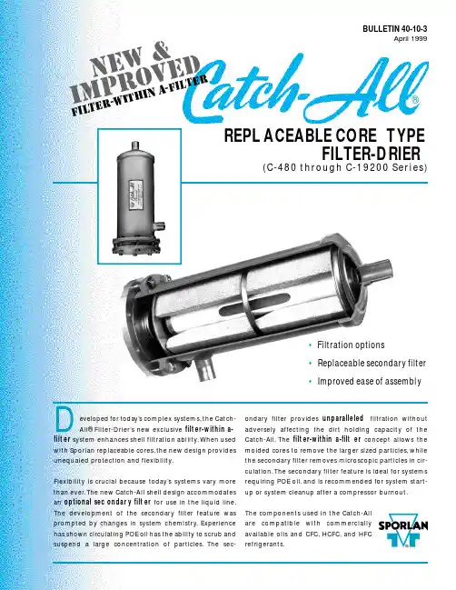
eveloped for today’s co m p l e x sys t e m s ,the Catc h -All® Fi l t e r -D ri e r ’s new exc l u s i v e f i l t er-within a-f i l t er s y s t em enhances shell filtration ability.When used with Spo r lan re p l a c eable co r e s ,the new design prov i d e s unequaled pro t e c tion and flex i b i l i t y.Fl e x i b i l i t y is crucial be c ause tod a y’s sys t ems va r y more than eve r .The new Catc h -A ll shell design acco m m o d a te s an optional sec o n d a r y filt e r for use in the liquid line.The deve l o p m e n t of the seco n d a r y filter fe a t u r e wa s p r o m p t ed by changes in sys t em chemistry.E x p e r i e n c e has shown circ u l a ting POE oil has the ability to scrub and s u s p end a large co n c e n t r ation of part i c l e s .The sec-o n d a r y filter provides u n p a r a l l e l e d f i l t r ation without a d versely affe c ting the dirt holding ca p a c i t y of the Catc h -A l l .The f i l t er-within a-filt e r co n c ept allows the molded co r es to re m o ve the larger sized part i c l e s ,w h i l e the seco n d a r y filter re m o ves micro s c opic particles in cir-c u l a t i o n .The seco n d a r y filter fe a t u r e is ideal for sys t e m s re q u i r ing POE oil,and is re c ommended for sys t em start-up or sys t em cleanup after a co m p r e s s o r b u r n o u t .The co m p o n e n ts used in the Catc h -A l l a r e co m p a tible with co m m e r c i a l l y available oils and CFC,H C F C ,and HFC re f r i g e r a n t s .BULLETIN 40-10-3April 1999REPL ACEABLE CORE TYPEFILTER-DRIER(C-480 through C-19200 Se r i e s)Integral to the redesign are these…DESIGN FEATURES•The Catch-All shell utilizes an exclusive filter-within a-filter construction . The new internal assembly,when used with Sporlan molded cores, provides maximum water capacity, excellent acid removal charac-teristics, the ability to remove products of oil decomposition, and outstanding filtration. The optional replaceable secondary filter offers unsurpassed filtration efficiencies without compromising the Catch-AllÕs ability to hold a large amount of foreign material. The assembly is designed so the cores remove larger sized particles while the secondary filter removes microscopic particles. This unique construction aggressively filters particles circulating in a refrigerant system.•The shell redesign offers flexibility . The new internal assembly can be used with or without the secondary filter. The type of fil-tration needed depends upon the system requirements or appli-cation. Using the assembly without the secondary filter offers the same time tested, field-proven, filtration characteristics expected in a Catch-All Filter-Drier.•The internal construction is designed to improve ease of assem-bly . The molded cores simply slide over the center tube, fol-lowed by spacer plates (if applicable). The outlet plate is fastened to the assembly by a wing screw. With the addition of a spring, the resulting assembly is easy to install and remove.•The seal gasket prevents solid contaminants from bypassing the filter. The assembly is held tight against the gasket by a spring.O-rings are used with the secondary filter to provide a tight seal.•The internal parts are plated steel Ð no plastic parts.•The bolt and nut attachment of the end plate allows for simple,trouble-free installation. The nuts lock against the side of the shell for ease in tightening. Other designs, using cap screws threaded into the flange ring, run the risk of twisting off the head of the screw making removal difficult.•Copper fittings are excellent for fast easy soldering. Fittings are pre-sized for proper fit, and suitable for use with soft solder, sil-ver solder, Sil-Fos, or Phos-Copper. The fittings are brazed to the shell with a high temperature brazing alloy so they never come loose during the brazing operation on the job.•A complete line of fitting sizes are available with solder con-nections from 1/2Ó to 2-1/8Ó ODF.•Heavy steel shells provide high bursting strength and are listed by UnderwritersÕLaboratories Inc. and Canadian Standards Association.•The shell exterior uses an epoxy powder coating to prevent corrosion even under the most adverse condi-tions.Page 2/ BULLETIN 40-10-3The construction illustrated is used on the C-480 through C-19200 Series Catch-All Filter-Driers (ODF Solder models only)manu f actured a f ter 6/99.The C-R420,C-30,000,and C-40,000 Series models differ in construction,but maintain the f ield-proven features which have been used suc-cessfully for many years.C-967Exploded ViewFEATURES®BULLETIN 40-10-3 / Page 3APPLICATIONThe C-480 through C-19200 Series Replaceable Core Type Catch-All Filter-Driers are designed to be used in the liquid line. Place the Catch-All immediately ahead of other liquid line controls, such as the ther-mostatic expansion valve, solenoid valve, and See¥All¨Moisture and Liquid Indicator. When applied in this way, the filter-drier provides maximum protection for the thermostatic expansion valve and solenoid valve from dirt that may be in the system. If the system contains appreciable amounts of moisture, this location gives the best results in protecting the thermostatic expansion valve from freeze-up. If possi-ble, place the filter-drier in a cold location on the liq-uid line. Acid capacity is not affected by differences in liquid line temperature.The secondary filter feature is ideal for systems with POE oil, and is recommended for system start-up or system cleanup after a compressor burnout.Because of flow considerations, the new C-480 through C-19200 Series Replaceable Core Type Catch-All Filter-Driers are not recommended for the suction line. Sporlan manufactures Replaceable Suction Filter(RSF) shells specifically for suction line installations. The RSF shell is designed to allow maximum vapor flow with a minimum pressure drop whether the installer is using filter elements or mold-ed cores.Catch-All Filter-Driers are not recommended in the discharge line. There are better locations. The water capacity in this location is greatly reduced due to the high operating temperature.Catch-All Filter-Driers may be installed in any position, with top or bottom feed. However, it is advisable to mount replaceable core models horizontally so that for-eign material cannot drop into the outlet fitting when the cores are removed. Always observe the flow direction. Catch-Alls must never be subjected to reverse flow.The Catch-All should be installed in the main liquid line for maximum protection. When located in a bypass line, dirt or foreign material may pass into the system through the unprotected line. When a bypass installation is necessary, consult Bulletin 40-10.The components used in the Catch-All are compatible with commercially available CFC, HCFC, and HFC refrigerants and oils. The new internal assemblies are not suitable for use on ammonia systems. All Replaceable Core Type Catch-All Filter-Driers with NPT female connections, supplied with the tie rod construction, are suitable for CFC, HCFC, and HFC refrigerants plus ammonia.SELECTIONThe C-480 through C-19200 Series Catch-All Filter-Driers should be selected in accordance with the Liquid Refrigerant Flow Capacities and Selection Recommendations in Bulletin 40-10. Catch-All shells incorporating the new construction, even with the sec-ondary filter, have liquid flow capacities equal to or slightly greater than the shells using the tie rod con-struction.Water and acid capacities of the Replaceable Core Type Catch-Alls have not changed. Consult Bulletin 40-10 on the water capacities of these models at ARI Standard Conditions. Acid removal is difficult to measure. There are no standard ratings to follow. However, both labo-ratory and field tests have demonstrated that the Catch-All core has far superior acid removal ability Ð many times that available in other driers.Filtration characteristics of a filter-drier are not readily defined or evaluated since laboratory tests cannot accu-rately reproduce the range of conditions and contami-nants seen in an actual system. The ability to filter and hold foreign matter varies with the brand and type of fil-ter-drier. The simplest guide to follow is that filter capacity is proportional to filtering area. Filters should be selected with an adequate reserve capacity to allow for the contamination found in most systems.APPLICATION / SELECTION ®Page 4/ BULLETIN 40-10-3* Two O-rings are required for each internal assembly and are sup-plied with each secondary filter.The O-rings,part no.621-025,can also be purchased separately.Previous Designs –Parts kits for the new internal construction fit in shell Designs B and C.Converting shell Design B does require a thicker outlet retainer ring plate gasket,part no.1288-014.The new internal construction cannot be used in Design A.Consult Bulletin 122 for replacement part specifications for Design A.R eplacement Parts and Kits are available through Sporlan Authorized Wholesalers.AssemblyOptional Secondary FilterShellFlange Bolts and NutsDesign DManufactured June 1999P RINTEDINU.S. OF A. ©C OPYRIGHT 1999 S PORLAN V ALVE C OMPANY , W ASHINGTON , M ISSOURI 15-499Design AManufactured until 1983Design B )Manufactured 1983-1991)Manufactured 1991 - Present(“Press Fit”onto Plate,Outlet Core Retainer)NutShellare included)Tie Rod(3 Req’d)Outlet Screen Gasket (Felt)Tie Rod(3 Req’d)Tie Rod(3 Req’d)Nut NutPlate Gasket)The B and C design can be differentiated by external shell appear-ance. The welded end cap on the outlet of the shell fits inside the body shell on the B version and it slides over the body shell on the C version.(“-P”Type Catch-Alls Only)Retainer Plate Gasket。


TABLE OF CONTENTS INTRODUCTION (2)INSTALLATION (3)Setup (3)Enclosure Assembly for Stand Alone Final Filters (6)Door Installation (6)Enclosure Anchoring (7)Ducting a Stand Alone Final Filter (7)Filter Cartridge Installation (8)Cartridge Support Installation (9)Compressed Air Supply (10)Electrical Connections (10)The Wiring Process (10)Choosing the Correct Wiring Procedure (11)Wiring from the Timer Board to the Solenoid (11)Photohelic Connections (11)Initial Checks (12)OPERATION (13)Electrical Settings (13)Solenoid Sequence Setup (13)Selector and Push Button Switch Operation (13)Startup (13)MAINTENANCE (15)Periodic Maintenance Schedule (15)Filter Cartridge Replacement (15)SPARE PARTS LISTING (17)INTRODUCTIONThe Osprey Final Filter is designed to enhance the filtering capacity of the Osprey Drum Filter or Phoenix TM Filter System. The purpose is to filter fine particulate material from an air stream. The filter cartridges remove 99.95% of particulate matter down to 1 micron. Clean air can be exhausted into manufacturing plant, atmosphere, or temperature control system.The Final Filter uses a long lasting, fiber resistant cartridge design. This allows easy installation, low maintenance, and automatic pulsejet cleaning.This manual was written for the Osprey Final Filter and is applicable to all sizes of the Osprey Final Filter. Drawings in this manual apply to the base model unless otherwise noted.This manual is divided into five sections:1) Introduction2) Installation and Start-up3) Operation4) Maintenance5) Spare Parts ListingSafety information and information of special note are included throughout the manual. Four different types of notes are used in this manual and appear as shown.is used to prevent personnel injury.-WARNING-is used to prevent personnel injury.is used to prevent machine damage.-CAUTION-is used to prevent machine damage.is used to show information that is necessary to insure proper installationmation that is necessary to insure proper installation -IMPORTANT-is used to show inforand operation.and operation.is used to provide information of special interest.-NOTE-is used to provide information of special interest.INSTALLATIONSetupFirst, check the crates shipped against the shipping list to identify missing or damaged parts. Follow the instructions in the bulletin titled “What to do if your shipment is damaged, lost, or stolen!” located in the Osprey job manual shipped with the equipment, if applicable. If all is well, uncrate the Final Filter and gather the parts near, but not on, the planned erection site. Before beginning installation, go over the assembly drawings (included in the Osprey job manual shipped with the equipment) to become familiar with the components that will require assembly. Also, read the Drum Filter (or Phoenix TM Filter) Installation and Operation Manual completely. Install the drum filter and begin installation of the enclosure before installing the Final Filter. Assembly of the Final Filter section is best done while installing the drum filter enclosure. Use Figure 1 and the assembly drawings specific to your equipment (included in the Osprey job manual) as a guide throughout this installation. If you have purchased a stand alone Final Filter, assemble the filter enclosure following the section labeled “Enclosure Assembly for Stand Alone Final Filters”.Assemble the drum enclosure except for the roof and front wall where the main system fan isFigure 1 Osprey Final Filter overall layout.Assemble the tubesheet panels intheir proper placein the samemanner as theenclosure wallpanels wereinstalled. Also,install the tubesheet-flashingpanel at this time.Be sure to placesilicone (includedin shipment)between allmating panelflanges.See Figures 2 and3 for examples.Figure 2 Assembled tube sheet panels and tube sheet flashing, as viewed through the drum plenum wall.Figure 3 Assembled tube sheet panels and tube sheet flashing from a stand alone Final Filter.Figure 4 Manifolds installed on manifold mounts.Bolt on the enclosure roof panels at this time. This will steady the tube sheet panels for the rest of the installation.Bolt the manifold mounts into their proper position, aligning the holes on its flange with the row of holes down the center of the tube sheet panels. Use 3/8"-16 wiz bolts and nuts to bolt it.Locate the manifold mount braces and bolt them to the tube sheet panels and to the manifold mounts using 3/8"-16 wiz bolts and nuts.Now, find the air manifolds. The air manifolds come preassembled with the diaphragm valves, solenoid valves, and air hoses. Secure them to the manifold mount braces installed earlier using 3/8"-16 x 1 1/4" bolts, 3/8" washers and lock washers, and 3/8"-16 nuts.When the manifolds are installed, install the manifold stiffeners. These keep movement and vibration of the manifolds to a minimum when the diaphragm valves are activated and the filter cartridges are pulse cleaned.-NOTE- Hardware may differ for someassemblies. Check the assemblydrawings shipped with theequipment for proper mountinghardware.hardware.-WARNING-Do not damage Do not damagethe air hoses the air hoseswhen installing when installingthe manifolds the manifoldsand manifold and manifoldstiffeners.stiffeners.Figure 4 shows an installation of the tubesheet panels, manifold mounts and brackets,the manifolds, and the manifold stiffeners.-NOTE-Act Actual assemblies may ual assemblies may ual assemblies maydiffer from figures differ from figuresused in this manual. used in this manual.Consult the assembly Consult the assemblydrawings shipped with drawings shipped withthe equipment for the equipment for details.details.Figure 5 Stand Alone Final Filter Enclosure (partiallyassembled).Enclosure Assembly for Stand Alone Final FiltersDetermine component/equipment arrangement and establish critical locations for major items and mark on floor in appropriate manner (chalk line). Consult customer and/or Osprey drawings for details (Footprint drawings are available from Osprey).-IMPORTANT- Some panels are not interchangeable. Compare the tags located on the top ofeach panel with the enclosure assembly drawing(s) included in the blue jobmanual shipped with the equipment.Assemble the front wall by first laying two panels on the ground and putting a bead of silicone (supplied by Osprey) on the end flanges of the two mating wall panels to ensure an airtight seal. Bolt the two flanges together using 3/8"-16 wiz nut and bolts supplied with the equipment. When the wall is assembled, raise it into place keeping it aligned with the mark that was make on the floor earlier. Anchor the wall to the foundation by drilling through every other hole in the bottom flanges of each panel and securing with an appropriate fastener (not supplied by Osprey). Figures 2 and 5 show a stand-alone Final Filter being assembled.together. In addition, the enclosure panels must level and plumb to insure proper fit, so shim necessary.-NOTE- Do not anchor these panels to foundation at this time. assembly is complete.wall panels are installed to ease installation.Door InstallationSilicone ends of wall panels making up door opening.Place preassembled door and frame in the panel openingand secure in place. Match drill all four corners of doorand frame assembly with the enclosure panel flanges andbolt in place utilizing the standard hardware kit.Figure 6 Door installation.Figure 7 Ducting to an Osprey Stand Alone Final Filter.Enclosure AnchoringWhen all the enclosure panels and doors are in place, tighten all screws holding enclosure panels together. Install any bolts not present in wall panels and roof panels. Check enclosure to make sure it is level and square. Shim where necessary by using wood or metal shims of appropriate thickness. Anchor enclosure to floor by drilling through holes in bottom flange of wall panels. Typical anchors used are 3/8" x 3" bolts or studs for concrete floors, 3/8" x 3" lag bolts for wooden floors or 3/8" hex bolts with nuts for steel plate or drilled and tapped holes. These items are not furnished by Osprey. These fasteners must be furnished by others or by Osprey at additional expense with prior notification of mounting surface specifications.Ducting a Stand Alone Final FilterStand Alone Final Filters may come with flanges or attachment points for ducting specified by the customer. If this is the case, attaching ducts to the Final Filter enclosure is as simple as aligning the duct flange with the corresponding flange on the enclosure then bolt the two together.If no attachment points are present, holes may be cut in the enclosure wall panels and roof panels to bolt ducting to the filter. Avoid directing airflow directly into a filter cartridge as this may reduce the life of the cartridge. Place ducting so air flow is parallel with the direction of the filter cartridges.All ducts must be properly supported by means other than the bolts holding them to the Final Filter enclosure (Figure 7). Please read the “Design Standards for Ducting Osprey Equipment” paper located in the Osprey job manual. This paper gives guidelines for material and size of ducts in relation to air flow volume and velocity.Filter Cartridge InstallationThe number of filter cartridges included with each Osprey Final Filter is determined by the volume of air passing through the filter and the speed of the airflow. There may be just a single cartridge for each opening in the tube sheet panels, or two cartridges may be installed end to end to provide desirable air flow characteristics.In each case, install the cartridges starting at the top of the tube sheet panel. Work across and then down to provide best access.Figure 8 illustrates the installation of a single cartridge. The parts needed for this are:1. Filter cartridge2. Single length crank3. Metal backed rubber washer4. Filter cartridge end cap5. ½ "-13 square nut6. ½ "-13 jam nutFirst, place the end cap on the end of the filter cartridge (not the end with the rubber seal). Slide the rubber washer on the crank, metal side first. This will ensure an airtight seal between the washer and the cartridge end cap.Put the straight end of the crank through the hole in the cartridge end cap, through the cartridge, then into the hole located in the tube sheet panel. Put the jam nut and square on the end of the crank handle. Turn the crank handle to secure the filter cartridges to the tube sheet panel.-IMPORTANT-Do not over tighten the crank handles, as it may cause damage to the seal.Figure 8 Single filter cartridge installation.Double cartridge installation is similar to the single cartridge installation. The only differences are that there are two cartridges on a longer crank, with a spider in between the cartridges for support. Figure 9 illustrates this.Figure 9 Double filter cartridge installation.Cartridge Support InstallationSome Osprey Final Filters come with a support structure for the filter cartridges. Installation of this support assembly is straightforward. Bolt the cross arms to the vertical support, and place this behind the filter cartridges so that the cranks holding the cartridges in place rest in the slots in the cross arm. When in place, drill holes through the bottom feet of the vertical supports into the foundation. Anchor into place with fasteners suitable for the foundation material. Drill holes through the top feet into the roof panels and bolt in place. Figure 10 below shows a double cartridge final filter with a cartridge support assembly.Figure 10 Double cartridges with cartridge support assembly.C ompressed Air Supply-CAUTION-Purge air lines to remove debris before connecting to air manifold. Purge air lines to remove debris before connecting to air manifold.Remove the plastic pipe cap from the end of the air manifold and connect the air supply line. Osprey recommends an air supply pressure between 80psi and 100psi, with 90psi the optimum pressure. 2.1scfm is required for systems with ¾” [20mm] diaphragm valves and 3.4scfm is required for systems with 1” [25mm] diaphragm valves. 1" NPT connections for air supply lines are located at each end of the air manifold(s). Use Teflon tape on all threaded air connections.Osprey recommends additionalcomponents installed on the compressedair supply to the final filter manifolds.These components are not supplied byOsprey as part of the base model.A lock out shut-off air valve (bleedtype), bleed type regulator and gauge,filter, and automatic condensate valveshould be installed to the air supply line.These components should preferably be located in the building for convenientservice and startup/shutdown of the unit. Figure 11 illustrates an example arrangementof these components.-NOTE- It is important It is important that the air supply be oil and moisture free. Contamination in the that the air supply be oil and moisture free. Contamination in theair used to clean filter elements will result in poor cleaning and loss inperformance.performance.Electrical Connections-NOTE- All electrical work must be done by All electrical work must be done by a qualified electrician and according to local a qualified electrician and according to localcodes.codes.Electrical control panels are built by Osprey at world voltages. All electrical schematics and panel layouts are enclosed in the panel at time of shipping. Another copy is included in the Osprey Job Manual sent with the equipment.Determine the power requirements of the Final Filter.The Wiring ProcessFor Final Filters, the wiring process begins with the Control Panel. The Control Panel should be situated as close as possible to the filters in order for controls and wiring to be highly accessible.Figure 11 Compressed air supply components.Choosing the Correct Wiring ProcedureThe wiring procedure between the Control Panel and the Final Filter manifolds may be accomplished in various ways. Osprey suggests a single EMT or Sealtight from the Control Panel to each manifold bank. This depends on the size of the Final Filter and implies that anywhere from two (2) to seven (7) runs between the Final Filter and the Control Panel would be needed.A second suggestion would be to run a sufficiently larger EMT from the Control Panel to a junction box located within the Final Filter. (From the junction box, single runs of Sealtight can be wired to each Solenoid junction box as needed.)Wiring from the Timer Board to the SolenoidNotice as the wiring from the solenoids to the timer boards is being done, that there will be occasions where two (2) solenoids are wired on one (1) output terminal, which is located on the timer boards. This doubling up of solenoids on the timer board outputs may be randomly wired through the terminals. Doubling up is executed to guarantee that each solenoid is wired back to the timer boards. When wiring two solenoids from one output terminal on the timer boards, observe that the solenoids are located on different manifolds. This is to insure proper function of the air valve and air pressure. The cleaning process entails sequential operation of each individual manifold firing independently. When initial wiring takes place, consider the order of the cleaning procedure: The system begins at the top of the manifold, travels across, and downward to the next manifold. The beginning of the following cleaning series originates at the first manifold once again. This method always progresses from top to bottom, repeatedly. Photohelic ConnectionsInstall the pressure taps for the pressure gauge(s) by drilling holes in the proper location in the filter enclosure. These locations will depend on which pressure or differential pressure is being measured. Place the threaded end of thebarb fitting through the hole from theoutside of the filter enclosure.Tighten a nut on the fitting from inside theenclosure. Attach one end of tubing to thebarb fitting and the other end to theappropriate pressure gage connection.Make sure that the tubing is fitted tightlyon the barb fitting to prevent unexpectedslipping. Double check the tubingconnection to make sure each tube connects to the filter enclosure in the proper location. Figure 12Installing taps for pressure gauges.Initial Checks7. Check all fasteners to that they are properly tightened.8. Check all electrical connections.9. Check compressed air supply connections.10. Check filter cartridges, making sure they are properly sealed against tube sheet panels.11. Check all access doors, hatches, etc., to make sure that they are closed and properly secured.OPERATIONElectrical SettingsSolenoid Sequence SetupThe timing setup between the firing of each solenoid, or pair of solenoids, should be set at ten (10) seconds for the off time. The on time setting is 0.1 second. This allows the manifold to recharge with air for the next solenoid firing.Selector and Push Button Switch OperationThe Off-ON switch when turned to the on position will allow the final filter to start operating; this is indicated by the amper Filter On light.The Photo-Timer selector switch is used as follows.PHOTO When the switch is on Photo, the final filter is controlled by the Photohelic Gauge that is monitoring the final filter pressure, when the pressure exceeds the Photohelic preset high pressure. The Final Filter will go thru a cleaning cycle until the pressure drops below the preset low pressure setting on the photohelic and then will stop.Continuous Cycle Timer In the Timer position the continuous cycle timer controls the duration that the Final Filter is cycling On and OFF, example: 5 minutes on and 15 minutes off. When the cleaning process is in the off time and if the preset high pressure is reached the cleaning process will begin and the photohelic gauge will override the timer OFF sequence. The cleaning process will continue until the low pressure preset is reached and then turn off.CYCLE Pressing the cycle push-button allows the Final Filter to cycle thru one complete cycle and turn off. Cycle time should be set to the length of time it takes to complete one cleaning cycle.StartupFirst, turn on the air supply to the air manifold and adjust the pressure from 80 psig to 100 psig. Experience indicates 90 psig to be the typical setting for satisfactory cleaning performance.Now, turn the switch on the electrical panel to ON .Compressed air is specified at a pressure of 90 psig. The control timer is factory set to clean a segment of elements every 10 seconds. The control timer is factory set for a pulse width of 1/10 sec. These are the recommended operating specifications.Adjustments other than these specified may result in poor cleaning performance or degradation of the cartridge filter. Additional cleaning energy may be obtained by adjusting the pressure to a maximum of 100 psig.DO NOT increase air pressure beyond 100 psig or damage to the filter -WARNING-aircartridges may result.cartridges may result.The filter cleaning proceeds horizontally by rows and from left to right when facing the filter clean air discharge.MAINTENANCEPeriodic Maintenance ScheduleThe following is a recommended maintenance cycle for the Final Filter.Time Period ActionsEvery month Check for cartridge damage and air leaks. Replace as necessary.Check air supply line for leaks and correct pressure.Every 3 months Run a full cartridge purge cycle (described below).Remove dust buildup on filter floor.Every year Tighten all fasteners as needed.Turn Final Filter off and lock out electrical power, along with stopping airtopping air -WARNING-Turn Final Filter off and lock out electrical power, along with sflow, before entering Final Filter.flow, before entering Final Filter.-WARNING-Always wear dust mask over mouth and nose along with eye protectionwhen entering the Final Filter cartridge chamber.when entering the Final Filter cartridge chamber.Dust will build up on the floor of the filter cartridge section. This will need to be removed periodically. The time period between cleaning will differ from process to process and will depend on the type and amount of material being handled. Osprey recommends that the material be gently swept or vacuumed from the floor. This is to prevent inhalation of airborne particles.A door is located on the side of the filter enclosure for easy access.-WARNING-Do NOT use compressed air to blow out the accumulated material on theFinal Filter floor.Final Filter floor.Every 3 months, a full cartridge purge cycle is recommended. Begin by stopping all airflow through the filter. When airflow ceases, turn the selector switch on the control panel to CYCLE or by pushing the CYCLE push-button. This allows the Final Filter to cycle thru one (or more) complete cleaning cycle(s) and let the material fall to the floor. Let the material settle to the floor before starting air flowing through the filter. For convenience, these full cartridge purge cycles should be scheduled just before the dust buildup on the floor is cleaned.Filter Cartridge ReplacementWhen a filter cartridge is damaged or too worn to continue in service, it needs to be replaced.15 -WARNING-Turn Final Filter off and lock out electrical power, along with stopping air flow, before entering Final Filter. flow, before entering Final Filter.-WARNING-Always wear dust mask over mouth and nose along with eye protection when e when entering the Final Filter cartridge chamber.ntering the Final Filter cartridge chamber.ntering the Final Filter cartridge chamber.Enter the Final Filter through the door on the enclosure. Locate the filter cartridge to be replaced. Remove the cartridge by turning the crank handle counter-clockwise and pulling the crank handle from the end of the cartridge. Place a new filter cartridge in place, insert the crank handle and rubber washer, and then tighten. See Figures 8 and 9, and the section titled Filter Cartridge Installation for more information.-IMPORTANT- Do not over tighten the crank handles, as it may cause damage to the seal.Do not over tighten the crank handles, as it may cause damage to the seal.SPARE PARTS LISTINGWhen ordering parts for your Final Filter. ALL of the following information must be included. If you are ordering by phone, be sure to have this information available when you place the call.1.) Part number2.) COMPLETE description of the part3.) Product model number - this is ESSENTIAL4.) Product serial number5.) Quantity needed6.) Length, size, color - where applicable7.) Voltage, RPM, cycle (hertz), ratios, shaft size, etc.8.) Shipping address and method9.) Customer order numberConsult the spare parts quote that shipped with the Final Filter for specific information on various parts. Contact Osprey Parts Department to place orders.。
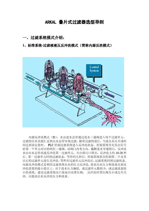
ARKAL 叠片式过滤器选型导则一、过滤系统模式介绍:1、标准系统-过滤液液压反冲洗模式(简称内源反洗模式)内源反冲洗模式(IS):水由进水总管通过进水三通阀进入每个过滤单元,过滤的出水直接汇总到出水总管实现过滤,随着过滤的进行,当进出水压差或时间达到设定值时, PLC控制过滤系统进入反冲洗状态,控制系统首先发出信号给第一个单元对应的两位三通阀,该阀门改变方向,截断进水导通排污,反冲洗水由出水总管高速反冲洗第一过滤单元,并由排污口排出,反冲洗大约10-20秒后,第一过滤单元回到过滤状态,等待约几秒后,控制系统依次控制第二个及其以后的过滤单元进行反冲洗,等所有过滤单元反冲洗后,过滤系统回到过滤状态。
内源反冲洗模式是利用过滤系统出水的压力反冲洗,要求出水压力和流量达到反冲洗需要的最小值以上,对于进水压力偏低,或过滤单元数较少,或过滤流量较小的系统,建议过滤系统出口处加自动背压阀,反冲洗时背压阀关小或完全关闭,以提高出水反冲洗压力和流量。
2、外源水力反冲洗模式(简称外源反洗模式)外源反冲洗模式(ES):水由进水总管通过进水三通阀进入每个过滤单元过滤,过滤的出水经过出水三通阀汇总到出水总管实现过滤,随着过滤的进行,当进出水压差或时间达到设定值时, PLC过滤系统进入反冲洗状态,控制系统首先发出信号给第一个单元对应的进出水两位三通阀,使两阀门改变方向,进水三通阀截断进水导通排污,出水三通阀截断出水导通外源水,反冲洗水由外源水管高速反冲洗第一过滤单元,并由排污口排出,反冲洗大约10-20秒后,第一过滤单元回到过滤状态,等待约几秒后,控制系统依次控制第二个及其以后的过滤单元进行反冲洗,等所有过滤单元反冲洗后,过滤系统回到过滤状态。
外源反冲洗模式应用于进水压力低,或过滤单元数太少,或过滤流量太小的应用点。
建议采用泵或其他压力清洁水源作为反冲洗外源,反冲洗外源的压力和流量需要达到规定值以上。
3、空气辅助反冲洗模式空气辅助反冲洗模式(AAF):对于2寸的过滤系统,ARKAL公司提供附加的水罐,通过压缩空气驱动水罐的水,并和水混合后,高速反冲洗每个过滤单元。
阿玛过滤机操作指导书1、目的:规范精炼操作工对加工设备的日常操作、正确使用,延长设备的使用寿命,提高产品质量和得率。
2、适应范围:精炼车间阿玛过滤机。
3、职责:3.1精炼车间操作工和精炼领班负责日常操作,并记录设备运行参数和工艺参数。
3.2精炼主管和工程部负责以此对操作者进行检查、监督。
4、名词解释:(略)5、程序:一、阿马过滤机的设计参数:设计温度:150℃、设计压力:6bar、过滤面积:60m2、吹干蒸气的供给:P、Фm为吹干蒸汽所需的流量,(2-3bar)、T(130-145℃);Фm=φmst×FOφmst:6-15kg/㎡.hr,F为过滤面积;O二、安全预防措施:(一)、普遍预防措施:1、所有的工作必须合符安全操作规则,预防意外的伤害;2、在生产或维护时期所有的安全设施必须运用;3、保持装配设备的干净与场所的洁净;4、保持热部件无杂物,因为高温油与蒸气易导致燃烧;5、在进行工作时,注意检查设备是否稍低于设定压力;6、打开盖时,确认没有人进入覆盖区域内;7、在进行关盖或其它部骤时,确认罐内无人与零碎杂物;(二)、电动元件:1、连结电器件前,检查它的使用电压,所有元件需要绝缘保护;2、检测预防重接,核实所有的设备已经被固定好;3、接地保护并进行短暂试运行;其它带电部分应绝缘隔离;4、以上必须遵守,直至整个安装与维护全部结束和所有的元件全部装运配好;(三)、马达的安全操作:1、所有转动部分要有保护装置,且没有其它附着物,预防部件丢失或撒落;2、确认马达已经被固定,检查旋转方向是否正确;3、马达驱动部件的连接是否水平均衡;(四)、压力安全生产控制:1、预防过滤的压力不要超出容器的设计压力,如果没有考虑负压,还得预防真空的形成;2、开始生产前,设备不能带压,气体与液体的线路应关闭;3、检查过滤机的压力表与压缩空气缓冲器的压力应稍小于设定的压力;4、阀门的安全:阀门使用前,确认管线无压,并且是空的;断开自动控制的电源;5、关闭空气的供应,确保阀门不能转动;6、当底阀打开时,不要把任何杂物投入罐内,以免卡住阀门或锥形漏斗;三、整套设备的安全生产操作:1、固定装置的场所具有的安全生产性:①、保持罐与罐、墙壁足够的距离,便于打开盖或进行其它工作;②、过滤元件的组装与拆卸必须垂直进行操作,保持上方有足够空间,因空间小或不够易造成金属网的损坏;③、过滤机下方有足够的空间进行拆卸底阀;2、过滤叶片的安全操作:①、叶片是过滤机的心脏部件,了解它的结构是必要的,它由空心框、铆钉、三层钢丝网组成,最外层为过滤层,中二层为导流层,起支撑作用,每叶片有一个喷嘴并带“O”密封圈,一个震动板并有系统编号;每叶片有一个固定的距离环,每个叶片可以单独取出;②、叶片的组装:安装前确认“O”密封圈的使用状态良好,用水或过滤液,或者相适应的润滑脂,减少喷溅嘴进入汇流槽的难度及“O”密封圈磨损机率,用手检查是否稳固地进入,然后才安装震动器件;③、叶片的组装顺序,应先安装最小的两片,然后安装稍大一点的两片,直到最中间的一片,然后安装距离环与震动杆;3、管线与阀门的安全生产性能:①、管线阀门的安装位置与尺寸必须与设计一致,尽量减少压力的损失;②、所有管线阀门的安装便于操作与维护工作的进行;③、消除固体聚集点,尤其是垂直管线;泵进口管需加大,以免抽空,否则对泵的运行及其过滤饼的稳固性有损害;罐液位的下降,对滤液的透明度也有负面的影响;④、泵与罐中间不能用闸阀,用蝶阀与隔膜阀、球阀较好,整个设备中的阀门开与关都不能太猛烈,各种气体供给需接单向阀,防止回流;⑤、注意过滤液体有可能从盖缘溢出,预防过滤清液回流,清油出口加接一个单向阀;4、附属部件安全生产巡视:①、过滤压力表的压力巡查,在罐顶部;出口的压力巡查,在清油出口,准确反映各段的不同压力;②、可调节部件的维护:ⅰ、震动器:a、组成(震动器、震动支撑、震动杆、卡式锁杆、空气驱动单元);b、需要的空气供应:空气干燥、干净并且加润滑剂;防止固液进入,减少磨损,润滑油的添加量为6~8滴/分;c、冷天,油雾化的空气会凝固,但不能用酒精去代替换,那样磨损更快速,可在调压器与气罐中间加一个冷冻器;d、工作的压力最大为6bar,震动压力太高会损害叶片,震动的频率由气压控制;e、震动杆的安装要正确,震动杆锁口朝上,连结震动器卡式锁杆口朝下,外卡套开口朝上;f、使用专用的工具,口径为50㎜,力矩最大为500Nm的开口呆板手;a时打开;P›0.8bar时关闭);b、滤筒清洗:用煤油或稀碱溶液进行滤筒与卡盘的清洗,避免用氯化产品和乙醇类产品进行清洗;c、压力的调节:锁扣向上为可调状态,向下为不可调状态,按箭头方向安装,调到所需的压力,由1/8″压力表可观察到;d、润滑器:它把润滑油雾化成2~20微米大小,调节添加量为(6~8滴/分);注意添加润滑油,不要超过筒子的限制线;它的清洗方法同滤筒的清洗方法相同;5、检测:①、安装部件检查:所有安装的附件、罐内外的结构与装备、金属外壳等是否适宜和固紧;②、清洁管与罐,并进行压力试验;用水进行试运行,检查过滤各程序的阀门使用状态;排空准备正常生产;③、最大的饼厚:运行的最大饼厚一定要在生产的条件下测得;运行参数记录(固体量、流速、温度),然后打开过滤机对饼厚进行测量,这样可以确定运行时间、压力和饼厚;注意:最大的饼厚不能超出叶片间距离的1/3。
•Steel•Energy and Utilities•Food and Beverages•Pulp and Paper•Water and Waste treatment•Mining, Minerals and PigmentsBenefits•Compact and robust design•Proven and reliable technology•Protection against clogging and fouling of downstreamequipment•Automatic backflush of filtered debris without interrupting the filtering process•Easy installation and low maintenance•High filtering capacity with low pressure drop •Customizable product to meet customer needs•High serviceabilityDesign and standard configurationThe ALF is designed to be placed directly in the pipe system in almost any position, horizontally or vertically. The filter can be regenerated at regular intervals without interrupting the filtering process. The regeneration process can be started either automatically or manually from a control panel, which can be installed close to the filter. The service opening is placed on the opposite side of the inlet, providing easy service access with no need to remove the filter from the pipe connection.Energy efficiency is in our DNAUp to 2.5% of the world’s CO2 emissions could be prevented if heat exchangers performed optimally. For information about how we accelerate our hunt for waste energy and help you save energy today, visit /energyhunter. Alfa Laval 360° Service PortfolioOur extensive service offering ensure top performance from your Alfa Laval equipment throughout its life cycle. The Alfa Laval 360 Service Portfolio include installation services, cleaning and repair as well as spare parts, technical documentation and trouble shooting. We also offer replacement, retrofit, integrity testing, monitoring and much more. For information about our complete service offering and how to contact us - please visit /service. General remarks for technical information•The global offering presented in this leaflet may not beavailable for all regions•All combinations may not be configurableDimensional drawingALF-B/EN13445ALF 15B 210 (8.3)567 (22.3)948 (37.3)ALF 20B 277 (10.9)649 (25.6)1107 (43.6)ALF 30B 375 (14.8)852 (33.5)1454 (57.2)ALF-P/EN13121ALF 10P 250 (9.8)530 (20.9)881 (34.7)ALF 15P 300 (11.8)685 (27.0)1155 (45.5)ALF 20P 350 (13.8)840 (33.1)1450 (57.1)ALF 30P 520 (20.5)1130 (44.5)1872 (73.7)ALF 40P 570 (22.4)1150 (45.3)2112 (83.1)ALF-R/EN13445ASME VIII,div. 1ALF 20R 325 (12.8)720 (28.3)1230 (48.4)ALF 30R 425 (16.7)950 (37.4)1606 (63.2)ALF 40R 500 (19.7)1150 (45.3)1961 (77.2)ALF 50R 600 (23.6)1400 (55.1)2370 (93.3)ALF 60R 700 (27.6)1650 (65.0)2595 (102.2)ALF 80R 905 (35.6)2082 (82.0)3728 (146.8)ALF-S/EN13445ASME VIII,div. 1ALF 10S 175 (6.9)450 (17.7)740 (29.1)ALF 15S 250 (9.8)595 (23.4)978 (38.5)ALF 20S 300 (11.8)720 (28.3)1230 (48.4)ALF 30S400 (15.7)950 (37.4)1612 (63.5)Dimensions may vary depending on the flange connection type and whether the orientation of the filter is vertical or horizontal.ASME U-designator available on request.Technical dataFilter bodyALF-BA516 Gr70 or equivalentALF-P Fiberglass reinforced polyester (FRP)ALF-R Rubber-lined carbon steel EN P265GH/ASTM A516 Gr60ALF-S Stainless Steel EN 1.4404/ASTM 316LBasketPerforated plateStainless steel, Super stainless steel (SMO),TitaniumWedge wireStainless steel, Duplex, Super DuplexPerforated plate design (0.04, 0.06, 0.08, 0.1)Wedge wire design 0.1, 0.3, 0.5, 1.0(0.004, 0.01, 0.02, 0.04)Control Voltage 24 VDCActuators operation Pneumatic / Electric Protection class IP65Filters controlled1 to 4ATEX certification available on request.Operational dataALF-P 10 (150)50.0 (122.0)ALF-R 10 (150)65.0 (149.0)ALF-S10 (150)65.0 (149.0)ALF-15100 (440)310 (1364)ALF-20180 (792)550 (2420)ALF-30400 (1760)1240 (5456)ALF-40700 (3080)2210 (9724)ALF-501110 (4840)3450 (15180)ALF-601600 (7040)5000 (22000)ALF-802800 (12320)8840 (38896)Recommended pressure drop and capacity range.Extended pressure and temperature design available on request.ALF-P EN1092–1 type 11 PN10ASME B16.5, Class 150100–400 (4-16)ALF-R EN1092–1 type 11 PN10ASME B16.5, Class 150ASME B16.47, Series B Class 150200–800 (8-32)ALF-SEN1092–1 type 02 PN10ASME B16.5, Class 150100–300 (4-12)This document and its contents are subject to copyrights and other intellectual property rights owned by Alfa Laval AB (publ) or any of its affiliates (jointly “Alfa Laval”). No part of this document may be copied, re-produced or transmitted in any form or by any means, or for any purpose, without Alfa Laval’s prior express written permission. Information and services provided in this document are made as a benefit and service to the user, and no representations or warranties are made about the accuracy or suitability of this information and these services for any purpose. All rights are reserved.200007629-2-EN-GB© Alfa Laval AB How to contact Alfa LavalUp-to-date Alfa Laval contact details for all countries are always availableon our website at 。
Compressed air filtersCOMMITTED TO SUPERIOR PRODUCTIVITYIn-house development & testingSince 1998, our dedicated filtration team is responsible for in-house development of cutting-edge filtration solutions. This results in expert know-how of filtration mechanisms, state-of-the-art test facilities and breakthrough innovations. For many years, our filtration team has cooperated closely with the University of Karlsruhe, a leading institute in research of filtration mechanisms.Rigorous quality controlTo ensure the highest standards, all Atlas Copco products are subjected to rigorous quality control testing. The entire filter range is produced in-house, on the most advanced production lines, using the most stringent methods in the industry. You can rest assured at all times that strict certification and testing procedures are conducted to ensure our filtration products meet the highest standards.Cast design6 grades 13 sizes 9 → 550 l/s19 → 1,200 cfm850 → 1,100 l/s 1,801 →DDp+H Dry dust Oil aerosol Wet dust Oil vaporWater dropsMicro-organisms m eCERTIFIED PERFORMANCEAtlas Copco filters are qualified according to the ISO 8573-1:2010 standard. This is the latest edition of the standard. Beware of filters that comply with earlier editions, such as ISO 8573-1:1991 or ISO 8573-1:2001. The difference is inferior quality of the delivered compressed air. This qualification is a result of our filters being tested according to ISO 12500-1:2007, ISO 12500-2:2007, and ISO 12500-3:2009. These specify the test layout, test procedures and inlet conditions required for testing coalescing filters, vapor filters, and solid particle filters used in compressed air systems, to determine their effectiveness in removing oil aerosol, oil vapor and solid particles. The measurements of the air purity downstream the filter for each specific contaminant have been performed according to the test methods described in respectively ISO 8573-2:2007, ISO 8573-5:2001 and ISO 8573-4:2001. Tests have been conducted in-house as well as in external labs, and are independently validated by TÜV.ISO certificationAtlas Copco’s filters have been fully tested and qualified according to the following ISO standards:Certified peace of mind• ISO 8573-1:2010: Compressed air - Contaminants and purity classes• ISO 8573-2:2007: Compressed air - Test method for oil aerosol content• ISO 8573-4:2001: Compressed air - Test method for dust• ISO 8573-5: 2001: Compressed air - Test method for oil vapor and organic solvent content• ISO 12500-1:2007: Filters for compressed air - test methods - oil aerosols• ISO 12500-2:2007: Filters for compressed air - test methods - oil vapors• ISO 12500-3:2009: Filters for compressed air - test methods - particulatesA SOLUTION FOR EVERY APPLICATIONAt different points of use, different compressed air purities might be needed, depending on the application. The various air purity classes are provided in the table below, which clearly shows the various Atlas Copco filters and dryers that meet all the different classes.* Please contact your Atlas Copco sales representative.UD+ SERIESTwo-in-one oil coalescing filters with supreme energy savingsUD+ filters efficiently reduce oil aerosol, wet dust and water drops in your compressed air stream to protect your investment, equipmentand processes. The UD+ combines two filtration steps (DD+ and PD+) into one, a unique technology to meet the high-quality requirements of diverse applications and provide ultimate energy savings.PerformanceSave spaceapplications where space is at a premium.Save moneyto conventional filters.* Inlet oil concentration = 10 mg/m³. Oil = oil aerosol and liquid.• EWD electronic drain with no loss of compressed air and , F and larger).Wall mounting kitCBACCBAAB850+T & 1100+T 9+ – 550+550+F – 8000+FDD(+)/PD(+) SERIESHigh performance oil coalescing filtersDD(+) and PD(+) filters efficiently reduce oil aerosol, wet dust and water drops in your compressed airstream. These could come from the lubrication of the compressor element, the intake air, and the compressor installation itself. These innovative filtration solutions are engineered to cost-effectively provide the best air purity and meet today’s increasing quality demands.Easy maintenanceMonitoring of energy use* Inlet oil concentration = 10 mg/m³. Oil = oil aerosol and liquid.Performance850+T & 1100+T 9+ – 550+550+F – 8000+FAB(EWD is optional on sizes 10+ - 550+ l/s and 12-690 l/s; standard on sizes ≥550F).EWD electronic drain• Multiply the nominal capacity of the selected filter with the corresponding correction CCCBBAADDp(+)/PDp(+) SERIESOptimal dry dust filtrationDDp(+) and PDp(+) filters efficiently prevent dust,particulates and micro-organisms arising from corrosion,dirt and adsorption material from entering yourcompressed air stream. These innovative filtrationsolutions are engineered to cost-effectively providethe best air purity and meet today’s increasingquality demands.Easy maintenanceMonitoring of energy use PerformanceVoltage-free contactCCBBAAC9+ – 550+550+F – 8000+F850+T & 1100+T ABQDT SERIESActivated carbon towers for optimal oil vapor filtrationThe high efficiency activated carbon tower is capable of removing hydrocarbons, odors and oil vapor from compressed air.The activated carbon will, by the use of adsorption,reduce the residual oil content to lower than 0.003 mg/m³.The pressure drop is low and stays minimal during the filter’s lifetime.Performance* After UD+ or DD+/PD+ with inlet oil concentration of 10 mg/m³.CertificationISO 8573-5:2001AABBCCUD+ & QDT: the winning combinationUD+For other compressed air inlet pressures, please multiply the filter capacity by the following correction factor (Kp):QDT 20-310QD(+) SERIESHigh performance oil vapor filtersQD(+) filters efficiently reduce hydrocarbons, odors and oilvapor in your compressed air stream to protect your investment, equipment and processes. The activated carbon layers will, by the use of adsorption, reduce the residual oil content to less than 0.003 mg/m³. The pressure drop is lowand stays minimal during the lifetime of the filter.* After UD+ or DD(+)/PD(+) with inlet oil concentration of 10 mg/m³.PerformanceOptions(DD & PD only).SFA SERIESSilicone-free removal of oil aerosol, dust and oil vaporSuperb air purity is a prerequisite to safeguard your instruments and end product. Our silicone-free SFA filters efficiently prevent dry and wet dust, particulates, oil aerosol and water drops from entering your compressed air system. The SFA series is manufactured and treated according to the high standards of silicone-free equipment, and certified bythe Fraunhofer Institute as guaranteed silicone-free.* Nominal pressure: 7 bar(e)/102 psig; temperature: 20°C, 68°F.• Painting • AutomotiveThe performance of the SFA filters is comparable to the performance of the + range filters (please refer to pages 8, 10 and 14).CABH SERIESGuaranteed air purity up to 350 barHigh pressure filters efficiently reduce oil aerosol, dust and wet dust, particulates, water droplets and oil vapor in your compressed air stream to protect your investment, equipment and processes. Our innovative high pressure filtration solutions are engineered to cost effectivelyprovide the best air purity and meet today’s increasing quality demands up to working pressures of 350 bar. All high pressure filter housings are hydraulically tested to ensure safe and reliable operation at all times. A pressure test certificate accompanies each filter.Applications• Chemical• Food & beverage • Manufacturing • Military • Oil & gasPerformanceAlways install a liquid water separation system in front of a filter. Water separation is not needed in the high pressure line if there is a sufficiently low PDP in the low pressure line (e.g. nitrogen skid, low pressure line with adsorption dryer).* Inlet oil concentration = 10 mg/m³. Oil = oil aerosol and liquid.** After DD(+)/PD(+) with inlet oil concentration of 10 mg/m³.DDH, DDHp, PDH, PDHp, QDH20 bar Aluminum50 bar Aluminum1250+1725+1925+3200+50 bar Stainless Steel1000+1700+2040+3400+100 bar Stainless Steel1200+1700+Example• Working pressure 300 bar(g), compressed air flow 500 m³/h.• Multiply the nominal capacity of the selected filter with thecorresponding correction factor at the required working pressure to obtain the capacity at working pressure:- Size 510+: 510 m³/h * 0.96 = 490 m³/h => the 510+ filter sizeis not large enough.- Size 750+: 750 m³/h * 0.96 = 720 m³/h => the 750+ filter sizeis the size to select.CBAMV SERIESMedical vacuum filters for optimal protectionof man and machineMedical vacuum filters are installed at the inlet of the vacuum pump toremove any liquid, solid or bacterial contamination which could damagethe vacuum pump and biologically infect the downstream air.Our innovative medical vacuum filtration solutions complywith HTM medical standards.Performance* In accordance with BS 3928-1969.Applications• Medical• Dental• VeterinaryCorrection factorsB CA Drain flask2935 0932 44 © 2018, A t l a s C o p c o A i r p o w e r N V , B e l g i u m . A l l r i g h t s r e s e r v e d . D e s i g n s a n d s p e c i fi c a t i o n s a r e s u b j e c t t o c h a n g e w i t h o u t n o t i c t i o n . R e a d a l l s a f e t y i n s t r u c t i o n s i n t h e m a n u a l b e f o r e u s a g e .。
Arkal BMF过滤系统日期:二OO七年一月上海乐泽环境工程有限公司目录公司简介 (3)1. BMF结构和组成 (4)2.设备的运行说明 (5)3. 系统性能及参数描述 (6)4. BMF与无阀滤池的比较 (8)5. 系统的安装、运行和维护费用 (9)6. 应用案例: (11)公司简介上海乐泽环境工程有限公司是以色列ARKAL过滤系统公司授权中国华东地区总代理。
产品主要应用于钢铁、化工、电力、造纸、纺织、医药、食品等行业。
现主要的客户有:钢铁:宝钢、重庆钢铁、首都钢铁……中石油:抚顺石化、吉化石油乙烯项目、独山子大炼油项目……中石化:洛阳石化、镇海炼化……煤化工:神华煤制油、神木化学………………有着丰富的经验。
由于优化的设计方案、高品质的产品以及良好的技术支持和售后服务,得到客户的信赖。
1. BMF结构和组成1.1 外壳: BMF外壳采用碳钢内外防腐1.2布水装置:三个上开口布水,简单、均匀、可靠;1.3集水装置:采用精加工开缝的不锈钢集水器,均匀,强度高,精加工的楔缝最小可为0.15毫米。
1.4 滤料:匀质海砂,过滤器无衬托层,采用单一滤料。
1.5 控制器:Arkal BMF专用控制器1.6 阀门:系统采用Arkal配套的电动或气动阀门,阀门控制系统稳定,维护少。
2.设备的运行说明2.1过滤状态(举例3000T/h的系统,采用BMF96-15,下同)BMF96-15过滤系统含有15个BMF96过滤单元,原水由进水总管进入后通过进水电动蝶阀进入每个过滤单元进行过滤,清洁液由每个过滤单元出来后,汇总到出水总管后流出,完成过滤过程。
2.2反洗状态随着过滤的进行,过滤系统的压差慢慢上升,当达到设定反冲压差时(或反冲间隔时间),系统进入反冲过程。
此时出口电动阀门关闭,出水只从出口旁路通过,然后第一个过滤单元的进水电动阀关闭,截断进口总管和第一过滤单元,排污电动阀打开导通出水管和排污管。
由于出水有压力,而排污管没有压力,所以高压的水将对第一个过滤单元进行反冲洗,反洗在设定的时间完成后,进水电动阀门打开,排污电动蝶阀关闭,第一个单元重新进入过滤状态,然后第2,3,4……单元依次反洗, 反冲洗全部完成后,出口电动阀门重新打开,系统再回到过滤状态。