零件的参数设计-97A
- 格式:ppt
- 大小:642.00 KB
- 文档页数:31
ANSI/AGMA 1106-A97ANSI/AGMA 1006-A97米制单位版美国国家标准塑料齿轮齿形尺寸AGMA标准美国国家标准塑料齿轮齿形尺寸ANSI/AGMA 1106-A97(ANSI/AGMA 1006-A97 米制单位版)美国国家标准的批准,需要由美国全国标准学会审核,查明标准编制部门业已达到应履行的程序、一致同意和其他审批准则的要求。
当根据美国全国标准学会标准评审委员会的裁决,涉及直接利害和物质利害关系方业已达成相当多数同意时,一致同意即告成立。
相当多数同意表示比简单多数要多得多,但不一定无异议。
一致同意要求一切观点和异议均加以考虑,并协同努力达成彼此的消解。
美国国家标准的采用纯属志愿性的;不拘是否赞同该标准,国家标准的实行毫不妨碍任何人不遵照它开展制造、营销、采购,或运用产品、方法或程序等活动。
美国全国标准学会不制订标准,也决不对任何美国国家标准作解释。
此外,无人有权或被授权以美国全国标准学会的名义,发表对美国国家标准的解释。
有关对本标准解释的要求,应该发送给美国齿轮制造商协会。
指示:AGMA(美国齿轮制造商协会)技术出版物依发展经历而定,持续进行改进、修订或撤销。
一切参阅任何AGMA技术出版物的人员,应该查明该出版物应是能从该协会取得的该论题最新版本。
[可以引用或摘录表格或其他内容独立的段落。
应注明文献出处,格式如下:承出版者美国齿轮制造商协会(the American Gear Manufacturers Association,1500 King Street ,Suite 201,Alexandria,Virginia 22314)许可,摘录自ANSI/AGMA 1106-A97“塑料齿轮齿形尺寸”(Tooth Proportions for Plastic Gears)]批准日期1997年8月7日摘要本标准介绍一种新版基本齿条AGMA PT,此新版基本齿条采取全圆型齿根圆角,可以在塑料制齿轮的许多应用场合优先选用。


数学建模中的图论方法一、引言我们知道,数学建模竞赛中有问题A和问题B。
一般而言,问题A是连续系统中的问题,问题B是离散系统中的问题。
由于我们在大学数学教育内容中,连续系统方面的知识的比例较大,而离散数学比例较小。
因此很多人有这样的感觉,A题入手快,而B题不好下手。
另外,在有限元素的离散系统中,相应的数学模型又可以划分为两类,一类是存在有效算法的所谓P类问题,即多项式时间内可以解决的问题。
但是这类问题在MCM中非常少见,事实上,由于竞赛是开卷的,参考相关文献,使用现成的算法解决一个P类问题,不能显示参赛者的建模及解决实际问题能力之大小;还有一类所谓的NP问题,这种问题每一个都尚未建立有效的算法,也许真的就不可能有有效算法来解决。
命题往往以这种NPC问题为数学背景,找一个具体的实际模型来考验参赛者。
这样增加了建立数学模型的难度。
但是这也并不是说无法求解。
一般来说,由于问题是具体的实例,我们可以找到特殊的解法,或者可以给出一个近似解。
图论作为离散数学的一个重要分支,在工程技术、自然科学和经济管理中的许多方面都能提供有力的数学模型来解决实际问题,所以吸引了很多研究人员去研究图论中的方法和算法。
应该说,我们对图论中的经典例子或多或少还是有一些了解的,比如,哥尼斯堡七桥问题、中国邮递员问题、四色定理等等。
图论方法已经成为数学模型中的重要方法。
许多难题由于归结为图论问题被巧妙地解决。
而且,从历年的数学建模竞赛看,出现图论模型的频率极大,比如:AMCM90B-扫雪问题;AMCM91B-寻找最优Steiner树;AMCM92B-紧急修复系统的研制(最小生成树)AMCM94B-计算机传输数据的最小时间(边染色问题)CMCM93B-足球队排名(特征向量法)CMCM94B-锁具装箱问题(最大独立顶点集、最小覆盖等用来证明最优性)CMCM98B-灾情巡视路线(最优回路)等等。
这里面都直接或是间接用到图论方面的知识。
要说明的是,这里图论只是解决问题的一种方法,而不是唯一的方法。


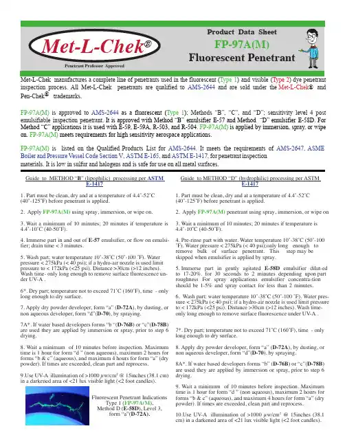
) dye penetrant inspection process. All Met-L-Chek penetrants are qualified to AMS-2644 and are sold under the Met-L-Chek ® and Pen-Chek ® trademarks.FP-97A(M) is approved to AMS-2644 as a fluorescent (Type 1); Methods “B”, “C”, and “D”; sensitivity level 4 post emulsifiable inspection penetrant . It is approved with Method “B” emulsifier E-57 and Method “D” emulsifier E-58D. For Method “C” applications it is used with E-59, E-59A, R-503, and R-504. FP-97A(M) is applied by immersion, spray, or wipe on. FP-97A(M) meets requirements for high sensitivity aerospace applications.FP-97A(M) is listed on the Qualified Products List for AMS-2644. It meets the requirements of AMS-2647, ASME Boiler and Pressure Vessel Code Section V , ASTM E-165, and ASTM E-1417, for penetrant inspectionmaterials. It is low in sulfur and halogens and is safe for use on all metal surfaces.Fluorescent Penetrant Guide to METHOD “B ” (lipophilic) processing per ASTM E-14171.Part must be clean, dry and at a temperature of 4.4˚-52˚C (40˚-125˚F) before penetrant is applied.2.Apply FP-97A(M) using spray, immersion, or wipe on.3.Wait a minimum of 10 minutes; 20 minutes if temperature is4.4˚-10˚C (40-50˚F).4.Immerse part in and out of E-57 emulsifier, or flow on emulsi -fier; drain time < 3 minutes.5.Wash part; water temperature 10˚-38˚C (50˚-100 ˚F). Water pressure < 275kPa (< 40 psi); if a hydro-air nozzle is used limit pressure to < 172kPa (<25 psi). Distance >30cm (>12 inches). Wash time- only long enough to remove surface fluorescence un -der UV-A .6*. Dry part; temperature not to exceed 71˚C (160˚F), time - only long enough to dry surface.7.Apply dry powder developer, form “a” (D-72A ), by dusting, or non aqueous developer, form “d”(D-70), by spraying.7A*. If water based developers forms “b “(D-76B ) or “c”(D-78B )are used they are applied by immersion or spray, prior to step 6 drying.8.Wait a minimum of 10 minutes before inspection. Maximum time is 1 hour for form “d ” (non aqueous), maximum 2 hours for forms “b & c” (aqueous), and maximum 4 hours for form “a” (dry powder). If times are exceeded, clean part and e UV-A illumination of >1000 µw/cm 2 @ 15inches (38.1 cm)in a darkened area of <21 lux visible light (<2 foot candles).Fluorescent Penetrant Indications Type 1 (FP-97A(M ), Method D (E-58D ), Level 3, form “a”(D-72A).Guide to METHOD “D” (hydrophilic) processing per ASTM E-14171.Part must be clean, dry and at a temperature of 4.4˚-52˚C (40˚-125˚F) before penetrant is applied.2. Apply FP-97A(M) penetrant using spray, immersion, or wipe on 3.Wait a minimum of 10 minutes; 20 minutes if temperature is 4.4˚-10˚C (40-50˚F). 4.Pre-rinse part with water. Water temperature 10˚-38˚C (50˚-100˚F). Water pressure < 275kPa (< 40 psi);only long enough to remove bulk of surface penetrant. This step may be skipped when emulsifier is applied by spray.5.Immerse part in gently agitated E-58D emulsifier dilut -ed to 17-20%. for 30 seconds to 2 minutes depending upon part roughness For spray applications emulsifier concentra -tion should be 1-5% and spray contact for less than 2 minutes.6.Wash part; water temperature 10˚-38˚C (50˚-100 ˚F). Water pres -sure < 275kPa (< 40 psi); if a hydro-air nozzle is used limit pressure to < 172kPa (<25 psi). Distance >30cm (>12 inches). Wash time- only long enough to remove surface fluorescence under UV-A .7*. Dry part; temperature not to exceed 71˚C (160˚F), time - only long enough to dry surface.8.Apply dry powder developer, form “a” (D-72A ), by dusting, or non aqueous developer, form “d”(D-70), by spraying.8A*. If water based developers forms “b” (D-76B ) or “c”(D-78B )are used they are applied by immersion or spray, prior to step 6 drying.9.Wait a minimum of 10 minutes before inspection. Maximum time is 1 hour for form “d ” (non aqueous), maximum 2 hours for forms “b & c” (aqueous), and maximum 4 hours for form “a” (dry powder). If times are exceeded, clean part and e UV-A illumination of >1000 µw/cm 2 @ 15inches (38.1cm)in a darkened area of <21 lux visible light (<2 foot candles).Product AvailabilityTypical Physical Properties Fluorescent PenetrantUnited States McGean Phone: +1-216-441-4900Fax: +1-216-441-1377United Kingdom M cGean UK Phone: +44-1902-456563Fax: +44-1902-457443Singapore McGean Singapore Phone: +65-6863-2296Fax: +65-6863-2297BEFORE USING ANY OF THESE PRODUCTS, YOU MUST BECOME COMPLETELY FAMILIAR WITH THE INFORMATION CONTAINED IN MCGEAN’S SAFETY DATA SHEETS. All information contained therein or in this document regarding handling, personal protection, and other safety measures must be followed during use. McGean presents the information herein without warranty and disclaims any liability, including any consequential, special, or indirect damages, arising from its use and misuse. Because the use, the conditions of use, product or product composition, and/or applicable laws may differ from one location to another and/or may change with time, the purchaser and/or user is solely responsible for determining whether the product is appropriate for use. McGean recommends use of this product solely in commercial processes which are specified by McGean and which do not violate any third-party patent rights or any laws or regulations or otherwise adversely impact human health and the environment. Users must make their own investigations and determine the suitability of the product for their particular purposes. McGean does not guarantee the accuracy of any data provided by its suppliers. MCGEAN MAKES NO WARRANTIES, EXPRESS OR IMPLIED, INCLUDING, BUT NOT LIMITED TO, THE IMPLIED WARRANTIES OF MERCHANTABILITY AND FITNESS FOR A PARTICULAR PURPOSE EXCEPT AS EXPRESSLY STATED IN THE SELLER’S SALES CONTRACT OR SALES ACKNOWLEDGEMENT FORM. USE OF ANY MCGEAN PRODUCT IS AT THE USER’S RISK. Contact UsForm: yellow green liquid Density: 964 g/L Flash Point: > 93˚C (> 200˚F)Viscosity 8.9 mm 2/s Fluorescent Brightness: (AMS-2644 requirement > 90%): 107.5 % Corrosion of aluminum: none Corrosion of carbon steel: none Corrosion of magnesium: none Corrosion of stainless steel: none Corrosion of titanium: none Chloride content: < 100 ppm (0.01%)Fluoride content: < 50 ppm (0.005%)Sodium content: < 100 ppm (0.01%)Sulfur content: < 100 ppm (0.01%)Mercury: none VOC’s: 0 g/L Ozone layer depleting substances: none PCB’s: noneSpecificationsISO-3452AMS-2644 AMS-2647 ASTM E-165 ASTM E-1417RR RPS-702-7 R-R Omat # 651D BAC 5423 HONEYWELL EMS 52309P&W PMC #4353Snecma sensibilité S3ASME B & PV code Sec V6 x 1 pint (0.4L) can with dauber 1 gallon (3.7L) plastic bottle 5 gallon (18.9L) plastic jug with our spout 55 gallon (208L) plastic drum。

Designation:D149–97a(Reapproved2004)An American National Standard Standard Test Method forDielectric Breakdown Voltage and Dielectric Strength ofSolid Electrical Insulating Materials at Commercial Power Frequencies1This standard is issued under thefixed designation D149;the number immediately following the designation indicates the year oforiginal adoption or,in the case of revision,the year of last revision.A number in parentheses indicates the year of last reapproval.Asuperscript epsilon(e)indicates an editorial change since the last revision or reapproval.This standard has been approved for use by agencies of the Department of Defense.1.Scope1.1This test method covers procedures for the determina-tion of dielectric strength of solid insulating materials at commercial power frequencies,under specified conditions.2,3 1.2Unless otherwise specified,the tests shall be made at60 Hz.However,this test method may be used at any frequency from25to800Hz.At frequencies above800Hz,dielectric heating may be a problem.1.3This test method is intended to be used in conjunction with any ASTM standard or other document that refers to this test method.References to this document should specify the particular options to be used(see5.5).1.4It may be used at various temperatures,and in any suitable gaseous or liquid surrounding medium.1.5This test method is not intended for measuring the dielectric strength of materials that arefluid under the condi-tions of test.1.6This test method is not intended for use in determining intrinsic dielectric strength,direct-voltage dielectric strength, or thermal failure under electrical stress(see Test Method D3151).1.7This test method is most commonly used to determine the dielectric breakdown voltage through the thickness of a test specimen(puncture).It may also be used to determine dielec-tric breakdown voltage along the interface between a solid specimen and a gaseous or liquid surrounding medium(flash-over).With the addition of instructions modifying Section12, this test method may be used for proof testing.1.8This test method is similar to IEC Publication243-1.All procedures in this method are included in IEC243-1.Differ-ences between this method and IEC243-1are largely editorial.1.9This standard does not purport to address all of the safety concerns,if any,associated with its use.It is the responsibility of the user of this standard to establish appro-priate safety and health practices and determine the applica-bility of regulatory limitations prior to use.Specific hazard statements are given in Section7.Also see6.4.1.2.Referenced Documents2.1ASTM Standards:4D374Test Methods for Thickness of Solid Electrical Insu-lationD618Practice for Conditioning Plastics for TestingD877Test Method for Dielectric Breakdown V oltage of Insulating Liquids Using Disk ElectrodesD1711Terminology Relating to Electrical InsulationD2413Practice for Preparation of Insulating Paper and Board Impregnated with a Liquid DielectricD3151Test Method for Thermal Failure of Solid Electrical Insulating Materials Under Electric StressD3487Specification for Mineral Insulating Oil Used in Electrical ApparatusD5423Specification for Forced-Convection Laboratory Ovens for Electrical Insulation2.2IEC Standard:Pub.243-1Methods of Test for Electrical Strength of Solid Insulating Materials—Part1:Tests at Power Frequencies51This test method is under the jurisdiction of ASTM Committee D09on Electrical and Electronic Insulating Materials and is the direct responsibility of Subcommittee D09.12on Electrical Tests.Current edition approved March1,2004.Published March2004.Originally approved st previous edition approved in1997as D149–97a.2Bartnikas,R.,Chapter3,“High V oltage Measurements,”Electrical Propertiesof Solid Insulating Materials,Measurement Techniques,V ol.IIB,Engineering Dielectrics,R.Bartnikas,Editor,ASTM STP926,ASTM,Philadelphia,1987.3Nelson,J.K.,Chapter5,“Dielectric Breakdown of Solids,”Electrical Properties of Solid Insulating Materials:Molecular Structure and Electrical Behavior,V ol.IIA,Engineering Dielectrics,R.Bartnikas and R.M.Eichorn, Editors,ASTM STP783,ASTM,Philadelphia,1983.4For referenced ASTM standards,visit the ASTM website,,or contact ASTM Customer Service at service@.For Annual Book of ASTM Standards volume information,refer to the standard’s Document Summary page on the ASTM website.5Available from the International Electrotechnical Commission,Geneva,Swit-zerland.1Copyright©ASTM International,100Barr Harbor Drive,PO Box C700,West Conshohocken,PA19428-2959,United States. --`,`,`,,``,`,,```,`,,,```,,-`-`,,`,,`,`,,`---2.3ANSI Standard:C68.1Techniques for Dielectric Tests,IEEE Standard No.463.Terminology 3.1Definitions:3.1.1dielectric breakdown voltage (electric breakdown voltage),n —the potential difference at which dielectric failure occurs under prescribed conditions in an electrical insulating material located between two electrodes.(See also Appendix X1.)3.1.1.1Discussion —The term dielectric breakdown voltage is sometimes shortened to “breakdown voltage.”3.1.2dielectric failure (under test),n —an event that is evidenced by an increase in conductance in the dielectric under test limiting the electric field that can be sustained.3.1.3dielectric strength ,n —the voltage gradient at which dielectric failure of the insulating material occurs under spe-cific conditions of test.3.1.4electric strength ,n —see dielectric strength.3.1.4.1Discussion —Internationally,“electric strength”is used almost universally.3.1.5flashover ,n —a disruptive electrical discharge at the surface of electrical insulation or in the surrounding medium,which may or may not cause permanent damage to the insulation.3.1.6For definitions of other terms relating to solid insulat-ing materials,refer to Terminology D 1711.4.Summary of Test Method4.1Alternating voltage at a commercial power frequency (60Hz,unless otherwise specified)is applied to a test specimen.The voltage is increased from zero or from a level well below the breakdown voltage,in one of three prescribed methods of voltage application,until dielectric failure of the test specimen occurs.4.2Most commonly,the test voltage is applied using simple test electrodes on opposite faces of specimens.The specimens may be molded or cast,or cut from flat sheet or plate.Other electrode and specimen configurations may be used to accom-modate the geometry of the sample material,or to simulate a specific application for which the material is being evaluated.5.Significance and Use5.1The dielectric strength of an electrical insulating mate-rial is a property of interest for any application where an electrical field will be present.In many cases the dielectric strength of a material will be the determining factor in the design of the apparatus in which it is to be used.5.2Tests made as specified herein may be used to provide part of the information needed for determining suitability of a material for a given application;and also,for detecting changes or deviations from normal characteristics resulting from pro-cessing variables,aging conditions,or other manufacturing orenvironmental situations.This test method is useful for process control,acceptance or research testing.5.3Results obtained by this test method can seldom be used directly to determine the dielectric behavior of a material in an actual application.In most cases it is necessary that these results be evaluated by comparison with results obtained from other functional tests or from tests on other materials,or both,in order to estimate their significance for a particular material.5.4Three methods for voltage application are specified in Section 12:Method A,Short-Time Test;Method B,Step-by-Step Test;and Method C,Slow Rate-of-Rise Test.Method A is the most commonly-used test for quality-control tests.How-ever,the longer-time tests,Methods B and C,which usually will give lower test results,may give more meaningful results when different materials are being compared with each other.If a test set with motor-driven voltage control is available,the slow rate-of-rise test is simpler and preferable to the step-by-step test.The results obtained from Methods B and C are comparable to each other.5.5Documents specifying the use of this test method shall also specify:5.5.1Method of voltage application,5.5.2V oltage rate-of-rise,if slow rate-of-rise method is specified,5.5.3Specimen selection,preparation,and conditioning,5.5.4Surrounding medium and temperature during test,5.5.5Electrodes,5.5.6Wherever possible,the failure criterion of the current-sensing element,and5.5.7Any desired deviations from the recommended proce-dures as given.5.6If any of the requirements listed in 5.5are missing from the specifying document,then the recommendations for the several variables shall be followed.5.7Unless the items listed in 5.5are specified,tests made with such inadequate reference to this test method are not in conformance with this test method.If the items listed in 5.5are not closely controlled during the test,the precisions stated in 15.2and 15.3may not be realized.5.8Variations in the failure criteria (current setting and response time)of the current sensing element significantly affect the test results.5.9Appendix X1.contains a more complete discussion of the significance of dielectric strength tests.6.Apparatus6.1Voltage Source —Obtain the test voltage from a step-up transformer supplied from a variable sinusoidal low-voltage source.The transformer,its voltage source,and the associated controls shall have the following capabilities:6.1.1The ratio of crest to root-mean-square (rms)test voltage shall be equal to =265%(1.34to 1.48),with the test specimen in the circuit,at all voltages greater than 50%of the breakdown voltage.6.1.2The capacity of the source shall be sufficient to maintain the test voltage until dielectric breakdown occurs.For most materials,using electrodes similar to those shown in Table 1,an output current capacity of 40mA is usually satisfactory.For more complex electrode structures,or for6Available from American National Standards Institute (ANSI),25W.43rd St.,4th Floor,New York,NY10036.2testing high-loss materials,higher current capacity may be needed.The power rating for most tests will vary from0.5kV A for testing low-capacitance specimens at voltages up to10kV, to5kV A for voltages up to100kV.6.1.3The controls on the variable low-voltage source shall be capable of varying the supply voltage and the resultant test voltage smoothly,uniformly,and without overshoots or tran-sients,in accordance with12.2.Do not allow the peak voltage to exceed1.48times the indicated rms test voltage under any circumstance.Motor-driven controls are preferable for making short-time(see12.2.1)or slow-rate-of-rise(see12.2.3)tests.6.1.4Equip the voltage source with a circuit-breaking device that will operate within three cycles.The device shall disconnect the voltage-source equipment from the power service and protect it from overload as a result of specimen breakdown causing an overload of the testing apparatus.If prolonged current follows breakdown it will result in unnec-essary burning of the test specimens,pitting of the electrodes, and contamination of any liquid surrounding medium.6.1.5The circuit-breaking device should have an adjustable current-sensing element in the step-up transformer secondary, to allow for adjustment consistent with the specimen charac-teristics and arranged to sense specimen current.Set the sensing element to respond to a current that is indicative of specimen breakdown as defined in12.3.6.1.6The current setting can have a significant effect on the test results.Make the setting high enough that transients,such as partial discharges,will not trip the breaker but not so high that excessive burning of the specimen,with resultant electrode damage,will occur on breakdown.The optimum current setting is not the same for all specimens and depending upon the intended use of the material and the purpose of the test,it may be desirable to make tests on a given sample at more than one current setting.The electrode area may have a significanteffect upon what the current setting should be.6.1.7The specimen current-sensing element may be in theprimary of the step-up transformer.Calibrate the current-sensing dial in terms of specimen current.6.1.8Exercise care in setting the response of the currentcontrol.If the control is set too high,the circuit will notrespond when breakdown occurs;if set too low,it may respondto leakage currents,capacitive currents,or partial discharge(corona)currents or,when the sensing element is located in theprimary,to the step-up transformer magnetizing current.6.2Voltage Measurement—A voltmeter must be providedfor measuring the rms test voltage.A peak-reading voltmetermay be used,in which case divide the reading by=2to get rms values.The overall error of the voltage-measuring circuitshall not exceed5%of the measured value.In addition,theresponse time of the voltmeter shall be such that its time lagwill not be greater than1%of full scale at any rate-of-riseused.6.2.1Measure the voltage using a voltmeter or potentialtransformer connected to the specimen electrodes,or to aseparate voltmeter winding,on the test transformer,that isunaffected by the step-up transformer loading.6.2.2It is desirable for the reading of the maximum appliedtest voltage to be retained on the voltmeter after breakdown sothat the breakdown voltage can be accurately read and re-corded.6.3Electrodes—For a given specimen configuration,thedielectric breakdown voltage may vary considerably,depend-ing upon the geometry and placement of the test electrodes.Forthis reason it is important that the electrodes to be used bedescribed when specifying this test method,and that they bedescribed in the report.TABLE1Typical Electrodes for Dielectric Strength Testing of Various Types of Insulating Materials AA These electrodes are those most commonly specified or referenced in ASTM standards.With the exception of Type5electrodes,no attempt has been made to suggest electrode systems for other thanflat surface material.Other electrodes may be used as specified in ASTM standards or as agreed upon between seller and purchaser where none of these electrodes in the table is suitable for proper evaluation of the material being tested.B Electrodes are normally made from either brass or stainless steel.Reference should be made to the standard governing the material to be tested to determine which, if either,material is preferable.C The electrodes surfaces should be polished and free from irregularities resulting from previous testing.D Refer to the appropriate standard for the load force applied by the upper electrode assembly.Unless otherwise specified the upper electrodes shall be5062g.E Refer to the appropriate standard for the proper gap settings.F The Type6electrodes are those given in IEC Publication243-1for testing offlat sheet materials.They are less critical as to concentricity of the electrodes than are the Types1and2electrodes.G Other diameters may be used,provided that all parts of the test specimen are at least15mm inside the edges of the electrodes.H The Type7electrodes,as described in the table and in Note G,are those given in IEC Publication243-1for making tests parallel to the surface.36.3.1One of the electrodes listed in Table1should be specified by the document referring to this test method.If no electrodes have been specified,select an applicable one from Table1,or use other electrodes mutually acceptable to the parties concerned when the standard electrodes cannot be used due to the nature or configuration of the material being tested. See references in Appendix X2for examples of some special electrodes.In any event the electrodes must be described in the report.6.3.2The electrodes of Types1through4and Type6of Table1should be in contact with the test specimen over the entireflat area of the electrodes.6.3.3The specimens tested using Type7electrodes should be of such size that all portions of the specimen will be within and no less than15mm from the edges of the electrodes during test.In most cases,tests using Type7electrodes are made with the plane of the electrode surfaces in a vertical position.Tests made with horizontal electrodes should not be directly com-pared with tests made with vertical electrodes,particularly when the tests are made in a liquid surrounding medium. 6.3.4Keep the electrode surfaces clean and smooth,and free from projecting irregularities resulting from previous tests. If asperities have developed,they must be removed.6.3.5It is important that the original manufacture and subsequent resurfacing of electrodes be done in such a manner that the specified shape andfinish of the electrodes and their edges are maintained.Theflatness and surfacefinish of the electrode faces must be such that the faces are in close contact with the test specimen over the entire area of the electrodes. Surfacefinish is particularly important when testing very thin materials which are subject to physical damage from improp-erlyfinished electrodes.When resurfacing,do not change the transition between the electrode face and any specified edge radius.6.3.6Whenever the electrodes are dissimilar in size or shape,the one at which the lowest concentration of stress exists,usually the larger in size and with the largest radius, should be at ground potential.6.3.7In some special cases liquid metal electrodes,foil electrodes,metal shot,water,or conductive coating electrodes are used.It must be recognized that these may give results differing widely from those obtained with other types of electrodes.6.3.8Because of the effect of the electrodes on the test results,it is frequently possible to obtain additional informa-tion as to the dielectric properties of a material(or a group of materials)by running tests with more than one type of electrode.This technique is of particular value for research testing.6.4Surrounding Medium—The document calling for this test method should specify the surrounding medium and the test temperature.Sinceflashover must be avoided and the effects of partial discharges prior to breakdown mimimized, even for short time tests,it is often preferable and sometimes necessary to make the tests in insulating liquid(see6.4.1). Breakdown values obtained in insulating liquid may not be comparable with those obtained in air.The nature of the insulating liquid and the degree of previous use may influence the test values.Testing in air may require excessively large specimens or cause heavy surface discharges and burning before breakdown.Some electrode systems for testing in air make use of pressure gaskets around the electrodes to prevent flashover.The material of the gaskets or seals around the electrodes may influence the breakdown values.6.4.1When tests are made in insulating oil,an oil bath of adequate size shall be provided.(Caution—The use of glass containers is not recommended for tests at voltages above about10kV,because the energy released at breakdown may be sufficient to shatter the container.Metal baths must be grounded.)It is recommended that mineral oil meeting the requirements of Specification D3487,Type I or II,be used.It should have a dielectric breakdown voltage as determined by Test Method D877of at least26kV.Other dielectricfluids may be used as surrounding mediums if specified.These include,but are not limited to,siliconefluids and other liquids intended for use in transformers,circuit breakers,capacitors,or cables.6.4.1.1The quality of the insulating oil may have an appreciable effect upon the test results.In addition to the dielectric breakdown voltage,mentioned above,particulate contaminants are especially important when very thin speci-mens(25µm(1mil)or less)are being tested.Depending upon the nature of the oil and the properties of the material being tested,other properties,including dissolved gas content,water content,and dissipation factor of the oil may also have an effect upon the results.Frequent replacement of the oil,or the use offilters and other reconditioning equipment may be necessary to minimize the effect of variations of the quality of the oil on the test results.6.4.1.2Breakdown values obtained using liquids having different electrical properties may not be comparable.(See X1.4.7.)If tests are to be made at other than room temperature, the bath must be provided with a means for heating or cooling the liquid,and with a means to ensure uniform temperature. Small baths can in some cases be placed in an oven(see6.4.2) in order to provide temperature control.If forced circulation of thefluid is provided,care must be taken to prevent bubbles from being whipped into thefluid.The temperature shall be maintained within65°C of the specified test temperature at the electrodes,unless otherwise specified.In many cases it is specified that specimens to be tested in insulating oil are to be previously impregnated with the oil and not removed from the oil before testing(see Practice D2413).For such materials,the bath must be of such design that it will not be necessary to expose the specimens to air before testing.6.4.2If tests in air are to be made at other than ambient temperature or humidity,an oven or controlled humidity chamber must be provided for the tests.Ovens meeting the requirements of Specification D5423and provided with means for introducing the test voltage will be suitable for use when only temperature is to be controlled.6.4.3Tests in gasses other than air will generally require the use of chambers that can be evacuated andfilled with the test gas,usually under some controlled pressure.The design of such chambers will be determined by the nature of the test program to beundertaken. 46.5Test Chamber —The test chamber or area in which the tests are to be made shall be of sufficient size to hold the test equipment,and shall be provided with interlocks to prevent accidental contact with any electrically energized parts.A number of different physical arrangements of voltage source,measuring equipment,baths or ovens,and electrodes are possible,but it is essential that (1)all gates or doors providing access to spaces in which there are electrically energized parts be interlocked to shut off the voltage source when opened;(2)clearances are sufficiently large that the field in the area of the electrodes and specimen are not distorted and that flashovers and partial discharges (corona)do not occur except between the test electrodes;and (3)insertion and replacement of specimens between tests be as simple and convenient as possible.Visual observation of the electrodes and test specimen during the test is frequently desirable.7.Hazards7.1Warning —Lethal voltages may be present during this test.It is essential that the test apparatus,and all associated equipment that may be electrically connected to it,be properly designed and installed for safe operation.Solidly ground all electrically conductive parts that any person might come into contact with during the test.Provide means for use at the completion of any test to ground any parts which:were at high voltage during the test;may have acquired an induced charge during the test;may retain a charge even after disconnection of the voltage source.Thoroughly instruct all operators in the proper way to conduct tests safely.When making high-voltage tests,particularly in compressed gas or in oil,the energy released at breakdown may be sufficient to result in fire,explosion,or rupture of the test chamber.Design test equip-ment,test chambers,and test specimens so as to minimize the possibility of such occurrences and to eliminate the possibility of personal injury.7.2Warning —Ozone is a physiologically hazardous gas at elevated concentrations.The exposure limits are set by gov-ernmental agencies and are usually based upon recommenda-tions made by the American Conference of Governmental Industrial Hygienists.7Ozone is likely to be present whenever voltages exist which are sufficient to cause partial,or complete,discharges in air or other atmospheres that contain oxygen.Ozone has a distinctive odor which is initially discernible at low concentrations but sustained inhalation of ozone can cause temporary loss of sensitivity to the scent of ozone.Because of this it is important to measure the concentration of ozone in the atmosphere,using commercially available monitoring devices,whenever the odor of ozone is persistently present or when ozone generating conditions e appropriate means,such as exhaust vents,to reduce ozone concentrations to acceptable levels in working areas.8.Sampling8.1The detailed sampling procedure for the material being tested should be defined in the specification for that material.8.2Sampling procedures for quality control purposes should provide for gathering of sufficient samples to estimate both the average quality and the variability of the lot being examined;and for proper protection of the samples from the time they are taken until the preparation of the test specimens in the laboratory or other test area is begun.8.3For the purposes of most tests it is desirable to take samples from areas that are not immediately adjacent to obvious defects or discontinuities in the material.The outer few layers of roll material,the top sheets of a package of sheets,or material immediately next to an edge of a sheet or roll should be avoided,unless the presence or proximity of defects or discontinuities is of interest in the investigation of the material.8.4The sample should be large enough to permit making as many individual tests as may be required for the particular material (see 12.4).9.Test Specimens9.1Preparation and Handling :9.1.1Prepare specimens from samples collected in accor-dance with Section 8.9.1.2When flat-faced electrodes are to be used,the surfaces of the specimens which will be in contact with the electrodes shall be smooth parallel planes,insofar as possible without actual surface machining.9.1.3The specimens shall be of sufficient size to prevent flashover under the conditions of test.For thin materials it may be convenient to use specimens large enough to permit making more than one test on a single piece.9.1.4For thicker materials (usually more than 2mm thick)the breakdown strength may be high enough that flashover or intense surface partial discharges (corona)may occur prior to breakdown.Techniques that may be used to prevent flashover,or to reduce partial discharge (corona)include:9.1.4.1Immerse the specimen in insulating oil during the test.See X1.4.7for the surrounding medium factors influenc-ing breakdown.This may be necessary for specimens that have not been dried and impregnated with oil,as well as for those which have been prepared in accordance with Practice D 2413,for example.(See 6.4.)9.1.4.2Machine a recess or drill a flat-bottom hole in one or both surfaces of the specimen to reduce the test thickness.If dissimilar electrodes are used (such as Type 6of Table 1)and only one surface is to be machined,the larger of the two electrodes should be in contact with the machined surface.Care must be taken in machining specimens not to contaminate or mechanically damage them.9.1.4.3Apply seals or shrouds around the electrodes,in contact with the specimen to reduce the tendency to flashover.9.1.5Materials that are not in flat sheet form shall be tested using specimens (and electrodes)appropriate to the material and the geometry of the sample.It is essential that for these materials both the specimen and the electrodes be defined in the specification for the material.9.1.6Whatever the form of the material,if tests of other than surface-to-surface puncture strength are to be made,define the specimens and the electrodes in the specification for the material.7Available from the American Conference of Governmental Industrial Hygien-ists,Building No.D-7,6500Glenway Ave.,Cincinnati,OH45211.5。