表面粗糙度最新国家标注
- 格式:ppt
- 大小:1.53 MB
- 文档页数:56
新国标表面粗糙度标注符号英文回答:As for the new national standard for surface roughness symbols, it is essential to understand the significance of these symbols in engineering and manufacturing industries. Surface roughness symbols are used to communicate the desired surface finish of a part or component. They provide a visual representation of the texture and quality of a surface, helping manufacturers and engineers achieve the desired level of precision and performance in their products.In the new national standard, surface roughness symbols are typically represented by a combination of letters, numbers, and symbols. For example, a common surface roughness symbol might be expressed as "Ra 0.8 μm." Inthis case, "Ra" stands for the arithmetic mean roughness value, while "0.8 μm" represents the actual roughness value in micrometers.Understanding these symbols is crucial for ensuringthat the surface finish of a part meets the required specifications. For instance, in industries like automotive manufacturing, aerospace engineering, and medical device production, achieving the right surface roughness is essential for ensuring the proper functioning and longevity of the final product. Without proper surface roughness symbols, manufacturers may struggle to meet quality standards and customer expectations.In my experience, I have encountered situations where a lack of clarity around surface roughness symbols has led to misunderstandings and production delays. For example, a supplier once delivered a batch of components with a surface finish that did not meet the specified roughness requirements. This oversight resulted in costly rework and delayed delivery to our customers.Therefore, it is crucial for engineers, designers, and manufacturers to be well-versed in interpreting and applying surface roughness symbols according to the newnational standard. By doing so, they can ensure that their products meet the necessary quality standards and performance criteria.中文回答:对于新的国家标准中的表面粗糙度标注符号,了解这些符号在工程和制造行业中的重要性至关重要。
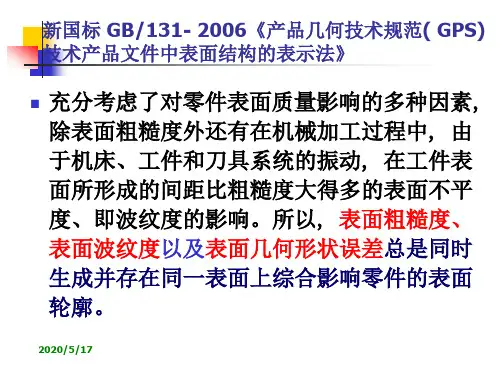

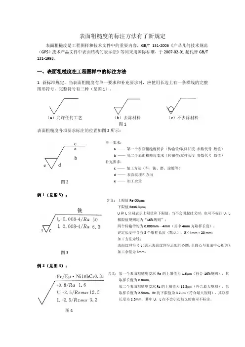
表面粗糙度的标注方法有了新规定表面粗糙度是工程图样和技术文件中的重要内容,GB/T 131‐2006《产品几何技术规范(GPS )技术产品文件中表面结构的表示法》等同采用国际标准,于2007‐02‐01起代替GB/T 131‐1993。
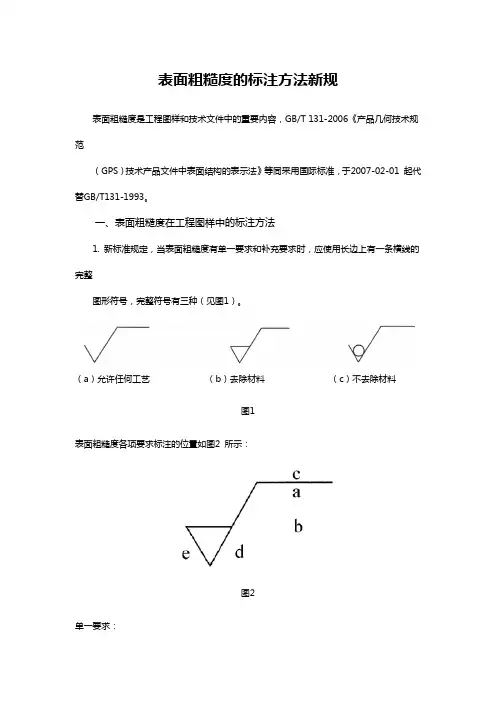
一、表面粗糙度在工程图样中的标注方法1. 新标准规定,当表面粗糙度有单一要求和补充要求时,应使用长边上有一条横线的完整图形符号,完整符号有三种(见图1)。
(a )允许任何工艺 (b )去除材料 (c )不去除材料图1表面粗糙度各项要求标注的位置如图2所示:图2例1(见图3):图3例2(见图4):图4例3(传输带/取样长度为默认值,评定长度中所含取样长度的个数不是默认的5,而是含有3个取样长度,见图5):图5例4(见图6):图62. 表面粗糙度的注写和读取方向要与尺寸的注写和读取方向一致(见图7),并标注在轮廓线上(轮廓线的延长线上)或指引线上(见图8和图9)。
图7 图8(a ) (b )图93. 必要时也可标注在特征尺寸的尺寸线上(见图10和图11)或形位公差的框格上(见图12)。
图10(a) (b)图11(a) (b)图124. 当多个表面有相同要求或图纸空间有限时,可采用简化注法(见图13~图15)。
注:图示的表面粗糙度符号是指对图形中封闭轮廓的周边六个面的共同要求(不包括前后面)。
图13(a) (b)注:多数表面有相同要求,可统一标注在标题栏的附近,而不是标注在图形的右上角。
图14(a)(b)注:用带字母或不带字母的图形符号,以等式的形式注写在图形或标题栏附近。
图155. 两种或多种工艺获得的同一表面的注法(见图16)。
注:同时给出镀覆前后的表面粗糙度要求的注法。
图16二、标注表面粗糙度以前应弄清楚的几个问题1. 什么是传输带/取样长度?其具体数值是多少?在图样上如何标注?在什么情况下可不标注?2. 什么是评定长度?它与取样长度有什么关系?在图样上如何标注?在什么情况下可不标注?3. 极限值的两个判断规则是什么?在图样上如何表示?4. 单向极限和双向极限在图样上如何表示?在什么情况下可省略“U”、“L”?5. Rz的含义是什么?它与原Ry是什么关系?参考资料GB/T 131-2006产品几何技术规范(GPS)技术产品文件中表面结构的表示法李震、崔长德 2007-05-20。
中华人民共和国国家标准UDC 744 43机械制图GB 131-83表面粗糙度代号及其注法代替GB 131-74Mechanical drawingsSurface reoughness symbols andmethods of indicating1 引言1.1 本标准规定了零件表面粗糙度代〔符〕号及其在图样上的注法。
图样上所标注的表面粗糙度代〔符〕号,是该表面完工后的要求。
有关表面粗糙度的各项规定应按功能要求给定。
若仅需要加工但对表面粗糙度的其它规定没有要求时,可以只注表面粗糙度符号。
1.2 本标准等效采用国际标准ISO 1302-1978《图样上表面特征的表示法》。
1.3 与本标准有关的国家标准:GB 3505-83《表面粗糙度术语表面及其参数》GB 1031-83《表面粗糙度参数及其数值》2 表面粗糙度代〔符〕号2.1 图样上表示零件表面粗糙度的符号见表1。
表12.2 表面粗糙度高度参数轮廓算术平均偏差Ra值的标注见表2,Ra在代号中用数值表示(单位为微米)。
表22.3 其他表面粗糙度高度参数,轮廓微观不平度十点高度Rz、轮廓最大高度Ry值(单位为微米)的标注见表3,参数值前需标注出相应的符号。
表3续表32.4 取样长度应标注在符号长边的线下面,见图1。
若按GB 1031附录B中表B1、B2选用对应的取样长度时,在图样上可省略标注。
图32.7 在符号长边的横线上面也可以注写镀涂或其它表面处理的要求。
需要表示镀涂或其它表面处理后的表面粗糙度值时,标注方法见图4a。
需要表示镀涂前的表面粗糙度值时,应另加说明,见图4b。
若同时要求表示镀涂前及镀涂后的表面粗糙度值时,标注方法如图4c。
图42.8 需要控制表面加工纹理方向时,可在符号的右边加注加工纹理方向符号,见图5。
常见的加工纹理方向符号见表4。
图6 表4续表4注:若表中所列符号不能清楚地表明所要求的纹理方向,应在图样上用文字说明。
2.10 表面粗糙度符号的画法见图7。
表面粗糙度的标注方法新规表面粗糙度是工程图样和技术文件中的重要内容,GB/T 131‐2006《产品几何技术规范(GPS)技术产品文件中表面结构的表示法》等同采用国际标准,于2007‐02‐01 起代替GB/T131‐1993。
一、表面粗糙度在工程图样中的标注方法1. 新标准规定,当表面粗糙度有单一要求和补充要求时,应使用长边上有一条横线的完整图形符号,完整符号有三种(见图1)。
(a)允许任何工艺(b)去除材料(c)不去除材料图1表面粗糙度各项要求标注的位置如图2 所示:图2单一要求:a ——第一个表面粗糙度要求(传输带/取样长度参数代号数值)b ——第二个表面粗糙度要求(传输带/取样长度参数代号数值)补充要求:c ——加工方法(车、铣、磨、涂镀等)d ——表面纹理和方向e ——加工余量例1(见图3):图3含义:上限值Ra=50μm;下限值Ra=6.3μm;U 和L 分别表示上限值和下限值,当不会引起歧义时,也可不标注U、L;极限值规则均为“16%规则”;两个传输带均为0.008mm—4mm(其中4mm 为取样长度);评定长度中含有5 个取样长度(默认),5×4mm = 20 mm;加工方法为铣;表面纹理符号c(表示表面纹理呈近似同心圆,且圆心与表面中心相关);加工余量为3mm。
例2(见图4):图4含义:第一个表面粗糙度要求Ra 的上限值为1.6μm(符合16%规则),其取样长度为0.8mm;第二个表面粗糙度要求Rz 的上限值为12.5μm(符合最大规则),其取样长度为2.5mm,Rz 的下限值为3.2μm(符合最大规则),其取样长度为2.5mm,其中U、L 在不会引起歧义时也可不标注。
例3(传输带/取样长度为默认值,评定长度中所含取样长度的个数不是默认的5,而是含有3 个取样长度,见图5):图5含义:传输带/取样长度为默认值;评定长度为3 个取样长度;默认Rz 为上限值要求,Rz = 6.3μm,符合最大规则。
§7–4 零件的技术要求一、表面结构的表示法1.表面结构的基本概念 (1)概述为了保证零件的使用性能,在机械图样中需要对零件的表面结构给出要求。
表面结构就是由粗糙度轮廓、波纹度轮廓和原始轮廓构成的零件表面特征。
(2)表面结构的评定参数评定零件表面结构的参数有轮廓参数、图形参数和支承率曲线参数。
其中轮廓参数分为三种:R 轮廓参数(粗糙度参数)、W 轮廓参数(波纹度参数)和P 轮廓参数(原始轮廓参数)。
机械图样中,常用表面粗糙度参数Ra 和Rz 作为评定表面结构的参数。
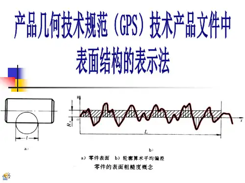
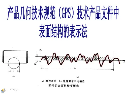
① 轮廓算术平均偏差Ra 它是在取样长度lr 内,纵坐标Z(x )(被测轮廓上的各点至基准线x 的距离)绝对值的算术平均值,如图7-14所示。
可用下式表示:dx x Z lr Ra lr⎰=0)(1② 轮廓最大高度Rz 它是在一个取样长度内,最大轮廓峰高与最大轮廓谷深之和,如图7-14 所示。
图7-14 Ra 、Rz 参数示意图国家标准GB/T1031-2009给出的Ra 和Rz 系列值如表7-1所示。
表7-1 Ra 、Rz 系列值 m μRa Rz Ra Rz 0.012 6.3 6.3 0.025 0.025 12.5 12.5 0.05 0.05 25 25 0.1 0.1 50 50 0.2 0.2 100 100 0.4 0.4 200 0.8 0.8 400 1.6 1.6 800 3.23.216002.标注表面结构的图形符号(1)图形符号及其含义在图样中,可以用不同的图形符号来表示对零件表面结构的不同要求。
标注表面结构的图形符号及其含义如表7-2所示。
表7-2 表面结构图形符号及其含义符号名称符号样式含义及说明基本图形符号未指定工艺方法的表面;基本图形符号仅用于简化代号标注,当通过一个注释解释时可单独使用,没有补充说明时不能单独使用扩展图形符号用去除材料的方法获得表面,如通过车、铣、刨、磨等机械加工的表面;仅当其含义是“被加工表面”时可单独使用用不去除材料的方法获得表面,如铸、锻等;也可用于保持上道工序形成的表面,不管这种状况是通过去除材料或不去除材料形成的完整图形符号在基本图形符号或扩展图形符号的长边上加一横线,用于标注表面结构特征的补充信息工件轮廓各表面图形符号当在某个视图上组成封闭轮廓的各表面有相同的表面结构要求时,应在完整图形符号上加一圆圈,标注在图样中工件的封闭轮廓线上。
§7–4 零件的技术要求一、表面结构的表示法1.表面结构的基本概念 (1)概述为了保证零件的使用性能,在机械图样中需要对零件的表面结构给出要求。
表面结构就是由粗糙度轮廓、波纹度轮廓和原始轮廓构成的零件表面特征。
(2)表面结构的评定参数评定零件表面结构的参数有轮廓参数、图形参数和支承率曲线参数。
其中轮廓参数分为三种:R 轮廓参数(粗糙度参数)、W 轮廓参数(波纹度参数)和P 轮廓参数(原始轮廓参数)。
机械图样中,常用表面粗糙度参数Ra 和Rz 作为评定表面结构的参数。
① 轮廓算术平均偏差Ra 它是在取样长度lr 内,纵坐标Z(x )(被测轮廓上的各点至基准线x 的距离)绝对值的算术平均值,如图7-14所示。
可用下式表示:dx x Z lr Ra lr⎰=0)(1② 轮廓最大高度Rz 它是在一个取样长度内,最大轮廓峰高与最大轮廓谷深之和,如图7-14 所示。
图7-14 Ra 、Rz 参数示意图国家标准GB/T1031-2009给出的Ra 和Rz 系列值如表7-1所示。
表7-1 Ra 、Rz 系列值 m μRaRzRaRz0.012 6.3 6.3 0.025 0.025 12.5 12.5 0.05 0.05 25 25 0.1 0.1 50 50 0.2 0.2 100 100 0.4 0.4 200 0.8 0.8 400 1.6 1.6 800 3.23.216002.标注表面结构的图形符号(1)图形符号及其含义在图样中,可以用不同的图形符号来表示对零件表面结构的不同要求。
标注表面结构的图形符号及其含义如表7-2所示。
表7-2 表面结构图形符号及其含义符号名称符号样式含义及说明基本图形符号未指定工艺方法的表面;基本图形符号仅用于简化代号标注,当通过一个注释解释时可单独使用,没有补充说明时不能单独使用扩展图形符号用去除材料的方法获得表面,如通过车、铣、刨、磨等机械加工的表面;仅当其含义是“被加工表面”时可单独使用用不去除材料的方法获得表面,如铸、锻等;也可用于保持上道工序形成的表面,不管这种状况是通过去除材料或不去除材料形成的完整图形符号在基本图形符号或扩展图形符号的长边上加一横线,用于标注表面结构特征的补充信息工件轮廓各表面图形符号当在某个视图上组成封闭轮廓的各表面有相同的表面结构要求时,应在完整图形符号上加一圆圈,标注在图样中工件的封闭轮廓线上。
表面结构的图样表示法加工零件时,由于刀具在零件表面上留下刀痕和切削分裂时表面金属的塑性变形等影响,使零件表面存在着间距较小的轮廓峰谷。
这种表面上具有较小间距的峰谷所组成的微观几何形状特性,称为表面粗糙度。
机器设备对零件各个表面的要求不一样,如配合性质、耐磨性、抗腐蚀性、密封性、外观要求等,因此,对零件表面粗糙度的要求也各有不同。
一般说来,凡零件上有配合要求或有相对运动的表面,表面粗糙度参数值小。
因此,应在满足零件表面功能的前提下,合理选用表面粗糙度参数。
1.评定表面结构常用的轮廓参数①算术平均偏差Ra是指在一个取样长度内纵坐标值Z(x)绝对值的算术平均值② 轮廓的最大高度Rz是指在同一取样长度内,最大轮廓峰高和最大轮廓谷深之和的高度图9-27 评定表面结构常用的轮廓参数2.有关检验规范的基本术语检验评定表面结构参数值必须在特定条件下进行。
国家标准规定,图样中注写参数代号及其数值要求的同时,还应明确其检验规范。
有关检验规范方面的基本术语有取样长度、评定长度、滤波器和传输带以及极限值判断规则。
本有关检验规范仅介绍取样长度与评定长度和极限值判断规则。
(1)取样长度和评定长度以粗糙度高度参数的测量为例,由于表面轮廓的不规则性,测量结果与测量段的长度密切相关,当测量段过短,各处的测量结果会产生很大差异,但当测量段过长,则测得的高度值中将不可避免地包含了波纹度的幅值。
因此,在X轴上选取一段适当长度进行测量,这段长度称为取样长度。
但是,在每一取样长度内的测得值通常是不等的,为取得表面粗糙度最可靠的值,一般取几个连续的取样长度进行测量,并以各取样长度内测量值的平均值作为测得的参数值。
这段在X轴方向上用于评定轮廓的并包含着一个或几个取样长度的测量段称为评定长度。
当参数代号后未注明时,评定长度默认为5 个取样长度,否则应注明个数。
例如:Rz0.4、Ra30.8、Rz13.2分别表示评定长度为5个(默认)、3个、1个取样长度。
表面粗糙度的标注方法有了新规定——华科大教师团队内部资料表面粗糙度是工程图样和技术文件中的重要内容,GB/T 131‐2006《产品几何技术规范(GPS)技术产品文件中表面结构的表示法》等同采用国际标准,于2007‐02‐01 起代替GB/T131‐1993。
一、表面粗糙度在工程图样中的标注方法1. 新标准规定,当表面粗糙度有单一要求和补充要求时,应使用长边上有一条横线的完整图形符号,完整符号有三种(见图1)。
(a)允许任何工艺(b)去除材料(c)不去除材料图1表面粗糙度各项要求标注的位置如图2 所示:图2单一要求:a ——第一个表面粗糙度要求(传输带/取样长度参数代号数值)b ——第二个表面粗糙度要求(传输带/取样长度参数代号数值)补充要求:c ——加工方法(车、铣、磨、涂镀等)d ——表面纹理和方向e ——加工余量例1(见图3):图3含义:上限值Ra=50μm;下限值Ra=6.3μm;U 和L 分别表示上限值和下限值,当不会引起歧义时,也可不标注U、L;极限值规则均为“16%规则”;两个传输带均为0.008mm—4mm(其中4mm 为取样长度);评定长度中含有5 个取样长度(默认),5×4mm = 20 mm;加工方法为铣;表面纹理符号c(表示表面纹理呈近似同心圆,且圆心与表面中心相关);加工余量为3mm。
例2(见图4):图4含义:第一个表面粗糙度要求Ra 的上限值为1.6μm(符合16%规则),其取样长度为0.8mm;第二个表面粗糙度要求Rz 的上限值为12.5μm(符合最大规则),其取样长度为2.5mm,Rz 的下限值为3.2μm(符合最大规则),其取样长度为2.5mm,其中U、L 在不会引起歧义时也可不标注。
例3(传输带/取样长度为默认值,评定长度中所含取样长度的个数不是默认的5,而是含有3 个取样长度,见图5):图5含义:传输带/取样长度为默认值;评定长度为3 个取样长度;默认Rz 为上限值要求,Rz = 6.3μm,符合最大规则。