磁共振无线充电技术鼻祖级文章英文原文
- 格式:docx
- 大小:248.01 KB
- 文档页数:8
Wireless Power Transfer via Strongly Coupled Magnetic ResonancesAndré Kurs,1* Aristeidis Karalis,2 Robert Moffatt,1 J. D. Joannopoulos,1 Peter Fisher,3Marin Soljačić11Department of Physics, Massachusetts Institute of Technology, Cambridge, MA 02139, USA. 2Department of Electrical Engineering and Computer Science, Massachusetts Institute of Technology, Cambridge, MA 02139, USA. 3Department of Physics and Laboratory for Nuclear Science, Massachusetts Institute of Technology, Cambridge, MA 02139, USA.*To whom correspondence should be addressed. E-mail: akurs@Using self-resonant coils in a strongly coupled regime, we experimentally demonstrate efficient non-radiative power transfer over distances of up to eight times the radius of the coils. We demonstrate the ability to transfer 60W with approximately 40% efficiency over distances in excess of two meters. We present a quantitative model describing the power transfer which matches the experimental results to within 5%. We discuss practical applicability and suggest directions for further studies. At first glance, such power transfer is reminiscent of the usual magnetic induction (10); however, note that the usual non- resonant induction is very inefficient for mid-range applications.Overview of the formalism. Efficient mid-range power transfer occurs in particular regions of the parameter space describing resonant objects strongly coupled to one another. Using coupled-mode theory to describe this physical system (11), we obtain the following set of linear equationsIn the early 20th century, before the electrical-wire grid, Nikola Tesla (1) devoted much effort towards schemes to a&m(t)=(iωm-Γm)a m(t)+∑iκmn a n(t)+F m(t)n≠m(1)transport power wirelessly. However, typical embodiments (e.g. Tesla coils) involved undesirably large electric fields. During the past decade, society has witnessed a dramatic surge of use of autonomous electronic devices (laptops, cell- phones, robots, PDAs, etc.) As a consequence, interest in wireless power has re-emerged (2–4). Radiative transfer (5), while perfectly suitable for transferring information, poses a number of difficulties for power transfer applications: the efficiency of power transfer is very low if the radiation is omnidirectional, and requires an uninterrupted line of sight and sophisticated tracking mechanisms if radiation is unidirectional. A recent theoretical paper (6) presented a detailed analysis of the feasibility of using resonant objects coupled through the tails of their non-radiative fields for mid- range energy transfer (7). Intuitively, two resonant objects of the same resonant frequency tend to exchange energy efficiently, while interacting weakly with extraneous off- resonant objects. In systems of coupled resonances (e.g. acoustic, electro-magnetic, magnetic, nuclear, etc.), there is often a general “strongly coupled” regime of operation (8). If one can operate in that regime in a given system, the energy transfer is expected to be very efficient. Mid-range power transfer implemented this way can be nearly omnidirectional and efficient, irrespective of the geometry of the surrounding space, and with low interference and losses into environmental objects (6).Considerations above apply irrespective of the physical nature of the resonances. In the current work, we focus on one particular physical embodiment: magnetic resonances (9). Magnetic resonances are particularly suitable for everyday applications because most of the common materials do not interact with magnetic fields, so interactions with environmental objects are suppressed even further. We were able to identify the strongly coupled regime in the system of two coupled magnetic resonances, by exploring non-radiative (near-field) magnetic resonant induction at MHzfrequencies. where the indices denote the different resonant objects. The variables a m(t) are defined so that the energy contained in object m is |a m(t)|2, ωm is the resonant frequency of thatisolated object, and Γm is its intrinsic decay rate (e.g. due to absorption and radiated losses), so that in this framework anuncoupled and undriven oscillator with parameters ω0 and Γ0 would evolve in time as exp(iω0t –Γ0t). The κmn= κnm are coupling coefficients between the resonant objects indicated by the subscripts, and F m(t) are driving terms.We limit the treatment to the case of two objects, denoted by source and device, such that the source (identified by the subscript S) is driven externally at a constant frequency, and the two objects have a coupling coefficient κ. Work is extracted from the device (subscript D) by means of a load (subscript W) which acts as a circuit resistance connected to the device, and has the effect of contributing an additional term ΓW to the unloaded device object's decay rate ΓD. The overall decay rate at the device is therefore Γ'D= ΓD+ ΓW. The work extracted is determined by the power dissipated in the load, i.e. 2ΓW|a D(t)|2. Maximizing the efficiency η of the transfer with respect to the loading ΓW, given Eq. 1, is equivalent to solving an impedance matching problem. One finds that the scheme works best when the source and the device are resonant, in which case the efficiency isThe efficiency is maximized when ΓW/ΓD= (1 + κ2/ΓSΓD)1/2. It is easy to show that the key to efficient energy transfer is to have κ2/ΓSΓD> 1. This is commonly referred to as the strongcoupling regime. Resonance plays an essential role in thisDS S D'' power transfer mechanism, as the efficiency is improved by approximately ω2/ΓD 2 (~106 for typical parameters) compared to the case of inductively coupled non-resonant objects. Theoretical model for self-resonant coils. Ourexperimental realization of the scheme consists of two self- resonant coils, one of which (the source coil) is coupled inductively to an oscillating circuit, while the other (the device coil) is coupled inductively to a resistive load (12) (Fig. 1). Self-resonant coils rely on the interplay between distributed inductance and distributed capacitance to achieve resonance. The coils are made of an electrically conducting wire of total length l and cross-sectional radius a wound into Given this relation and the equation of continuity, one finds that the resonant frequency is f 0 = 1/2π[(LC )1/2]. We can now treat this coil as a standard oscillator in coupled-mode theory by defining a (t ) = [(L /2)1/2]I 0(t ).We can estimate the power dissipated by noting that the sinusoidal profile of the current distribution implies that the spatial average of the peak current-squared is |I 0|2/2. For a coil with n turns and made of a material with conductivity σ, we modify the standard formulas for ohmic (R o ) and radiation (R r ) µ0ω l a helix of n turns, radius r , and height h . To the best of our knowledge, there is no exact solution for a finite helix in the literature, and even in the case of infinitely long coils, the solutions rely on assumptions that are inadequate for our R o = 2σ 4πa µ πωr 42 ωh 2 (6)system (13). We have found, however, that the simple quasi- R =0 n 2 + (7)static model described below is in good agreementr ε 12 c3π3 c(approximately 5%) with experiment.We start by observing that the current has to be zero at the ends of the coil, and make the educated guess that the resonant modes of the coil are well approximated bysinusoidal current profiles along the length of the conducting wire. We are interested in the lowest mode, so if we denote by s the parameterization coordinate along the length of the conductor, such that it runs from -l /2 to +l /2, then the time- dependent current profile has the form I 0 cos(πs /l ) exp(i ωt ). It follows from the continuity equation for charge that the linear charge density profile is of the form λ0 sin(πs /l ) exp(i ωt ), so the two halves of the coil (when sliced perpendicularly to its axis) contain charges equal in magnitude q 0 = λ0l /π but opposite in sign.As the coil is resonant, the current and charge density profiles are π/2 out of phase from each other, meaning that the real part of one is maximum when the real part of the other is zero. Equivalently, the energy contained in the coil is 0The first term in Eq. 7 is a magnetic dipole radiation term(assuming r << 2πc /ω); the second term is due to the electric dipole of the coil, and is smaller than the first term for our experimental parameters. The coupled-mode theory decay constant for the coil is therefore Γ = (R o + R r )/2L , and its quality factor is Q = ω/2Γ.We find the coupling coefficient κDS by looking at the power transferred from the source to the device coil,assuming a steady-state solution in which currents and charge densities vary in time as exp(i ωt ).P =⎰d rE (r )⋅J (r ) =-⎰d r (A&S (r )+∇φS (r ))⋅J D (r ) at certain points in time completely due to the current, and at other points, completely due to the charge. Usingelectromagnetic theory, we can define an effective inductance L and an effective capacitance C for each coil as follows:=-1⎰⎰d r d r ' µJ &S(r ')+ρS(r ') 4π |r -r |ε0≡-i ωMI S I Dr '-r|r '-r |3⋅J D (r )(8)L =µ04π |I 0 |⎰⎰d r d r 'J (r )⋅J (r ')|r -r '|where the subscript S indicates that the electric field is due to the source. We then conclude from standard coupled-mode theory arguments that κDS = κSD = κ = ωM /2[(L S L D )1/2]. When 1 1 ρ(r )ρ(r ') the distance D between the centers of the coils is much larger= C 4πε 0 |q 0 | ⎰⎰d r d r ' |r -r '|(4)than their characteristic size, κ scales with the D -3dependence characteristic of dipole-dipole coupling. Both κ and Γ are functions of the frequency, and κ/Γ and the where the spatial current J (r ) and charge density ρ(r ) are obtained respectively from the current and charge densities along the isolated coil, in conjunction with the geometry of the object. As defined, L and C have the property that the efficiency are maximized for a particular value of f , which is in the range 1-50MHz for typical parameters of interest. Thus, picking an appropriate frequency for a given coil size, as we do in this experimental demonstration, plays a major role in optimizing the power transfer.1 2Comparison with experimentallydeterminedU =2 L |I 0 |parameters. The parameters for the two identical helical coils built for the experimental validation of the power 1 2 transfer scheme are h = 20cm, a = 3mm, r = 30 cm, and n = =2C|q 0 | (5)5.25. Both coils are made of copper. The spacing between loops of the helix is not uniform, and we encapsulate theuncertainty about their uniformity by attributing a 10% (2cm) uncertainty to h . The expected resonant frequency given these22dimensions is f0 = 10.56 ± 0.3MHz, which is about 5% off from the measured resonance at 9.90MHz.The theoretical Q for the loops is estimated to be approximately 2500 (assuming σ = 5.9 × 10⁷ m/Ω) but the measured value is Q = 950±50. We believe the discrepancy is mostly due to the effect of the layer of poorly conductingcopper oxide on the surface of the copper wire, to which the current is confined by the short skin depth (~20μm) at this frequency. We therefore use the experimentally observed Q and ΓS= ΓD= Γ = ω/2Q derived from it in all subsequent computations.We find the coupling coefficient κ experimentally by placing the two self-resonant coils (fine-tuned, by slightly adjusting h, to the same resonant frequency when isolated) a distance D apart and measuring the splitting in the frequencies of the two resonant modes. According to coupled-mode theory, this splitting should be ∆ω = 2[(κ2-Γ2)1/2]. In the present work, we focus on the case where the two coils are aligned coaxially (Fig. 2), although similar results are obtained for other orientations (figs. S1 and S2).Measurement of the efficiency. The maximum theoretical efficiency depends only on the parameter κ/[(L S L D)1/2] = κ/Γ, which is greater than 1 even for D = 2.4m (eight times the radius of the coils) (Fig. 3), thus we operate in the strongly- coupled regime throughout the entire range of distances probed.As our driving circuit, we use a standard Colpitts oscillator whose inductive element consists of a single loop of copper wire 25cm in radius(Fig. 1); this loop of wire couples inductively to the source coil and drives the entire wireless power transfer apparatus. The load consists of a calibrated light-bulb (14), and is attached to its own loop of insulated wire, which is placed in proximity of the device coil and inductively coupled to it. By varying the distance between the light-bulb and the device coil, we are able to adjust the parameter ΓW/Γ so that it matches its optimal value, given theoretically by (1 + κ2/Γ2)1/2. (The loop connected to the light-bulb adds a small reactive component to ΓW which is compensated for by slightly retuning the coil.) We measure the work extracted by adjusting the power going into the Colpitts oscillator until the light-bulb at the load glows at its full nominal brightness.We determine the efficiency of the transfer taking place between the source coil and the load by measuring the current at the mid-point of each of the self-resonant coils with a current-probe (which does not lower the Q of the coils noticeably.) This gives a measurement of the current parameters I S and I D used in our theoretical model. We then compute the power dissipated in each coil from P S,D=ΓL|I S,D|2, and obtain the efficiency from η = P W/(P S+ P D+P W). To ensure that the experimental setup is well described by a two-object coupled-mode theory model, we position the device coil such that its direct coupling to the copper loop attached to the Colpitts oscillator is zero. The experimental results are shown in Fig. 4, along with the theoretical prediction for maximum efficiency, given by Eq. 2. We are able to transfer significant amounts of power using this setup, fully lighting up a 60W light-bulb from distances more than 2m away (figs. S3 and S4).As a cross-check, we also measure the total power going from the wall power outlet into the driving circuit. The efficiency of the wireless transfer itself is hard to estimate in this way, however, as the efficiency of the Colpitts oscillator itself is not precisely known, although it is expected to be far from 100% (15). Still, the ratio of power extracted to power entering the driving circuit gives a lower bound on the efficiency. When transferring 60W to the load over a distance of 2m, for example, the power flowing into the driving circuit is 400W. This yields an overall wall-to-load efficiency of 15%, which is reasonable given the expected efficiency of roughly 40% for the wireless power transfer at that distance and the low efficiency of the Colpitts oscillator.Concluding remarks. It is essential that the coils be on resonance for the power transfer to be practical (6). We find experimentally that the power transmitted to the load drops sharply as either one of the coils is detuned from resonance. For a fractional detuning ∆f/f0 of a few times the inverse loaded Q, the induced current in the device coil is indistinguishable from noise.A detailed and quantitative analysis of the effect of external objects on our scheme is beyond the scope of the current work, but we would like to note here that the power transfer is not visibly affected as humans and various everyday objects, such as metals, wood, and electronic devices large and small, are placed between the two coils, even in cases where they completely obstruct the line of sight between source and device (figs. S3 to S5). External objects have a noticeable effect only when they are within a few centimeters from either one of the coils. While some materials (such as aluminum foil, styrofoam and humans) mostly just shift the resonant frequency, which can in principle be easily corrected with a feedback circuit, others (cardboard, wood, and PVC) lower Q when placed closer than a few centimeters from the coil, thereby lowering the efficiency of the transfer.When transferring 60W across 2m, we calculate that at the point halfway between the coils the RMS magnitude of the electric field is E rms= 210V/m, that of the magnetic field isH rms= 1A/m, and that of the Poynting vector is S rms=3.2mW/cm2 (16). These values increase closer to the coils, where the fields at source and device are comparable. For example, at distances 20cm away from the surface of the device coil, we calculate the maximum values for the fields to be E rms= 1.4kV/m, H rms= 8A/m, and S rms= 0.2W/cm2. The power radiated for these parameters is approximately 5W, which is roughly an order of magnitude higher than cell phones. In the particular geometry studied in this article, the overwhelming contribution (by one to two orders of magnitude) to the electric near-field, and hence to the near- field Poynting vector, comes from the electric dipole moment of the coils. If instead one uses capacitively-loaded single- turn loop design (6) - which has the advantage of confining nearly all of the electric field inside the capacitor - and tailors the system to operate at lower frequencies, our calculations show (17) that it should be possible to reduce the values cited above for the electric field, the Poynting vector, and the power radiated to below general safety regulations (e.g. the IEEE safety standards for general public exposure(18).) Although the two coils are currently of identical dimensions, it is possible to make the device coil small enough to fit into portable devices without decreasing the efficiency. One could, for instance, maintain the product of the characteristic sizes of the source and device coils constant, as argued in (6).We believe that the efficiency of the scheme and the power transfer distances could be appreciably improved by silver-plating the coils, which should increase their Q, or by working with more elaborate geometries for the resonant objects (19). Nevertheless, the performance characteristics of the system presented here are already at levels where they could be useful in practical applications.References and Notes1. N. Tesla, U.S. patent 1,119,732 (1914).2.J. M. Fernandez, J. A. Borras, U.S. patent 6,184,651(2001).3.A. Esser, H.-C. Skudelny, IEEE Trans. Indust. Appl. 27,872(1991).4.J. Hirai, T.-W. Kim, A. Kawamura, IEEE Trans. PowerElectron. 15, 21(2000).5.T. A. Vanderelli, J. G. Shearer, J. R. Shearer, U.S. patent7,027,311(2006).6.A. Karalis, J. D. Joannopoul os, M. Soljačić, Ann. Phys.,10.1016/j.aop.2007.04.017(2007).7.Here, by mid-range, we mean that the sizes of the deviceswhich participate in the power transfer are at least a few times smaller than the distance between the devices. For example, if the device being powered is a laptop (size ~ 50cm), while the power source (size ~ 50cm) is in thesame room as the laptop, the distance of power transfer could be within a room or a factory pavilion (size of the order of a fewmeters).8. T. Aoki, et al., Nature 443, 671 (2006).9.K. O’Brien, G. Scheible, H. Gueldner, 29th AnnualConference of the IEEE 1, 367(2003).10.L. Ka-Lai, J. W. Hay, P. G. W., U.S. patent7,042,196(2006).11.H. Haus, Waves and Fields in Optoelectronics(Prentice- Supporting Online Material/cgi/content/full/1143254/DC1SOM TextFigs. S1 to S530 March 2007; accepted 21 May 2007Published online 7 June 2007; 10.1126/science.1143254 Include this information when citing this paper.Fig. 1. Schematic of the experimental setup. A is a single copper loop of radius 25cm that is part of the driving circuit, which outputs a sine wave with frequency 9.9MHz. S and D are respectively the source and device coils referred to in the text. B is a loop of wire attached to the load (“light-bulb”). The various κ’s represent direct couplings between the objects indicated by the arrows. The angle between coil D and the loop A is adjusted to ensure that their direct coupling is zero, while coils S and D are aligned coaxially. The direct couplings between B and A and between B and S are negligible.Fig. 2. Comparison of experimental and theoretical values for κ as a function of the separation between coaxially aligned source and device coils (the wireless power transfer distance.) Fig. 3. Comparison of experimental and theoretical values for the parameter κ/Γ as a function of the wireless power transfer distance. The theory values are obtained by using the theoretical κ and the experimentally measured Γ. The shaded area represents the spread in the theoretical κ/Γ due to the 5% uncertainty in Q.Fig. 4. Comparison of experimental and theoretical efficiencies as functions of the wireless power transfer distance. The shaded area represents the theoretical prediction for maximum efficiency, and is obtained by inserting theHall, Englewood Cliffs, NJ, 1984).12.The couplings to the driving circuit and the load donot theoretical values from Fig. 3 into Eq. 2 [with Γκ2/Γ2 1/2 W /ΓD= (1 +have to be inductive. They may also be connected by awire, for example. We have chosen inductive coupling in the present work because of its easier implementation. 13.S. Sensiper, thesis, Massachusetts Institute of Technology(1951).14.We experimented with various power ratings from 5W to75W.15.W. A. Edson, Vacuum-Tube Oscillators (Wiley, NewYork,1953).16.Note that E ≠cμ0H, and that the fields are out of phaseand not necessarily perpendicular because we are not in a radiativeregime.17.See supporting material on Science Online.18.IEEE Std C95.1—2005 IEEE Standard for Safety Levelswith Respect to Human Exposure to Radio FrequencyElectromagnetic Fields, 3 kHz to 300 GHz (IEEE,Piscataway, NJ,2006).19. J. B. Pendry, Science 306, 1353 (2004).20. The authors would like to thank John Pendry forsuggesting the use of magnetic resonances, and Michael Grossman and Ivan Čelanović for technical assistance.This work was supported in part by the Materials Research Science and Engineering Center program of the National Science Foundation under Grant No. DMR 02-13282, by the U.S. Department of Energy under Grant No. DE-FG02-99ER45778, and by the Army Research Officethrough the Institute for Soldier Nanotechnologies under Contract No. DAAD-19-02-D0002.) ]. The black dots are the maximum efficiency obtained from Eq. 2 and the experimental values of κ/Γ from Fig. 3. The red dots present the directly measured efficiency,as described in thetext.。

电磁场英语作文The electromagnetic field is a fundamental aspect of our world that plays a crucial role in numerous aspects of our daily lives. 电磁场是我们世界的一个基本方面,在我们日常生活的许多方面起着至关重要的作用。
From the electricity that powers our homes to the magnetic fields that guide our compasses, the influence of the electromagnetic field is pervasive. 从为我们家庭供电的电力到引导我们指南针的磁场,电磁场的影响是无处不在的。
One of the most fascinating aspects of the electromagnetic field is its ability to transmit information through electromagnetic waves. 电磁场最迷人的一个方面是它通过电磁波传输信息的能力。
This is the basis of modern communication systems, allowing us to send messages, make phone calls, and access the internet wirelessly. 这是现代通讯系统的基础,使我们能够无线发送信息、打电话和访问互联网。
However, the increasing reliance on electromagnetic technology raises concerns about potential health risks associated withprolonged exposure to electromagnetic fields. 然而,对电磁技术的日益依赖引发了对长期暴露于电磁场可能带来的健康风险的关注。

中考物理与科技创新英语阅读理解30题1<背景文章>In modern society, the combination of physics principles and technological innovation has brought about revolutionary changes. One of the remarkable applications is the use of electromagnetic induction in electric vehicle charging technology. Electromagnetic induction, discovered by Michael Faraday, is the principle that a changing magnetic field can induce an electromotive force in a conductor. In the context of electric vehicles, this principle is applied to wireless charging systems. A charging pad creates a changing magnetic field, and the receiver on the vehicle, which is a conductor, converts this magnetic field into electrical energy to charge the vehicle's battery. This technology not only makes charging more convenient but also reduces the need for cumbersome charging cables.Another fascinating application is the use of optical principles in new display technologies. For example, liquid - crystal displays (LCDs) rely on the properties of liquid crystals and light polarization. Liquid crystals can change their orientation in response to an electric field. By controlling the electric field, we can manipulate the passage of polarized light through the liquid - crystal layer. This enables the creation of different colors andimages on the screen. Organic light - emitting diodes (OLEDs) are another innovative display technology. They are based on the principle of electroluminescence, where an organic material emits light when an electric current is passed through it. OLEDs offer better contrast, wider viewing angles, and thinner form factors compared to traditional LCDs.Moreover, the principle of thermodynamics is also widely used in technological innovation. In the field of energy - efficient buildings, the understanding of heat transfer and insulation is crucial. Buildings are designed with materials that have low thermal conductivity to prevent heat from escaping during winter and entering during summer. This reduces the need for excessive heating and cooling, thus saving energy.1. <问题1>What principle is used in electric vehicle wireless charging technology?A. ThermodynamicsB. Electromagnetic inductionC. ElectroluminescenceD. Light polarization答案:B。

高二物理电磁感应英语阅读理解30题1<背景文章>The discovery of electromagnetic induction is one of the most important achievements in the history of physics. In 1831, Michael Faraday, a British scientist, made a significant breakthrough. Faraday conducted numerous experiments and finally discovered that a changing magnetic field can induce an electric current in a conductor. This phenomenon is known as electromagnetic induction.The discovery of electromagnetic induction had a profound impact on modern technology. It led to the development of generators and transformers, which are essential for the generation and transmission of electrical power. Without electromagnetic induction, our modern way of life would be impossible. Electric lights, appliances, and electronic devices all rely on the principles of electromagnetic induction.Faraday's work was not only important for its practical applications but also for its theoretical significance. His experiments helped to establish the relationship between electricity and magnetism and laid the foundation for the development of electromagnetic theory.Electromagnetic induction is also used in many other areas of technology, such as telecommunications and magnetic recording. Intelecommunications, electromagnetic induction is used to transmit signals over long distances. In magnetic recording, it is used to store information on magnetic tapes and hard drives.In conclusion, the discovery of electromagnetic induction by Michael Faraday was a major milestone in the history of science and technology. It has had a profound impact on our lives and continues to be an important area of research and development.1. Michael Faraday is a scientist from ___.A. AmericaB. BritainC. FranceD. Germany答案:B。
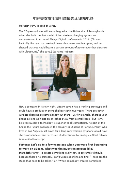
年轻美女发明家打造最强无线充电器Meredith Perry is tired of wires.The 25-year-old was still an undergrad at the University of Pennsylvania when she built the first model of her wireless charging system and demonstrated it at the All Things Digital conference in 2011. (“It was basically like two toaster-sized boxes that were two feet apart, and we showed that you could beam a certain amount of power over that distance with ultrasound,” she says.) Its name? uBeam.Now a company in its own right, uBeam says it has a working prototype and could have a product on store shelves within two years. There are other wireless charging systems already out there—Qi, for example, charges your phone as long as it sits on or inches away from a small base—but Perry believes uBeam’s technology is superior to all competitors. As part of the Shape the Future package in the January 2015 issue of Fortune, Perry, who lives in Los Angeles, sat down for a long conversation by phone about how she created uBeam and her vision of other future technologies. What follows is an edited transcript.Fortun e: Let’s go to a few years ago when you were first beginning to work on uBeam. What was the invention process like?Meredith Perry: To create something really new is extremely difficult, because there’s no protocol. I can’t Google it online and find, “Thes e are the steps that need to be taken,” or, “When somebody created somethingsimilar, these are the questions they asked, these are the people they talked to, and these are the materials they used.” Sometimes you have to create your own materials, your own design, your own manufacturing process. You have to create your own shipping materials that can cover the parts that you built. And we were building all of these tiny little devices by hand. We3-D-printed tools that were useful in creating these devices. For example, we needed a holder that could hold a certain amount of micro beads. So that’s the level of minutiae you have to get involved with in order to actually execute on something that hasn’t been done before.In the beginning I looked at every possible option. I just wanted to solve a problem. And that was: I don’t want to plug in my laptop anymore. I want to be able to move around a room and use all my devices without plugging them in. And I learned that ultrasound was the only type of technology that would work for the experience we are trying to give, which is the Wi-Fi for charging.Then I basically stopped at what materials we needed to make that happen—they’re called transducers, which convert electrical energy into sound and sound back into electricity. I knew that for this project to work, I needed the right transducer, and a transmitter that needs to have this amount of power and be able to beam that power across the room and hit these targets, and so on.And that existed already?Yes, transdu cers are used in speakers. And that’s effectively what uBeam is: a speaker. To make sound, in general you plug in a speaker, which is a bunch of sonic transducers. And we’re using ultrasonic transducers, which is sound above what you can hear. So when you plug in a speaker, you’re taking electricity from a wall, and the electricity is converted into sound, and that sound travels through the air. You’re converting electrical energy into acoustic energy. So that already exists. But a speaker is radiating out sound in 360 degrees, and you’re not going to get that much power from sound unless you focus it. So you have to do the same thing you would do with a laser beam, or with a light bulb—you take the energy and funnel it into a cone. But we’re not physically focusing it, we’re digitally focusing it. So we had to create a transmitter that digitally focuses sound to get enough power out of our ultrasonic speaker across the room. So the whole concept of uBeam worked because I knew that transducers existed. It was just amatter of thinking about sound as a form of energy, which people don’t often think about.Anyway. I’m kind of going into weird details about this.No, it’s fascinating. Let’s talk more about the general process. What was your work method?Well, back in 2012, we had raised a bunch of money, I had this whole plan planned out, but it was extremely difficult because I was working with only contractors. Up until a few months ago, even. Until we raised our Series A [funding round, totaling $10 million and led by Upfront Ventures] we didn’t have any full-time employees except me. So what I did was broke apart the technology into its pieces. I had people working on the transmitter, and there are the electronics behind the transmitter, so I contracted people to create the electronics behind the transmitter. Then I did tons and tons of research to figure out, “What is the most powerful, in-air, ultrasonic transducer I can get?” There are a zillion different types of ultrasonic transducers. Most are made for medical purposes, like sonograms. Then there are people that have designed transducers for cars, like when you back up and you hear the “beep beep.” Then there are transducers you use underwater for sonar, like on a submarine. I needed to figure out which is the best transducer I can use that will beam power through the air. And of course, nothing had been created before that was even close.There was one type of transducer that came out of a university, and it was kind of close, all we had to do was change this, this, and this, and theoretically we should be able to output the power we need using this design… so I contracted the people that wrote those papers to design those transducers. Then I needed someone to design the transmitter transducer, but I also needed someone else to design the receiver transducer, which would capture the energy. So I had individual people working on individual parts of the system.It sounds almost like an assembly line.Right. But it was very difficult because everybody was remote. That was the challenge of the way I set it up. But I could not get anyone to come onfull-time. And I didn’t necessarily need anyone to come on full-time, I just needed each person to finish their one part.The part we couldn’t crack was the transducer. It took us a total of 14 months working on that one particular problem.But that one part is the core engine, isn’t it?Well, for a system to function each part needs to work, but ultimately this piece is the heartbeat, yes.So then it makes sense that the transducer took the longest.Yes, but I didn’t realize just how hard it would be.Had no one ever tried wireless charging before?Wireless charging as a category absolutely has been tried before and is being done by multiple parties using different technologies. But in terms of ultrasonic power, no. Anything that can be beamed through the air can be converted into a usable type of energy. So, people have tried laser for wireless power, but lasers can blind you. And then there’s [Duracell] Powermat, which uses induction and is magnetic, so you stick your phone on a mat and it charges. I don’t consider that true wireless power. Then with magnetic resonance coupling, which a company called WiTricity is using, it’s a totally viable technology but it’s only effe ctive in charging really large objects over really short distances. If you want to charge something that way at a greater distance, you need receivers that are larger than the device you’re charging, so there’s a convenience issue.So at the end of the day, ultrasound is the only technology that is safe, that can travel the distance, that can charge your device, while remaining small and compact. Ultrasonic is the only type of energy that can be commercialized for consumer devices.Well, with one hurdle bei ng that it doesn’t work through walls, like Wi-Fi does.Well, it’s not necessarily a hurdle if you look at the positives. It’s what makes ultrasound the most secure data transmission system in existence.But, pie-in-the-sky hope, you’d want it to work thro ugh walls, right? Oh, of course. But it’s physically impossible. If it were possible, I would take that over the secure data transmission. But even working in one room, think about where that can be applied. Not only within homes and rooms, but think about airports, conference halls, concerts. And you can charge an arbitrary number of devices at any time.You first raised big funding when uBeam was in really early stages. Did you feel a lot of pressure and urgency?There was a sense of insane urgency throughout the entire process. And I pushed and pushed and pushed, but you can only push so hard. I had setmyself an artificial deadline, and I was continuously disappointed that I wasn’t hitting that. But in speaking with people who had created new technologie s before, they would say, “Holy crap, you did that in two years? That’s incredibly short.” In my mind, we were like dinosaurs already, but people who have actually experienced creating new technology before said this was actually pretty fast. But the process killed me. People would check in and ask our progress, but to explain what was actually taking so long would take hours.Was that frustrating?Of course. And the other thing is that throughout the process, I always thought, “Okay, it’s going to work in three months. We’ve got this great new idea to make this transducer function.” So instead of giving someone an update I’d say I’ll tell you in one month. But then we’d fail, and then we’d say we will make a certain change, and then it will work, and that happened about five times. It took about three months to make each change. It was extraordinarily expensive every single time we wanted to make a change to the device. And the lag time was mind-boggling. When you fail five times but you take tiny steps forward each time, it keeps you going. You can stay positive because there’s still light at the end of the tunnel. But at the same time, it really wears you down. You constantly have to think, “Okay, so if this next option doesn’t work, what will we do?” And you just can’t stop until you accomplish your goal. What really kept me going through the entire process was, “Even though this is so hard, it’s still possible.” And I knew that if it was still possible, I had to do it, because it would be so huge. I know that if I was working on something smaller, or something that I didn’t believe could make such an impact on the world then I wouldn’t have been able to keep going through those times.So one of our contractors we brought on, who is is now our CTO, created an entirely new type of transducer during our 14-month marathon of death— it ended up working on the first try. We were running out of money. We had two designs running in parallel, and we knew one of them had to work or we’d be screwed. In the end, both de signs worked, but his was so much cheaper and so much more powerful that we went with his.Take me to the moment when the prototype worked successfully, if there was one big moment.It was when our CTO’s transducer worked. To paint the picture of what life was like at that time: for six and a half months, from December 2013 through June 2014, I was basically living in the tiny garage of my CTO in northern Virginia. It was the worst winter of my entire life, and we spent 10 hours a day just like little Foxconn workers in this garage with no windows, breathing in toxic fumes and trying to get this thing to work over and over and over again.It was either in April or May when we tested out the hybrid, it worked, and I literally screamed for joy. I had the biggest smile on my face because I knew that the future was bright. We knew it was real, it’s going to work, we proved the last piece that we needed to prove.And now we all just wait for it to come out.Yes. Most of the world still doesn’t know about this, whi ch is awesome. So we’re going to release it when we release it, and it’ll be something completely new, and I think that the world will be delighted by the experience.Looking toward the future, what are some of other existing or eventual technologies that excite and interest you?There are a few. And I’ll try to be quick because I get a little too excited. They span between health and transportation and 3-D holograms. So, last year I got really into the idea of creating 3-D, touchable holograms in the air using fog. I wanted to create a system where you could be sitting next to somebody who is in China but could actually touch them, see them, feel them. I built a bunch of hologram machines, which was cool.Is this different from the Tupac hologram at Coachella in 2012? Yeah. This would actually be a three-dimensional display, not just a projection. That’s one thing, the other is I think that people should have some kind of embedded blood sensor that reads your levels continuously. To me, it’s kind of crazy th at only once people feel really crappy, they go to a doctor and find out what’s wrong with them. Why don’t we have some sensor built into the body that lets you know before you feel ill, and ultimately, is connected to an embedded dispensary that can put sugar into your body if your glucose is low? You basically would have an external, but embedded, automatic system that regulates your body.This sound like the first step in making us all half-robot, though…Right! Yes. What I think is crazy is we have so much data and insight into our digital world, but we have no insight into what’s actually going on inside the most important system of all, our bodies. And then, finally, curing cancer is a big one. If it’s not curable, we need to make MRI machines that de tect lumps and growths much smaller than what they can detect right now. Part of the reason we detect cancer at stages where it’s a little too late is that the machines that detect cancer can only see lumps of a certain size. If we were able to detect cancerous growths at a size smaller, we could stop it earlier on. So instead of curing it maybe what we need to do is use machines to catch it much earlier.Many of these ideas you like—wouldn’t they scare most people? Its all very Isaac Asimov.I’ve thought about how to implement this. Speaking for myself, I never want to go to the dentist, I never want to go to the various doctors. So if someone told me to implant something in my body, as a futurist, I’d be down, but as a citizen I would think i t is annoying. And maybe scary. So I think it’s something that needs to be done when you’re super young with the guidance of a pediatrician. We could just get in the habit of, once you’re born, when you’re two years old or something, you get this thing imp lanted and you grow up with it and it becomes part of your life. People are just scared of things that they’re not used to.梅雷迪斯o佩里已经受够了各种充电线。
2019年职称英语理工类A级新增文章篇目(三) Solar Power without Solar Cells太阳能的太阳能电池A dramatic and surprising magnetic effect of light discovered by University of Michigan1 researchers could lead to solar power without traditional semiconductor-based solar cells.戏剧性的和令人惊讶的磁光效应发现michigan1大学研究人员可能导致太阳能没有传统的半导体太阳能电池。
The researchers found a way to make an "optical battery," said Stephen Rand, a professor in the departments of Electrical Engineering and Computer Science, Physics and Applied Physics.研究人员发现了一种使“光电池,说:”史蒂芬兰德,系教授电气工程与计算机科学,物理和应用物理。
Light has electric and magnetic components. Until now, scientists thought the effects of the magnetic field were so weak that they could be ignored. What Rand and his colleagues found is that at the right intensity, when light is traveling through a material that does not conduct electricity, the light field can generate magnetic effects that are 100million times stronger than previously expected. Under these circumstances, the magnetic effects develop strength equivalent to a strong electric effect.光的电场和磁场组成部分。
磁共振无线充电技术:进展与展望目录一、内容概览 (2)1.1 磁共振技术的历史与发展 (2)1.2 无线充电技术的现状与挑战 (3)1.3 磁共振无线充电技术的研究意义 (5)二、磁共振无线充电技术的原理 (6)2.1 磁共振的基本概念 (7)2.2 无线充电的技术原理 (8)2.3 磁共振无线充电系统的组成 (9)三、磁共振无线充电技术的进展 (11)3.1 磁共振无线充电技术的理论研究 (12)3.2 磁共振无线充电技术的实验研究 (13)3.2.1 实验设备与方法 (14)3.2.2 实验结果与分析 (15)3.3 磁共振无线充电技术的应用研究 (16)3.3.1 在医疗领域的应用 (17)3.3.2 在电动汽车领域的应用 (18)3.3.3 在消费电子领域的应用 (20)四、磁共振无线充电技术的展望 (21)4.1 技术发展趋势 (22)4.1.1 提高充电效率 (23)4.1.2 缩小充电距离 (25)4.1.3 降低成本 (26)4.2 应用前景展望 (27)4.2.1 在智能家居中的应用 (28)4.2.2 在工业生产中的应用 (30)4.2.3 在可持续能源领域中的应用 (31)五、结论 (31)5.1 磁共振无线充电技术的发展成果 (32)5.2 对未来研究的建议与展望 (34)一、内容概览磁共振无线充电技术是当前电子领域的一个重要研究内容,本文旨在探讨其进展及未来展望。
本文首先概述磁共振无线充电技术的基本原理和工作机制,阐述其在无线能量传输领域的重要性和应用前景。
接着对磁共振无线充电技术的最新研究进展进行全面的回顾和梳理,包括其技术原理的创新、效率提升等方面取得的突破以及在实际应用中的表现。
然后分析当前磁共振无线充电技术面临的挑战和问题,如成本、技术成熟度、应用场景限制等。
最后展望磁共振无线充电技术的未来发展趋势,包括技术进步、成本降低、应用场景拓展等方面,以及该技术可能带来的社会经济效益和行业变革。
Electromagnetic Induction: The Heart ofModern ElectricityElectromagnetic induction, a fundamental concept in physics, lies at the core of our modern electrical era. It describes the phenomenon where a changing magnetic field creates an electric current in a nearby conductor. This remarkable discovery, first made by Michael Faraday in the 19th century, revolutionized the way we generate, transmit, and utilize electrical energy.The principle of electromagnetic induction is straightforward but profound. Imagine a coil of wire placed near a magnet. When the magnet is moved relative to the coil, the magnetic field around the coil changes, inducing an electric current to flow through the wire. This current can then be harnessed for various applications, such as powering electrical devices or charging batteries.The beauty of electromagnetic induction lies in its versatility and efficiency. It allows us to convert mechanical energy into electrical energy, a process known as electromagnetic generation. This is how most of ourpower plants operate, converting the kinetic energy of moving water, steam, or gas turbines into electricity.Moreover, electromagnetic induction plays a crucialrole in transformers, which are essential for increasing or decreasing the voltage of electrical power. Transformersrely on the principle of electromagnetic induction to transfer electrical energy from one circuit to another without a direct electrical connection. This allows us to safely and efficiently distribute electricity over long distances, powering homes, businesses, and industries worldwide.The applications of electromagnetic induction are vast and diverse. It is the backbone of many modern technologies, including electric motors, generators, induction cooktops, and wireless charging systems. Electric motors, which rely on electromagnetic induction to convert electrical energy into mechanical energy, are ubiquitous in our daily lives, powering vehicles, appliances, and even small toys.The significance of electromagnetic induction extends beyond its practical applications. It has deepened our understanding of the fundamental relationships betweenelectricity and magnetism, laying the foundation for advancements in fields like quantum physics and materials science.In conclusion, electromagnetic induction is a pivotal concept that has revolutionized the way we generate, transmit, and use electrical energy. Its widespread applications and profound impact on modern technology underscore its importance in shaping our world. As we continue to explore and harness the power of electromagnetism, electromagnetic induction remains at the forefront of our efforts, driving innovation and progressin the electrical age.**电磁感应:现代电力的核心**电磁感应,物理学中的一个基本概念,是我们现代电力时代的核心所在。