AD8232_cn数据手册
- 格式:pdf
- 大小:843.42 KB
- 文档页数:28
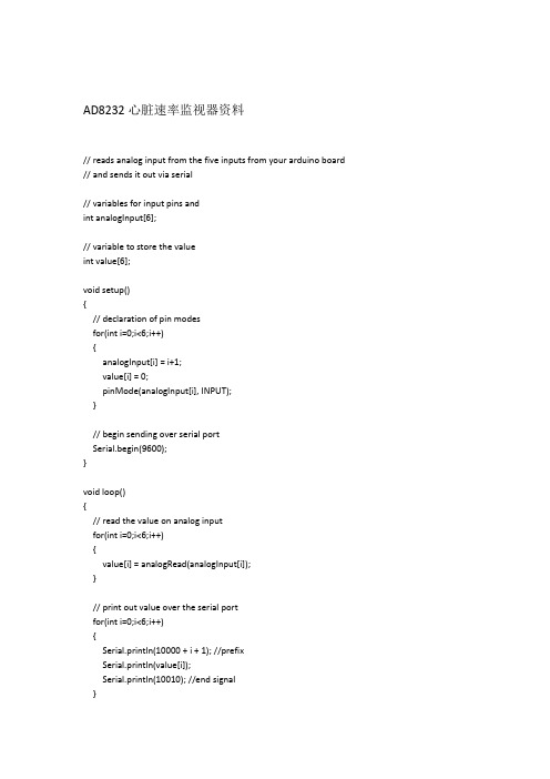
AD8232心脏速率监视器资料// reads analog input from the five inputs from your arduino board // and sends it out via serial// variables for input pins andint analogInput[6];// variable to store the valueint value[6];void setup(){// declaration of pin modesfor(int i=0;i<6;i++){analogInput[i] = i+1;value[i] = 0;pinMode(analogInput[i], INPUT);}// begin sending over serial portSerial.begin(9600);}void loop(){// read the value on analog inputfor(int i=0;i<6;i++){value[i] = analogRead(analogInput[i]);}// print out value over the serial portfor(int i=0;i<6;i++){Serial.println(10000 + i + 1); //prefixSerial.println(value[i]);Serial.println(10010); //end signal}// wait for a bit to not overload the portdelay(10);}GY-MCU90615v1模块资料//////////////////////*GY-MCU90615----MINIVCC----VCCGND----GND1:RX---TX,send A5 51 F6 to GY2632:TX---RX3:MINI_TX---FT232_RX*///////////////////unsigned char Re_buf[11],counter=0;unsigned char sign=0;float TO=0,TA=0;void setup() {Serial.begin(115200);delay(1);Serial.write(0XA5);Serial.write(0X45); //初始化,连续输出模式Serial.write(0XEA); //初始化,连续输出模式}void loop() {unsigned char i=0,sum=0;if(sign){sign=0;for(i=0;i<8;i++)sum+=Re_buf[i];if(sum==Re_buf[i] ) //检查帧头,帧尾{TO=(float)(Re_buf[4]<<8|Re_buf[5])/100;Serial.print("TO:");Serial.println(TO);TA=(float)(Re_buf[6]<<8|Re_buf[7])/100;Serial.print("TA:");Serial.println(TA);}}}void serialEvent() {while (Serial.available()) {Re_buf[counter]=(unsigned char)Serial.read();if(counter==0&&Re_buf[0]!=0x5A) return; // 检查帧头counter++;if(counter==9) //接收到数据{counter=0; //重新赋值,准备下一帧数据的接收sign=1;}}}MAX30100芯片心率血氧传感器模块心率传感器模块心率模块/*Arduino-MAX30100 oximetry / heart rate integrated sensor libraryCopyright (C) 2016 OXullo Intersecans <x@>This program is free software: you can redistribute it and/or modifyit under the terms of the GNU General Public License as published bythe Free Software Foundation, either version 3 of the License, or(at your option) any later version.This program is distributed in the hope that it will be useful,but WITHOUT ANY WARRANTY; without even the implied warranty of MERCHANTABILITY or FITNESS FOR A PARTICULAR PURPOSE. See theGNU General Public License for more details.You should have received a copy of the GNU General Public Licensealong with this program. If not, see </licenses/>.*/#include <Wire.h>#include "MAX30100_PulseOximeter.h"#define REPORTING_PERIOD_MS 1000// PulseOximeter is the higher level interface to the sensor// it offers:// * beat detection reporting// * heart rate calculation// * SpO2 (oxidation level) calculationPulseOximeter pox;uint32_t tsLastReport = 0;// Callback (registered below) fired when a pulse is detectedvoid onBeatDetected(){Serial.println("Beat!");}void setup(){Serial.begin(115200);Serial.print("Initializing pulse oximeter..");// Initialize the PulseOximeter instance// Failures are generally due to an improper I2C wiring, missing power supply// or wrong target chipif (!pox.begin()) {Serial.println("FAILED");for(;;);} else {Serial.println("SUCCESS");}// The default current for the IR LED is 50mA and it could be changed// by uncommenting the following line. Check MAX30100_Registers.h for all the // available options.// pox.setIRLedCurrent(MAX30100_LED_CURR_7_6MA);// Register a callback for the beat detectionpox.setOnBeatDetectedCallback(onBeatDetected);}void loop(){// Make sure to call update as fast as possible// Asynchronously dump heart rate and oxidation levels to the serial// For both, a value of 0 means "invalid"if (millis() - tsLastReport > REPORTING_PERIOD_MS) {Serial.print("Heart rate:");Serial.print(pox.getHeartRate());Serial.print("bpm / SpO2:");Serial.print(pox.getSpO2());Serial.println("%");tsLastReport = millis();}}。

AD8232 中文产品数据手册AD8232 中文产品数据手册1、引言1.1 产品介绍AD8232 是一款测量心电图信号的集成电路。
它可以通过电极传感器接收和放大心电图信号,并输出一个幅度稳定的电压信号。
本文档提供了 AD8232 的详细技术规格和功能介绍。
2、技术规格2.1 电气特性2.1.1 工作电压范围AD8232 的工作电压范围为3.3V至5V。
2.1.2 输入电压范围AD8232 的输入电压范围为-0.3V至3.3V。
2.1.3 工作温度范围AD8232 的工作温度范围为-40°C至85°C。
2.2 功能介绍2.2.1 心电图信号放大AD8232 可以将心电图信号放大至适合读取的幅度,并具备一定的抗干扰能力。
2.2.2 低功耗设计AD8232 采用了低功耗设计,可以在电池供电下长时间工作。
2.2.3 SPI接口AD8232 提供了SPI接口,方便与微控制器或其他外部设备进行通信和控制。
3、应用示例3.1 心率监测AD8232 可以用于实时监测和记录患者的心率,并输出可读取的心电图信号。
3.2 健身追踪AD8232 可以用于追踪用户的心率和运动状况,进行健康管理和运动监测。
4、附件本文档附带的附件包括 AD8232 的封装图纸和电路设计示例。
5、法律名词及注释5.1 FDAFDA是美国食品药品监督管理局(Food and Drug Administration)的缩写,负责监管食品、药品和医疗器械的安全性和有效性。
5.2 CE认证CE认证是欧洲联盟对电子产品的一种安全认证,表示该产品符合相关的欧洲安全标准。
6、结束语本文档提供了 AD8232 中文产品数据手册的详细内容和功能介绍。
通过阅读本文档,用户可以了解该产品的技术规格和应用示例。
如需更多信息,请参考附件部分的封装图纸和电路设计示例。
关于ADI混合信号处理技术产品解决方案
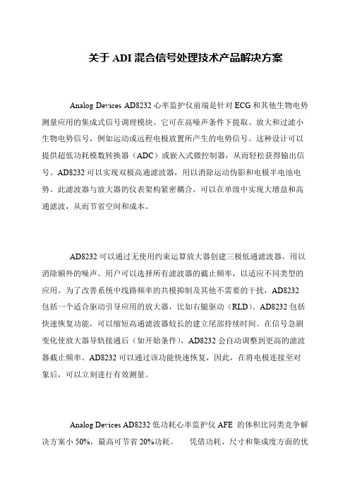
Analog Devices AD8232心率监护仪前端是针对ECG和其他生物电势测量应用的集成式信号调理模块。
它可在高噪声条件下提取、放大和过滤小生物电势信号,例如运动或远程电极放置所产生的电势信号。
这种设计可以提供超低功耗模数转换器(ADC)或嵌入式微控制器,从而轻松获得输出信号。
AD8232可以实现双极高通滤波器,用以消除运动伪影和电极半电池电势。
此滤波器与放大器的仪表架构紧密耦合,可以在单级中实现大增益和高通滤波,从而节省空间和成本。
AD8232可以通过无使用约束运算放大器创建三极低通滤波器,用以消除额外的噪声。
用户可以选择所有滤波器的截止频率,以适应不同类型的应用。
为了改善系统中线路频率的共模抑制及其他不需要的干扰,AD8232
包括一个适合驱动引导应用的放大器,比如右腿驱动(RLD)。
AD8232包括快速恢复功能,可以缩短高通滤波器较长的建立尾部持续时间。
在信号急剧变化使放大器导轨接通后(如开始条件),AD8232会自动调整到更高的滤波器截止频率。
AD8232可以通过该功能快速恢复,因此,在将电极连接至对象后,可以立刻进行有效测量。
Analog Devices AD8232低功耗心率监护仪AFE 的体积比同类竞争解决方案小50%,最高可节省20%功耗。
凭借功耗、尺寸和集成度方面的优。

电路笔记CN-0382Circuits from the Lab® reference designs are engineered and tested for quick and easy system integration to help solve today’s analog, mixed-signal, and RF design challenges. For more information and/or support, visit /CN0382.连接/参考器件AD7124-4 集成PGA和基准电压源的低功耗24位Σ-Δ型ADCAD5421 16位、环路供电、4 mA至20 mA DAC AD5700 低功耗HART调制解调器SPI隔离器ADuM1441ADP162超低静态电流、150 mA CMOS线性稳压器ADG5433高压防闩锁型三通道SPDT开关Rev. 0Circuits from the Lab® reference designs from Analog Devices have been designed and built by Analog Devices engineers. Standard engineering practices have been employed in the design and construction of each circuit, and their function and performance have been tested and veri ed in a labenvironment at room temperature. However, you are solely responsible for testing the circuit and determining its suitability and applicability for your use and application. Accordingly, in no event shall Analog Devices be liable for direct, indirect, special, incidental, consequential or punitive damages due to any cause whatsoever connected to the use of any Circ uits from the Lab circuits. (Continued on last page) One Technology Way, P.O. Box 9106, Norwood, MA 02062-9106, U.S.A. Tel: 781.329.4700 Fax: 781.461.3113 ©2015 Analog Devices, Inc. All rights reserved.采用低功耗、精密、24位Σ-Δ型ADC的隔离式4 mA至20 mA/HART工业温度和压力变送器评估和设计支持电路评估板DEM O-AD7124-DZ评估板设计和集成文件原理图、布局文件、物料清单、代码示例电路功能与优势图1所示电路是一种隔离式智能工业现场仪表,可与许多类型的模拟传感器,如温度传感器(Pt100、Pt1000、热电偶)或桥式压力传感器等接口。
________________General DescriptionThe MAX823/MAX824/MAX825* microprocessor (µP)supervisory circuits combine reset output, watchdog,and manual reset input functions in 5-pin SOT23 and SC70 packages. They significantly improve system relia-bility and accuracy compared to separate ICs or discrete components. The MAX823/MAX824/MAX825 are specifi-cally designed to ignore fast transients on V CC .Seven preprogrammed reset threshold voltages are available (see Reset Threshold Table ). All three devices have an active-low reset output, which is guaranteed to be in the correct state for V CC down to 1V. The MAX823also offers a watchdog input and manual reset input.The MAX824 offers a watchdog input and a comple-mentary active-high reset. The MAX825 offers a manual reset input and a complementary active-high reset. The S elector Guide explains the functions offered in this series of parts.________________________ApplicationsComputers and ControllersEmbedded Controllers Intelligent Instruments Automotive Systems Critical µP MonitoringPortable/Battery-Powered EquipmentFeatureso Precision Monitoring of +2.5V, +3V, +3.3V, and +5V Power Supplieso Operating Current:6µA (MAX823L/M) (SC70)2µA (MAX825T/S/R/Z/Y) (SC70)o Fully Specified Over Temperature o 140ms min Power-On Reseto Guaranteed RESET Valid to V CC = 1V o Power-Supply Transient Immunity o Watchdog Timer with 1.6s Timeout (MAX823/MAX824)o Manual Reset Input (MAX823/MAX825)o No External ComponentsMAX823/MAX824/MAX8255-Pin Microprocessor Supervisory Circuits WithWatchdog Timer and Manual Reset________________________________________________________________Maxim Integrated Products 1______________________Selector Guide19-0487; Rev 4; 7/01†Insert the desired suffix letter (from the Reset Threshold table) into the blank to complete the part number. All devices are available in tape-and-reel only. There is a 2500 piece minimum order increment.Typical Operating Circuit appears at end of data sheet.Marking Information appears at end of data sheet.Ordering InformationOrdering Information continued at end of data sheet.Reset Threshold TablePin Configurations*Patents PendingFor pricing, delivery, and ordering information,please contact Maxim/Dallas Direct!at 1-888-629-4642, or visit Maxim’s website at .M A X 823/M A X 824/M A X 8255-Pin Microprocessor Supervisory Circuits With Watchdog Timer and Manual Reset 2_______________________________________________________________________________________ABSOLUTE MAXIMUM RATINGSELECTRICAL CHARACTERISTICS(V CC = +4.75V to +5.5V for MAX82_L, V CC = +4.5V to +5.5V for MAX82_M, V CC = +3.15V to +3.6V for MAX82_T, V CC = +3V to +3.6V for MAX82_S, V CC = +2.7V to +3.6V for MAX82_R, V CC = +2.38V to +2.75V for MAX82_Z, V CC = +2.25V to +2.75V for MAX82_Y, T A = T MIN to T MAX , T A = -40°C to +85°C (SC70), T A = -40°C to +125°C (SOT23), unless otherwise noted. Typical values are at T A = +25°C.) (Note 1)Stresses beyond those listed under “Absolute Maximum Ratings” may cause permanent damage to the device. These are stress ratings only, and functional operation of the device at these or any other conditions beyond those indicated in the operational sections of the specifications is not implied. Exposure to absolute maximum rating conditions for extended periods may affect device reliability.V CC ........................................................................-0.3V to +6.0V All Other Pins..............................................-0.3V to (V CC + 0.3V)Input Current, All Pins Except RESET and RESET ..............20mA Output Current, RESET, RESET ..........................................20mA Continuous Power Dissipation (T A = +70°C)5-Pin SC70 (derate 3.1mW/°C above +70°C)...............247mW5-Pin SOT23 (derate 7.1mW/°C above +70°C).............571mW Operating Temperature RangeMAX82_EXK......................................................-40°C to +85°C MAX82_EUK...................................................-40°C to +125°C Storage Temperature Range.............................-65°C to +150°C Lead Temperature (soldering, 10s).................................+300°CMAX823/MAX824/MAX8255-Pin Microprocessor Supervisory Circuits WithWatchdog Timer and Manual Reset_______________________________________________________________________________________3ELECTRICAL CHARACTERISTICS (continued)(V CC = +4.75V to +5.5V for MAX82_L, V CC = +4.5V to +5.5V for MAX82_M, V CC = +3.15V to +3.6V for MAX82_T, V CC = +3V to +3.6V for MAX82_S, V CC = +2.7V to +3.6V for MAX82_R, V CC = +2.38V to +2.75V for MAX82_Z, V CC = +2.25V to +2.75V for MAX82_Y, T = T to T , T = -40°C to +85°C (SC70), T = -40°C to +125°C (SOT23), unless otherwise noted. Typical valuesM A X 823/M A X 824/M A X 8255-Pin Microprocessor Supervisory Circuits With Watchdog Timer and Manual Reset 4_______________________________________________________________________________________Note 2:The RESET short-circuit current is the maximum pullup current when RESET is driven low by a µP bidirectional reset pin.Note 3:WDI is internally serviced within the watchdog period if WDI is left unconnected.Note 4:The WDI input current is specified as the average input current when the WDI input is driven high or low. The WDI input is designed to drive a three-stated output device with a 10µA maximum leakage current and a maximum capacitive load of 200pF. This output device must be able to source and sink at least 200µA when active.ELECTRICAL CHARACTERISTICS (continued)(V CC = +4.75V to +5.5V for MAX82_L, V CC = +4.5V to +5.5V for MAX82_M, V CC = +3.15V to +3.6V for MAX82_T, V CC = +3V to +3.6V for MAX82_S, V CC = +2.7V to +3.6V for MAX82_R, V CC = +2.38V to +2.75V for MAX82_Z, V CC = +2.25V to +2.75V for MAX82_Y, T A = T MIN to T MAX , T A = -40°C to +85°C (SC70), T A = -40°C to +125°C (SOT23), unless otherwise noted. Typical values are at T A = +25°C.) (Note 1)MAX823/MAX824/MAX8255-Pin Microprocessor Supervisory Circuits WithWatchdog Timer and Manual Reset_______________________________________________________________________________________5__________________________________________Typical Operating CharacteristicsMAX823_, V CC = +5V, T A = +25°C, unless otherwise noted.)132654879-402040-206080100120TEMPERATURE (°C)S U P P L Y C U R R E N T (µA )V CC SUPPLY CURRENT vs. TEMPERATURE250150-40-2040100RESET TIMEOUT PERIOD vs. TEMPERATURE170160180230240M A X 823/4/5 t o c 02TEMPERATURE (°C)R E S E T T I M E O U T P E R I O D (m s )20806021022019020030-40-2040100RESET COMPARATOR PROPAGATION DELAYvs. TEMPERATURE525TEMPERATURE (°C)P R O P A G A T I O N D E L A Y (µs )02080602010152.01.0-40-2040100WATCHDOG TIMEOUT PERIODvs. TEMPERATURE1.21.11.31.81.9M A X 823/4/5 t o c 04TEMPERATURE (°C)W A T C H D O G T I M E O U T P E R I O D (s )2080601.61.71.41.5 1.060.940.960.981.001.021.04-40-2040100NORMALIZED RESET THRESHOLD VOLTAGE vs. TEMPERATUREM A X 823/4/5 t o c 05TEMPERATURE (°C)N O R M A L I Z E D R E S E T T H R E S H O L D (V )0208060105201530253545405040608020100120140180160200RESET THRESHOLD OVERDRIVE (mV), V RST - V CCT R A N S I E N T D U R A T I O N (µs )MAXIMUM V CC TRANSIENT DURATION vs. RESET THRESHOLD OVERDRIVEM A X 823/M A X 824/M A X 8255-Pin Microprocessor Supervisory Circuits With Watchdog Timer and Manual Reset 6_______________________________________________________________________________________Pin DescriptionFigure 1. Functional DiagramMAX823/MAX824/MAX8255-Pin Microprocessor Supervisory Circuits WithWatchdog Timer and Manual Reset_______________________________________________________________________________________7_______________Detailed DescriptionRESET OutputA microprocessor ’s (µP ’s) reset input starts the µP in a known state. The MAX823/MAX824/MAX825 µP super-visory circuits assert a reset to prevent code-execution errors during power-up, power-down, and brownout conditions. RESET is guaranteed to be a logic low for V CC down to 1V. Once V CC exceeds the reset thresh-old, an internal timer keeps RESET low for the specified reset timeout period (t RP ); after this interval, RESET returns high (Figure 2).If a brownout condition occurs (V CC dips below the reset threshold), RESET goes low. Each time RESET is asserted it stays low for the reset timeout period. Any time V CC goes below the reset threshold the internal timer restarts. RESET both sources and sinks current.RESET on the MAX824/MAX825 is the inverse of RESET .Manual Reset Input (MAX823/MAX825)Many µP-based products require manual reset capabili-ty, allowing the operator, a test technician, or external logic circuitry to initiate a reset. On the MAX823/MAX825, a logic low on MR asserts reset. Reset remains asserted while MR is low, and for t RP (200ms nominal)after it returns high. MR has an internal 52k Ωpullup resistor, so it can be left open if not used. This input can be driven with CMOS logic levels or with open-drain/collector outputs. Connect a normally open momentary switch from MR to GND to create a manual-reset func-tion; external debounce circuitry is not required. If MR is driven from long cables or the device is used in a noisy environment, connect a 0.1µF capacitor from MR to GND to provide additional noise immunity.Watchdog Input (MAX823/MAX824)In the MAX823/MAX824, the watchdog circuit monitors the µP ’s activity. If the µP does not toggle the watchdog input (WDI) within t WD (1.6s), reset asserts. The internal 1.6s timer is cleared by either a reset pulse or by tog-gling WDI, which detects pulses as short as 50ns.While reset is asserted, the timer remains cleared and does not count. As soon as reset is released, the timer starts counting (Figure 3).Disable the watchdog function by leaving WDI uncon-nected or by three-stating the driver connected to WDI.The watchdog input is internally driven low during the first 7/8 of the watchdog timeout period and high for the last 1/8 of the watchdog timeout period. When WDI is left unconnected, this internal driver clears the 1.6s timer every 1.4s. When WDI is three-stated or uncon-nected, the maximum allowable leakage current is 10µA and the maximum allowable load capacitance is 200pF.Applications InformationWatchdog Input CurrentThe MAX823/MAX824 WDI inputs are internally driven through a buffer and series resistor from the watchdog counter (Figure 1). When WDI is left unconnected, the watchdog timer is serviced within the watchdog timeout period by a low-high-low pulse from the counter chain.For minimum watchdog input current (minimum overall power consumption), leave WDI low for the majority of the watchdog timeout period, pulsing it low-high-low once within the first 7/8 of the watchdog timeout period to reset the watchdog timer. If WDI is externally driven high for the majority of the timeout period, up to 160µA can flow into WDI.Figure 2. Reset Timing Diagram Figure 3. MAX823/MAX824 Watchdog Timing RelationshipM A X 823/M A X 824/M A X 8255-Pin Microprocessor Supervisory Circuits With Watchdog Timer and Manual Reset 8_______________________________________________________________________________________Interfacing to µPs with Bidirectional Reset PinsThe RESET output maximum pullup current is 800µA for L/M versions (400µA for T/S/R/Z/Y versions). This allows µPs with bidirectional resets, such as the 68H C11, to force RESET low when the MAX823/MAX824/MAX825are pulling RESET high (Figure 4).Negative-Going V CC TransientsThese supervisors are relatively immune to short-duration, negative-going V CC transients (glitches), which usually do not require the entire system to shut down.Resets are issued to the µP during power-up, power-down, and brownout conditions.The Typical Operating Characteristics show a graph of the MAX823_’s Maximum V CC Transient Duration vs.Reset Threshold Overdrive, for which reset pulses are not generated. The graph was produced using nega-tive-going V CC pulses, starting at 5V and ending below the reset threshold by the magnitude indicated (reset threshold overdrive). The graph shows the maximum pulse width that a negative-going V CC transient can typically have without triggering a reset pulse. As the amplitude of the transient increases (i.e., goes farther below the reset threshold), the maximum allowable pulse width decreases.An optional 0.1µF bypass capacitor mounted close to V CC provides additional transient immunity.Watchdog Software Considerations(MAX823/MAX824)One way to help the watchdog timer monitor software execution more closely is to set and reset the watchdog input at different points in the program, rather than pulsing the watchdog input high-low-high or low-high-low. This technique avoids a stuck loop, in which the watchdog timer would continue to be reset inside the loop, keeping the watchdog from timing out.Figure 5 shows an example of a flow diagram where the I/O driving the watchdog input is set high at the begin-ning of the program, set low at the beginning of every subroutine or loop, then set high again when the pro-gram returns to the beginning. If the program should hang in any subroutine, the problem would quickly be corrected, since the I/O is continually set low and the watchdog timer is allowed to time out, causing a reset or interrupt to be issued. As described in the Watchdog Input Current section, this scheme results in higher time average WDI input current than does leaving WDI low for the majority of the timeout period and periodically pulsing it low-high-low.Figure 4. Interfacing to µPs with Bidirectional Resets Figure 5. Watchdog Flow DiagramMAX823/MAX824/MAX8255-Pin Microprocessor Supervisory Circuits WithWatchdog Timer and Manual Reset9Typical Operating Circuit____________________Chip InformationTRANSISTOR COUNT: 607PROCESS TECHNOLOGY: BiCMOSOrdering Information (continued)†Insert the desired suffix letter (from the Reset Threshold table) intothe blank to complete the part number. All devices are available in tape-and-reel only. There is a 2,500 piece minimum order increment.Marking InformationM A X 823/M A X 824/M A X 8255-Pin Microprocessor Supervisory Circuits With Watchdog Timer and Manual ResetMaxim cannot assume responsibility for use of any circuitry other than circuitry entirely embodied in a Maxim product. No circuit patent licenses are implied. Maxim reserves the right to change the circuitry and specifications without notice at any time.10__________________Maxim Integrated Products, 120 San Gabriel Drive, Sunnyvale, CA 94086 (408) 737-7600©2001 Maxim Integrated ProductsPrinted USAis a registered trademark of Maxim Integrated Products.Package Information。