伟速达表面处理资料
- 格式:xls
- 大小:500.50 KB
- 文档页数:4
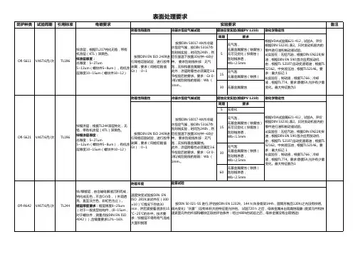
表面处理的代码及应用范围网络能源有限公司修订信息表目录目录 (3)前言 (4)表面处理代码 (5)1目的 (5)2适用范围 (5)3关键词 (5)4弓丨用/参考标准或资料 (5)5规范内容 (5)5.1术语 (5)5.2技术说明 (6)5.3备注 (6)表面处理工艺的应用范围 (12)1目的 (12)2适用范围 (12)3关键词 (12)4引用/参考标准或资料 (12)5规范内容 (12)5.1术语 (12)5.2技术内容 (12)、八, 、■刖言本规范由艾默生网络能源有限公司研发部发布实施,适用于本公司的产品设计开发及相关活动。
本规范由结构造型设计中心、SQE部门遵照执行。
本规范拟制部门:结构造型设计中心本规范拟制人:何浩本规范审核人:张士杰徐建平李立华本规范批准人:张运清、 表面处理代码1目的本规范规定了图纸中标注表面处理时所用的代码内容,并说明了每种工艺所对应的技 术要求以及每种外观要求应采用的标准样板。
适用范围本规范适用于艾默生网络能源有限公司产品的结构件零件和组合件的设计及图纸标注。
关键词表面处理电镀喷漆粉末喷涂标准代码引用/参考标准或资料下列标准包含的条文,通过在本标准中引用而构成本标准的条文。
在标准出版时,所 示版本均为有效。
所有标准都会被修订,使用本标准的各方应探讨使用下列标准最新版本 的可能性。
铝合金表面处理技术规范 结构件电镀技术规范金属零组件喷漆喷粉磷化技术规范 标准样板的规定及清单5规范内容TS-S180003001 TS-S180003002 TS-S180003003 TS-S1800030055.1 术语5.1.1 5.1.2 5.1.3 5.1.4 5.1.5 5.1.6 5.1.7 5.1.8 5.1.9 组合件:指用铆接、 无色阳极化:即无色硫酸阳极化(纯水封闭)。
光亮阳极化:即化学抛光后再进行无色硫酸阳极化处理。
喷砂光亮阳极化:即先喷砂再进行光亮阳极化处理。
佛山市硅博士新材料有限公司 1产品技术资料SDDZ01002013年5月20日产品简介硅博士SDDZ0100是一款单组纳米耐高温绝缘漆,易操作,能快速空气固化喷涂,具有优良的电性能和对各种电路板有良好的附着力,有良好的耐高低温性能;固化后成一层透明保护膜,漆膜具有优越的绝缘、耐温、防潮、防漏电、防震、防尘、防腐蚀、防盐雾、防霉、防老化、耐电晕等性能。
短时间最高耐温可以达到200℃。
典型用途该耐高温绝缘漆主要应用于热带电工产品,继电器、LED 线路板、航海仪器仪表控制板、热工仪表、精密仪器、载波通讯控制板,安防电子线路板,车载主板,电脑主板,灯饰灯具线路板,LED 电子控制板、变频器控制板,电源板的电子元器的防护及电机防护等方面。
1、电子电器方面:应用于继电器的弹性零件、镀锌、镀隔件、粉末冶金件、变压器线圈、印制电路板和整机防护,以及电话交换机用继电器铁芯防腐及正机防护。
大型电子记时记分仪上印制电路板的防护,MOS 电路,微带型二极管的防潮。
机床电器上控制变压器,照明变压器的浸渍处理。
力矩电机的铁芯涂复,及用于ZDN —500型平陡两用弧焊机的印制电路板防潮,用于电视机显象管的绝缘防潮。
2、无线电通讯方面:用于超短波电台的印制电路板,中波广播发射机,短波 报 话 机上的高频回路线圈,高频瓷件、胶木件等元件浸渍防潮处理。
960路和1800路载波机高频电感线圈,滤波器线圈,信号变压器,机盘磁心体及其元件防霉。
固化前特性典型值 范围外观 无色透明 基料化学成份 丙烯酸树脂粘度 (cp ) 200 150~250密度(g/cm 3) 1.0 0.95~1.05(GB/T 13354-1992)固化后特性常温固化适宜涂层厚度(µm) 0.01~0.1 (加热固化: 30min/ 180°) 表干时间:1h 完全固化时间:7天 使用温度范围:-40~180℃ 固化厚硬度:5H 电气性能:介电强度(KV/mm )60 体积电阻率(Ohm-cm) 3.3X10¹⁶抗拉强度(MPa ): ≥4操作工艺说明:三防漆涂覆作业温度应在15℃-30℃之间,相对湿度不行高于85%的条件下进行,线路板作为复合材料,易受潮。
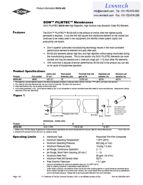
Product Information BW30-400Page 1 of 2 ™® Trademark of The Dow Chemical Company (“Dow”) or an affiliated company of DowForm No. 609-00091-0910DOW™ FILMTEC™ MembranesDOW FILMTEC BW30-400 High Rejection, High Surface Area Brackish Water RO ElementFeaturesThe DOW™ FILMTEC™ BW30-400 is the product of choice when the highest qualitypermeate is required. It was the first 400 square foot membrane element on the market and continues to be widely used in new equipment and retrofits where system capital and productivity are factors.• Dow’s superior automated manufacturing technology results in the most consistent performance element-to-element and year-after-year.• BW30-400 elements deliver high flow and high rejection without being chlorinated during the manufacturing process. This is one reason why DOW FILMTEC elements are more durable and may be cleaned over a wider pH range (pH 1-13) than other RO elements. • With more than a decade of proven performance, BW30-400 is the product you can rely on for years of trouble-free operation.Product SpecificationsProductPart number Active area ft 2 (m 2) Feed spacer thickness (mil) Permeate flow rate gpd (m 3/d) Stabilized salt rejection (%) Minimum salt rejection (%) BW30-40098650400 (37)2810,500 (40)99.5%99.0%1. Permeate flow and salt rejection based on the following standard conditions: 2,000 ppm NaCl, 225 psi (15.5 bar), 77°F (25°C), pH 8 and 15% recovery.2. Flow rates for individual elements may vary but will be no more than 15% below the value shown.3. Sales specifications may vary as design revisions take place.4. Active area guaranteed +/-3%. Active area as stated by Dow is not comparable to nominal membrane area often stated by some manufacturers. Measurement method described in Form No. 609-00434.Figure 1Dimensions – inches (mm) Product A BC BW30-40040.0 (1,016)1.125 ID (29)7.9 (201)1. Refer to Dow FilmTec Design Guidelines for multiple-element applications and recommended element recovery rates for various feed sources. 1 inch = 25.4 mm2. Element to fit nominal 8.0-inch (203 mm) I.D. pressure vessel.• • • • • • • • •Membrane Type Polyamide Thin-Film Composite Maximum Operating Temperature a 113°F (45°C) Maximum Operating Pressure 600 psig (41 bar) Maximum Pressure Drop 15 psig (1.0 bar)pH Range, Continuous Operation a2 - 11 pH Range, Short-Term Cleaning (30 min.)b1 - 13 Maximum Feed Flow 85 gpm (19 m 3/hr) Maximum Feed Silt Density Index SDI 5Free Chlorine Tolerance c< 0.1 ppm a Maximum temperature for continuous operation above pH 10 is 95°F (35°C).b Refer to Cleaning Guidelines in specification sheet 609-23010.cUnder certain conditions, the presence of free chlorine and other oxidizing agents will cause premature membrane failure. Since oxidation damage is not covered under warranty, Dow recommends removing residual free chlorine by pretreatment prior to membrane exposure. Please refer to technical bulletin 609-22010 for more information.Operating LimitsL enntech***************** Tel. +31-152-610-900 Fax. +31-152-616-289Page 2 of 2™®Trademark of The Dow Chemical Company ("Dow") or an affiliated company of Dow Form No. 609-00091-0910Important InformationProper start-up of reverse osmosis water treatment systems is essential to prepare the membranes for operating service and to prevent membrane damage due to overfeeding or hydraulic shock. Following the proper start-up sequence also helps ensure that system operating parameters conform to design specifications so that system water quality and productivity goals can be achieved.Before initiating system start-up procedures, membrane pretreatment, loading of themembrane elements, instrument calibration and other system checks should be completed.Please refer to the application information literature entitled “Start-Up Sequence” (Form No. 609-02077) for more information.Operation GuidelinesAvoid any abrupt pressure or cross-flow variations on the spiral elements during start-up, shutdown, cleaning or other sequences to prevent possible membrane damage. During start-up, a gradual change from a standstill to operating state is recommended as follows: • • Feed pressure should be increased gradually over a 30-60 second time frame.Cross-flow velocity at set operating point should be achieved gradually over 15-20 seconds. • • • • • • • Permeate obtained from first hour of operation should be discarded.GeneralInformationKeep elements moist at all times after initial wetting.If operating limits and guidelines given in this bulletin are not strictly followed, the DOW™ FILMTEC™ Reverse Osmosis and Nanofiltration Three-Year Prorated Limited Warranty (Form No. 609-35010) will be null and void.To prevent biological growth during prolonged system shutdowns, it is recommended that membrane elements be immersed in a preservative solution.The customer is fully responsible for the effects of incompatible chemicals and lubricants on elements.Maximum pressure drop across an entire pressure vessel (housing) is 50 psi (3.4 bar). Avoid static permeate-side backpressure at all times.Regulatory NoteThese membranes may be subject to drinking water application restrictions in somecountries: please check the application status before use and sale.Notice: The use of this product in and of itself does not necessarily guarantee the removal of cysts and pathogens from water. Effective cyst and pathogen reduction is dependent on the complete system design and on the operation and maintenance of the system. Notice: No freedom from any patent owned by Dow or others is to be inferred. Because use conditions and applicable laws may differ from one location to another and may change with time, Customer is responsible for determining whether products and the information in this document are appropriate for Customer's use and for ensuring that Customer's workplace and disposal practices are in compliance with applicable laws and other government enactments. The product shown in this literature may not be available for sale and/or available in all geographies where Dow is represented. The claims made may not have been approved for use in all countries. Dow assumes no obligation or liability for the information in this document. References to "Dow" or the "Company" mean the Dow legal entity selling the products to Customer unless otherwise expressly noted. NO WARRANTIES ARE GIVEN; ALL IMPLIED WARRANTIES OF MERCHANTABILITY OR FITNESS FOR A PARTICULAR PURPOSE ARE EXPRESSLY EXCLUDED.L enntech***************** Tel. + Fax. +31-152-616-289。
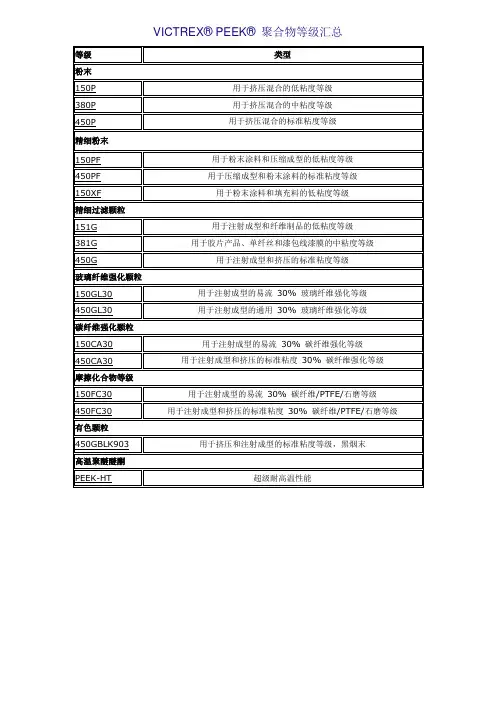
VICTREX® PEEK® 聚合物等级汇总粉末Victrex® PEEK® 150P、380P 和450P 的性能精细粉末Victrex® PEEK® 150PF、450PF 和150XF 的性能精细过滤颗粒摩擦化合物等级Victrex® PEEK® 150FC30 和450FC30 性能有色颗粒高温聚醚醚酮加工简介PEEK的加工方法有:挤出成型、注塑成型、喷涂成型、压缩成型。
挤出:熔胶筒温度柱状加热器必须达到400°C 并且保持温度在± 2°C 内变动。
因此,不能使用铸铝加热器,而应使用高温合金或陶瓷加热器代替。
柱状加热器应触及全部金属表面以确保形成均匀的温度分布。
不能直接加热的区域应使用高温绝热法来以避免形成“冷点”。
注塑:射出成型機為PEEK® 聚合物材料準備的建議開始溫度喷涂:静电喷涂和流态层喷涂静电喷涂和流态层喷涂都是传送固体PEEK® 聚合物粉末到金属基体的加热表面的方法。
一旦精细粉末与金属接触,颗粒与表面粘合并逐渐形成牢固的表层。
静电喷涂技术通常使用空气传送精细粉末到达静电喷涂枪的喷嘴处。
在喷嘴和基体之间具有大的势差,该势差用于为精细粉末的喷射导向。
流态层技术使用压缩空气使一定质量的粉末材料在确定的空间中传播。
受控的粉末云雾在加热的基体上方形成。
加工简介注射成型机械设计模具设计操作条件注射压力和螺杆速度故障解决挤压机械设计熔胶筒温度电动机熔胶筒容量和停留时间螺杆设计熔化过滤导线和电缆涂层铸膜和铸片压缩成型粉末喷涂静电喷涂和流态层喷涂等离子喷涂精加工操作机械加工退火概述粘合剂粘接焊接法真空镀膜PEEK 聚合物材料着色加工准备和处理PEEK® 聚合物装载在承重纸箱或扁平状箱子内的密封聚乙烯袋子中。
极力建议在以后的运输和存储过程中,该材料要密封在原包装中。
机械加工常见的表面处理种类和作用公司标准化编码 [QQX96QT-XQQB89Q8-NQQJ6Q8-MQM9N]机械加工常见表面处理的种类基本原理和用途表面处理工艺:静电喷涂?、烤漆?、镀锌、镀铬、镀镍、镀钛、镀金、镀银、铝阳极?、浸渗、喷油、喷砂、DLC处理、铁氟龙处理、染黑、冷电镀静电喷涂:静电喷涂是利用高压静电电场使带负电的微粒沿着电场相反的方向定向运动,并将涂料微粒吸附在的一种喷涂方法。
由喷枪、喷杯以及静电喷涂等组成。
静电喷涂的作用1、一次涂装可以得到较厚的涂层,例如涂覆100~300μm的涂层,用一般普通的溶剂涂料,约需涂覆4~6次,而用粉末涂料则一次就可以达到该厚度。
涂层的耐腐性能很好。
2、粉末涂料不含溶剂,无三废公害,改善了劳动卫生条件。
3、采用粉末静电喷涂等新工艺,效率高,适用于自动流水线涂装,粉末利用率高,可回收使用。
4、除热固性的环氧、聚酯、丙烯酸外,尚有大量的热塑性耐脂可作为粉末涂料,如聚乙烯、聚丙烯、聚苯乙烯、氟化聚醚、尼龙、聚碳酸脂以及各类含氟树脂等。
粉末涂料开始用于防护和电气缘方面,随着科技的发展,目前已广泛使用于汽车工业、电气绝缘、耐腐蚀化学泵、阀门、汽缸、管道、屋外钢制构件、钢制家具、铸件等表面的涂装。
我国自六十年代开始粉末涂装的实验研究,并在生产上得到应用。
发展到目前已广泛得到使用。
烤漆:在基材上打上底漆、面漆,每上一遍漆,都送入无尘衡温烤房,烘烤。
镀锌:是指在、或者其它材料的镀一层锌以起美观、等作用的表面处理技术。
颜色有很多种,一般常见的有蓝白色、银白色等。
镀铬:在金属制品表面镀上一层致密的氧化铬薄膜,可以使得金属制品更加坚固耐用。
镀铬有两种的,一种是装饰铬,一种是硬铬。
镀硬铬一般采用比较多的是常在高温条件下使用的机械,如:模具等,镀装饰铬顾名思义,主要目的就是为了表面光亮、外形美观、防锈等等。
影响镀铬后表面粗糙度的因素工件表面镀铬后的表面粗糙度与以下条件有直接的关系:1、镀前基体的表面粗糙度(基体表面粗糙度值越小镀后表面粗糙度值也小);2、镀液温度的高低(温度高镀后表面粗糙度值就大);3、电流密度的大小(电流密度越大镀后表面粗糙度值就大);4、镀夜浓度(镀液浓度大镀后表面粗糙度值就大);5、电镀时间(电镀时间越长镀后表面粗糙度值就大)。
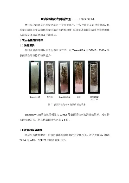
重油污清洗表面活性剂-----Texent610A 摩托车化油器是汽油发动机的一个重要部件,一般使用的是铝合金金属,化油器的清洗需要去除化油器内部的油污和积碳,以保证其表面的洁净度和粘附性,从而保证其重新使用及使用寿命。
1.表面活性剂的选择
1.1油泥清洗
按照金属清洗国标中去污力测试方法,对Texent610A与NP-10、226SA等表面活性比较除矿物油能力。
图 1 表面活性剂对矿物油的清洗效果
Texent610A的清洗效果明显比226SA等表面活性剂的清洗效果好,对矿物油清洗能力强,是其他表面活性剂的2-5倍。
1.2灰尘和积碳清洗
将灰尘与碳黑混合,均匀的散落在涂抹油污的金属片上,老化处理后,测试FAS-4与AES、OEP-70的除灰效果比较。
图 2 表面活性剂的除灰效果
FAS-4的除灰能力明显强于AES、OEP等表面活性剂,去污能力强,特别适合金属表面的除灰清洗。
2.配方清洗效果
基于化油器的表面污渍和金属材质,调整复配了合适的表面活性剂配方,清洗速度快,不腐蚀金属表面。
图 3 清洗前后对比。
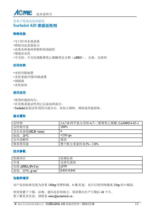
技术说明书
© 重庆艾克米科技有限公司 | SURFADOL 420表面活性剂 | 2018/12/26 1/1
非离子低泡动态润湿剂
Surfadol 420表面活性剂
特殊性能
•专门针对水基系统
•降低动态表面张力
•改善各种基材和颜料的润湿性
•增强亲水性
•不含硅,不含烷基酚聚氧乙烯醚类化合物(APEO ),无毒,无溶剂
应用实例
•水性印刷油墨
•水性柔版/凹版印刷油墨
•润版液
•水性涂料
使用说明
•使用时搅拌均匀。
•在其他表面活性剂之后添加和混合。
•Surfadol 表面活性剂均匀混合后,再加入颜料,填料或其他固体。
基本属性
技术参数
包装和储存
该产品的标准包装为净重180kg 的塑料桶,4桶/托盘。
也可以使用吨桶或25kg 的小桶装。
密封放置于干燥、凉爽、通风良好的地方。
保持期为生产日期后48个月。
想了解更多信息,请联系sales@ 。
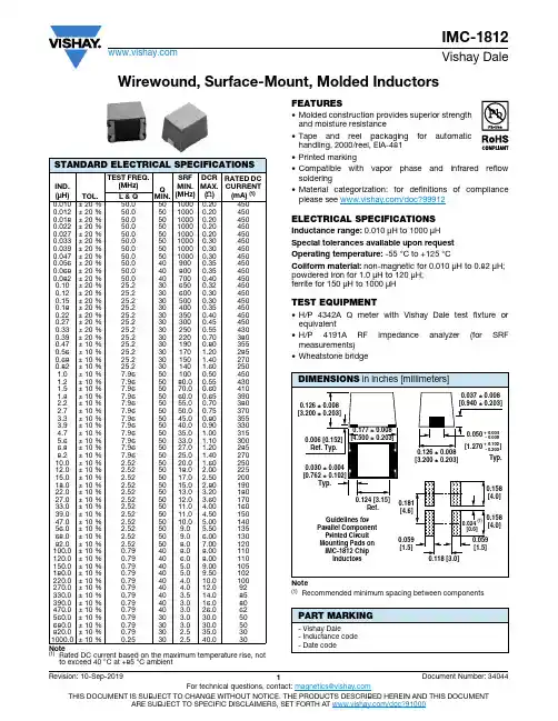
Wirewound, Surface-Mount, Molded InductorsNote(1)Rated DC current based on the maximum temperature rise, notto exceed 40 °C at +85 °C ambient FEATURES•Molded construction provides superior strength and moisture resistance•Tape and reel packaging for automatic handling, 2000/reel, EIA-481•Printed marking•Compatible with vapor phase and infrared reflow soldering•Material categorization: for definitions of compliance please see /doc?99912ELECTRICAL SPECIFICATIONSInductance range: 0.010 μH to 1000 μHSpecial tolerances available upon request Operating temperature: -55 °C to +125 °CCoilform material: non-magnetic for 0.010 μH to 0.82 μH; powdered iron for 1.0 μH to 120 μH; ferrite for 150 μH to 1000 μHTEST EQUIPMENT•H/P 4342A Q meter with Vishay Dale test fixture or equivalent•H/P 4191A RF impedance analyzer (for SRF measurements)•Wheatstone bridgeNote(1)Recommended minimum spacing between componentsSTANDARD ELECTRICAL SPECIFICATIONSIND.(μH)TOL.TEST FREQ.(MHz)QMIN.SRFMIN.(MHz)DCR MAX.(Ω)RATED DCCURRENT (mA) (1)L & Q0.010± 20 %50.05010000.204500.012± 20 %50.05010000.204500.018± 20 %50.05010000.204500.022± 20 %50.05010000.204500.027± 20 %50.05010000.204500.033± 20 %50.05010000.304500.039± 20 %50.05010000.304500.047± 20 %50.05010000.304500.056± 20 %50.0409000.354500.068± 20 %50.0408000.354500.082± 20 %50.0407000.404500.10± 20 %25.2306500.324500.12± 20 %25.2306000.304500.15± 20 %25.2305000.304500.18± 20 %25.2304000.354500.22± 20 %25.2303500.404500.27± 20 %25.2303000.454500.33± 20 %25.2302500.554300.39± 20 %25.2302200.703800.47± 10 %25.2301900.803550.56± 10 %25.230170 1.202850.68± 10 %25.230150 1.402700.82± 10 %25.230140 1.602501.0± 10 %7.96501000.504501.2± 10 %7.965080.00.554301.5± 10 %7.965070.00.604101.8± 10 %7.965060.00.653902.2± 10 %7.965055.00.703802.7± 10 %7.965050.00.753703.3± 10 %7.965045.00.803553.9± 10 %7.965040.00.903304.7± 10 %7.965035.0 1.003155.6± 10 %7.965033.0 1.103006.8± 10 %7.965027.0 1.202858.2± 10 %7.965025.0 1.4027010.0± 10 % 2.525020.0 1.6025012.0± 10 % 2.525018.0 2.0022515.0± 10 % 2.525017.0 2.5020018.0± 10 % 2.525015.0 2.8019022.0± 10 % 2.525013.0 3.2018027.0± 10 % 2.525012.0 3.6017033.0± 10 % 2.525011.0 4.0016039.0± 10 % 2.525011.0 4.5015047.0± 10 % 2.525010.0 5.0014056.0± 10 % 2.52509.0 5.5013568.0± 10 % 2.52509.0 6.0013082.0± 10 % 2.52508.07.00120100.0± 10 %0.79408.08.00110120.0± 10 %0.7940 6.08.00110150.0± 10 %0.7940 5.09.00105180.0± 10 %0.7940 5.09.50102220.0± 10 %0.7940 4.010.0100270.0± 10 %0.7940 4.012.092330.0± 10 %0.7940 3.514.085390.0± 10 %0.7940 3.016.080470.0± 10 %0.7940 3.026.062560.0± 10 %0.7930 3.030.050680.0± 10 %0.7930 3.030.050820.0± 10 %0.7930 2.535.0301000.0± 10 %0.2530 2.540.030PART MARKING- Vishay Dale- Inductance code - Date codeDESCRIPTIONIMC-181210 μH± 10 %ER e3MODEL INDUCTANCE VALUE INDUCTANCE TOLERANCE PACKAGE CODE JEDEC® LEAD (Pb)-FREE STANDARDGLOBAL PART NUMBERI M C1812E R100KPRODUCT FAMILY SIZE PACKAGECODEINDUCTANCEVALUETOL.Legal Disclaimer Notice VishayDisclaimerALL PRODUCT, PRODUCT SPECIFICATIONS AND DATA ARE SUBJECT TO CHANGE WITHOUT NOTICE TO IMPROV E RELIABILITY, FUNCTION OR DESIGN OR OTHERWISE.V ishay Intertechnology, Inc., its affiliates, agents, and employees, and all persons acting on its or their behalf (collectively,“Vishay”), disclaim any and all liability for any errors, inaccuracies or incompleteness contained in any datasheet or in any other disclosure relating to any product.Vishay makes no warranty, representation or guarantee regarding the suitability of the products for any particular purpose or the continuing production of any product. To the maximum extent permitted by applicable law, Vishay disclaims (i) any and all liability arising out of the application or use of any product, (ii) any and all liability, including without limitation special, consequential or incidental damages, and (iii) any and all implied warranties, including warranties of fitness for particular purpose, non-infringement and merchantability.Statements regarding the suitability of products for certain types of applications are based on Vishay's knowledge of typical requirements that are often placed on Vishay products in generic applications. Such statements are not binding statements about the suitability of products for a particular application. It is the customer's responsibility to validate that a particular product with the properties described in the product specification is suitable for use in a particular application. Parameters provided in datasheets and / or specifications may vary in different applications and performance may vary over time. All operating parameters, including typical parameters, must be validated for each customer application by the customer's technical experts. Product specifications do not expand or otherwise modify Vishay's terms and conditions of purchase, including but not limited to the warranty expressed therein.Hyperlinks included in this datasheet may direct users to third-party websites. These links are provided as a convenience and for informational purposes only. Inclusion of these hyperlinks does not constitute an endorsement or an approval by Vishay of any of the products, services or opinions of the corporation, organization or individual associated with the third-party website. Vishay disclaims any and all liability and bears no responsibility for the accuracy, legality or content of the third-party website or for that of subsequent links.Except as expressly indicated in writing, Vishay products are not designed for use in medical, life-saving, or life-sustaining applications or for any other application in which the failure of the Vishay product could result in personal injury or death. Customers using or selling Vishay products not expressly indicated for use in such applications do so at their own risk. Please contact authorized Vishay personnel to obtain written terms and conditions regarding products designed for such applications. No license, express or implied, by estoppel or otherwise, to any intellectual property rights is granted by this document or by any conduct of Vishay. Product names and markings noted herein may be trademarks of their respective owners.© 2022 VISHAY INTERTECHNOLOGY, INC. ALL RIGHTS RESERVED。
TiAlSiN纳米复合涂层的研究进展目录1. 内容概括 (2)1.1 TiAlSiN涂层特性及应用概述 (2)1.2 纳米复合涂层的优势及发展趋势 (3)1.3 本文研究内容与创新之处 (5)2. TiAlSiN涂层结构与表征 (6)2.1 TiAlSiN涂层相组成与缺陷 (7)2.2 TiAlSiN涂层显微结构及形貌表征 (7)2.3 TiAlSiN涂层物性表征方法 (9)3. TiAlSiN纳米复合涂层制备方法 (10)3.1 物理气相沉积法 (11)3.1.1 溅射沉积 (12)3.1.2 磁控溅射 (13)3.1.3 等离子射束沉积 (14)3.2 化学气相沉积法 (16)3.3 高能离子注入技术 (17)3.4 其他制备方法 (18)4. TiAlSiN纳米复合涂层性能优化 (19)4.1 工艺参数优化 (20)4.2 添加剂调控 (21)4.3 后処理技术 (23)5. TiAlSiN纳米复合涂层应用研究 (24)5.1 轴承件耐磨性 (25)5.2 刀具材料高硬度 (27)5.3 热场环境应用 (27)5.4 其他应用领域 (29)6. 结论与展望 (30)1. 内容概括本文主要探讨了TiAlSiN纳米复合涂层的研究进展。
首先概述了纳米复合涂层的重要性,其不仅拥有优异的物理和化学性能,而且在多种应用领域具有广泛的应用前景。
文章详细介绍了TiAlSiN纳米复合涂层的制备技术,包括物理气相沉积(PVD)、化学气相沉积(CVD)以及溶胶凝胶法等方法的最新研究进展。
文章接着介绍了这种纳米复合涂层的性能特点,包括硬度、耐磨性、耐腐蚀性和高温稳定性等,并对其性能优化方法进行了探讨。
文章还涉及TiAlSiN纳米复合涂层在各个领域的应用现状,包括机械零件、刀具、汽车零部件等。
本文总结了当前研究的不足之处和未来研究方向,指出今后需要解决的问题和未来的发展趋势。
该领域需要进一步优化涂层的制备工艺,提高其性能并扩大应用领域,以实现工业的大规模应用和商业化的前景。
SpeedWave™ 300P 半固化片用于混压板的加工指南SpeedWave™是一种使用了玻璃布增强以及超低损耗树脂体系的复合材料,可以用于粘结罗杰斯公司生产的多种覆铜板,包括RO1200, CL TE-MW和RO4000®系列。
本加工指南,是为客户提供使用SpeedWave半固化片应用芯板压合或铜箔压合工艺加工多层混压线路板的基本信息。
第一次使用SpeedWave半固化片的客户,请在使用前联系罗杰斯公司的技术服务工程师提供技术指导。
储存:一旦收到产品后,需要马上将其从收货区转移至受控的环境中。
合适的存储环境是温度<23°C, 相对湿度<55%。
使用后剩余的材料应该装入防潮袋内,以免吸潮。
应避免在高湿度的环境下使用,否则会导致材料性能的恶化。
若符合上述储存条件,半固化片的保质期为出货日起3个月。
建议采用“先进先出”的库存系统。
工具孔加工:SpeedWave半固化片可以兼容于大多数典型的多层板对位系统。
工具孔可以冲孔、钻或切割。
氧化处理:内层图形的金属表面应采用化学处理,以提高铜与树脂的结合强度。
相对于传统的棕化或黑化处理,更推荐氧化替代法工艺。
压合:下面的压合参数建议适用于一次压合结构。
如果多层板设计需要多次压合,请咨询技术服务工程师。
低粗糙度的铜箔可以作为内层使用。
对外层铜箔附着力有要求时,推荐使用较高粗糙度的铜箔。
钻孔:在使用SpeedWave半固化片制作多层混压板时,多层板的钻孔参数应该遵循芯板材料的钻孔条件。
具体钻孔条件可以参考所用芯板材料的加工指南的建议。
亦可联系联系技术服务工程师,讨论具体的案例。
PTH和外层加工:钻孔后的去毛刺处理,建议使用高压气枪或水洗清除孔内疏松的碎屑。
推荐使用等离子体去钻污。
当选择使用等离子体去钻污,则需要跳过化学去钻污工艺。
如果选择化学去钻污工艺,则可能需要修改化学去钻污的程序。
具体请咨询技术服务工程师关于程序设置的建议。
如果与聚四氟乙烯材料搭配做混合多层板结构,在化学沉铜之前的除胶工艺之后需要做一次等离子体活化处理。
1.目的 :1.1旨在确保按正确方法作业,防止人为误操作造成分析不准确而拟定。
2.适用范围:2.1 适用于伟信电子OSP表面处理制程药液之分析。
3.权责:3.1化验室:按规范进行作业。
4.名词解释:无5.作业内容:作業流程:按《药液管理规范》运作 。
作業说明:如页次3-4 。
6.参考文件:《药液管理规范》《化验室管理规范》7.记录表单:7.1《化验分析报告单》2011.03.265.15.26.26.1OSP 表面处理液分析规范版本(次)B 生效日期作业说明:5.2.1OSP表面处理液分析方法:1>除油槽A .清洁剂a.所需药品:酚酞(P.P.)指示剂、1N-NaOHb.所需仪器:吸量管、锥形瓶、滴定管c.分析方法:<1>取試樣10ml於250ml锥形瓶中,加100ml D.I水;<2>加入2-3滴酚酞(P.P.)指示剂;<3>以1N-NaOH滴定至粉红色為終點.d.计算:清洁剂浓度(%)=滴定ml數×0.83×N 2>微蝕槽⑴H 2SO 4的分析方法:取2ml槽液于250ml锥形瓶中,加50ml纯水再加入3-5滴甲基橙指示剂,用1N NaOH滴定至黄色为终点。
计算:H 2S04% = V*1.33*N⑵Na 2S 2O 8的分析方法:取1ml槽液于250ml锥形瓶中,加20ml纯水,加入Na 2S 2O 3标准溶液滴定至淡黄色时加入数滴淀粉指示剂,继续滴定至溶液呈乳白色为终点,记下滴定体积。
计算:Na 2S 2O 8(g/l)=0.1*V 0.1N硫代硫酸钠*119⑶铜离子的分析方法:取1ml槽液于250ml锥形瓶中,加40ml纯水,再加20mlPH=10缓冲液,加5-6滴PAN指示剂,用0.1nEDTA滴定至草绿色。
计算:CU 2+=N*V*63.54B 生效日期2011.03.26OSP 表面处理液分析规范版本(次)5.2主槽:(1)YSF-160R1分析方法:1、准确取10ml防氧化剂YSF-160R1原液到100ml容量瓶中用纯水稀释至刻度放装满,放入UV仪记录吸光度N1;6、取出石英比色皿,用步骤3中配好的稀释槽液冲洗石英比色皿并装满 ,入UV仪记录吸光度N2.计算:YSF-160R1%=N2/N1*10(2)YSF-160R2分析方法仪器:25ml移液管,250ml锥形瓶试剂:1N NaOH;0.1%中性红指示剂;分析步骤;1. 取25 ml槽液于250 ml锥形瓶中;2. 加约150 mL纯水,2 – 3 滴中性红指示剂;3. 用1.0N NaOH滴定至红色消失为终点,记录消耗量毫升数V。
T ranslink-37表面处理煅烧高岭土BASF ENGAHARD基本技术资料产品说明:Translink 37 是高白度、微细粒径的高岭土。
通过受控热处理,产品晶体中的羟基被去除后而改善产品的亮度。
经研磨而成的Translink 37 高岭土微细颗粒分散性好,产品经过乙烯基硅烷表面处理,同时残余物极低。
应用信息:Translink 37 高岭土作为一种高性能的增强剂广泛应用于聚乙烯、乙丙橡胶聚合物为基的中压系统电气设计,以达到降低水对系统渗透性。
同时,低残余物也降低了对绝缘性能以及挤出加工性能的不利影响。
Translink 37 高岭土为电气产品应用提供了优良的初期和长期的抗湿性能,推荐用于采用过氧化物硫化工艺的产品中使用。
典型的应用:酚醛塑料、乙丙橡胶电缆、医用橡胶、聚酯凝胶涂层、插座、电容器、TPE/TPO、电线护套、以及硅橡胶。
产品指标:物理形态:粉末特殊处理:去羟基/表面处理白度(%):91 筛余物, 325 (%):0.02*游离水分@ 105 C (%):0.5 pH值(28% 固体):N/A比重(克/立方厘米):2.63 平均粒径(μm):1.4*堆积密度-游离态(磅/立方英尺;千克/立方米):17 / 270堆积密度-夯实态(磅/立方英尺;千克/立方米):35 / 560吸油值(美国材料试验协会D-281):50 折光率:1.62膨胀值(磅每伽/公斤每升):21.9 / 2.62*以上数值基于未经处理的产品所有的Engelhard 高岭土的制造设备都经过ISO–9002资格认证进一步的信息:上所描述的产品特性信息为总体概括,不能用来作为产品的说明书使用。
产品的性能会根据特定的应用而改变。
所有的产品都要在消费者使用之前得到检测试验。
Engelhard 一直致力于提供真实可信的有关与产品的组成成分、性质性能以及关于产品使用方法的信息。
所有的资料、建议、以及其他的任何关于产品,服务或程序的等信息资料都是免费提供,但不存在任何担保承诺。