S7-300-400联机调试使用说明
- 格式:pdf
- 大小:6.01 MB
- 文档页数:69
西门子s7300的pid实例西门子S7_300_400PID模块参数说明和使用方法导读:就爱阅读网友为您分享以下“西门子S7_300_400PID模块参数说明和使用方法”资讯,希望对您有所帮助,感谢您对的支持!Machinery&Equipment机械与装备西门子S7-300/400PID模块参数说明和使用方法汤顺斌(KHS广东轻工机械二厂有限公司,广东汕头515061)摘要:国内的啤酒、饮料包装行业大量应用西门子S7-300/400PLC作为主控系统。
在这些行业中,用户经常要对温度、压力、流量、等模拟量做PID处理。
就S7-300/400PLC 的PID模块的参数说明和使用方法与各位交流。
关键词:PID;模块参数中图分类号:TS7203文献标识码:CPID是英文比例、积分、微分各取第一个字母P_SEL:BOOL:比例选择位:该位ON时,选择P的缩写,PID控制器是应用最广泛的闭环控制器,(比例)控制有效;一般选择有效;据估计90%的闭环控制采用PID算法。
I_SEL:BOOL:积分选择位;该位ON时,选择FB41称为连续控制的PID用于控制连续变化(I积分)控制有效;一般选择有效;的模拟量,与FB42的差别在于后者是离散型的,INT_HOLDBOOL:积分保持,不去设置它;用于控制开关量,其他二者的使用方法和许多参I_ITL_ONBOOL:积分初值有效,I-ITLV AL(积数都相同或相似。
分初值)变量和这个位对应,当此位ON时,则使用PID的初始化可以通过在OB100中调用一次,I-ITLVAL 变量积分初值。
一般当发现PID功能的将参数COM-RST 置位,当然也可在别的地方初始积分值增长比较慢或系统反应不够时可以考虑使化它,关键的是要控制COM-RST。
用积分初值;PID的调用可以在OB35中完成,一般设置时D_SEL:BOOL:微分选择位,该位ON时,选择间为200MS,一定要结合STEP7V5.3帮助文档中D(微分)控制有效;一般的控制系统不用;的PID框图研究以下的参数,可以起到事半功倍CYCLE:TIME:PID采样周期,一般设为200MS;的效果。
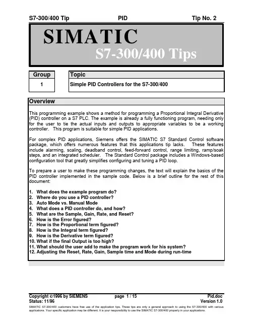
Group Topic1Simple PID Controllers for the S7-300/400OverviewThis programming example shows a method for programming a Proportional Integral Derivative (PID) controller on a S7 PLC. The example is already a fully functioning program, needing only for the user to tie the actual inputs and outputs to appropriate variables to be a working controller. This program is suitable for simple PID applications.For complex PID applications, Siemens offers the SIMATIC S7 Standard Control software package, which offers numerous features that this applications tip lacks. These features include alarming, scaling, deadband control, feed-forward control, range limiting, ramp/soak steps, and an integrated scheduler. The Standard Control package includes a Windows-based configuration tool that greatly simplifies configuring and tuning a PID loop.To prepare a user to make these programming changes, the text will explain the basics of the PID controller implemented in the sample code. Below is a brief outline for the rest of this document:1.What does the example program do?2.Where do you use a PID controller?3.Auto Mode vs. Manual Mode4.What does a PID controller do, and how?5.What are the Sample, Gain, Rate, and Reset?6.How is the Error figured?7.How is the Proportional term figured?8.How is the Integral term figured?9.How is the Derivative term figured?10.What if the final Output is too high?11.What should the user add to make the program work for his system?12.Adjusting the Reset, Rate, Gain, Sample time and Mode during run-timePID ExploredWhat does the example program do?示例程序的用途?This programming example is a skeleton program for a true PID controller and, as such, requires that the user make a few additions (i.e. read/write input/output variables) before it is fully functional. Before discussing these, however, let’s get a better feel for what a PID program actually does through a brief example.When do you use a PID controller?Figure 2.1 shows a picture of an example system to which a user might connect a PID controller. The figure shows a water tank sitting atop a hot plate, with a temperature control device for the hot plate and a small, monitored turbine for measuring the rate of the steam flow. This is a system that will work with a PID controller because of the relationship between the two variables: You can directly control the steam flow rate by adjusting the temperature of the hot plate. Figure 2.2 shows how both variables relate to the PID controller.The variable which represents the state of the system being controlled is called the ‘Process Variable.’ In our example above, you can see that the rate at which the steam spins the turbine is a good indicator of the event that we are trying to control: the speed at which the water is being boiled off. The output is the variable which, being altered by the controller, can affect the process variable by different degrees based on its intensity -- By turning the hot plate up, the water boils more quickly, more steam is produced, and the turbine’s speed increases. Therefore, when a variable that accurately reflects the state of the process and an adjustable control which proportionally affects the process variable, then it is possible to use a PID controller. Common systems using PID controllers are air conditioning systems, solution mixing, heaters, etc.Auto Mode vs. Manual Mode自动模式和手动模式There are two settings available on our PID controller. Putting a controller in Manual mode causes the PID loop do nothing, so that the user can directly control the output. The second, Auto, is the mode in which the PID loop is actually controlling the system. For the rest of this text, it will be assumed that the controller is in Auto mode.What does the PID controller do, and how does it do it? PID控制器作些什么?如何去做?Quite simply, a PID controller adjusts the value of its output to try and balance the value of the process variable to a given ‘setpoint.’To calculate the output value for a given instance, the controller finds the value of three different terms (using its user defined Sample time, Gain, Rate, and Reset values along with the calculated Error value): a Proportional term, an Integral term, and a Derivative term.Output = M P + M I + M DFormula 2.1What are the Sample, Gain, Rate, and Reset, and where do they come from?The sample rate is the cycle time (in milliseconds) at which the PID loop recalculates the output. The gain controls the sensitivity of the output calculation by affecting the influence of all the terms. The reset is a time given in milliseconds which is used to increase or decrease the influence of the Integral term in the equation. Finally, the rate value is used to control the influence of the Derivative term in the equation. Each of these values needs to be preset by the user before the PID controller starts.If the user does not want integral action (no I in the PID calculation), then a value of infinity or a value of 0 should be specified for the integral time. If the user does not want derivative action (no D in the PID calculation), then a value of 0 should be specified for the derivative time. If the user does not want proportional action (no P in the PID), then a value of 0 should be specified for the gain (gain is normally a multiplier in the integral and derivative coefficient calculation, but is removed from the coefficient calculation, if gain = 0, to allow I, ID, or D loop control).How is the Error figured? 误差是如何计算的?Error is figured as the difference between the normalized values of the setpoint and the process variable. The controller calculates this value in three steps. The first two steps are to change both the setpoint and the process variable into values that are based on a 0 to 1 (normalized) scale. This is done using the formulae:SP = raw_SP / max_valPV = raw_PV / max_valFormulae 2.2 & 2.3In the above formulae, the raw_SP and raw_PV values are the actual values that come into the controller, and the max_val term is the maximum value that either can take on. For example, ifthe values of raw_SP and raw_PV were being read in as values from 0 to 27,648, then the max_val term would have the value 27,648.After these two values have been calculated, the error term is figured as follows:Error = SP - PVFormula 2.4How is the Proportional term calculated?The proportional term, M P, is calculated using the following equation:M P = Gain * ErrorFormula 2.2Going back to our earlier example with the water tank, the proportional term says that as the speed of the turbine increases further above the setpoint, the heat is decreased proportionally to bring the speed down. As the turbine slows below the setpoint, the heat is increased to proportionally to bring the speed up.How is the Integral Term calculated? 积分项如何计算?The integral term, M I, is calculated using the following equation:M I = Bias + (C I * Error)Formula 2.3In this equation, two new terms are introduced. The first, C I, is the coefficient系数 of the Integral term, and is calculated from the Reset:C I = Gain * (Sample / Reset)Formula 2.4Both the Sample and Reset terms were introduced earlier, but in this equation their uses become apparent. The larger the Reset value is, the less impact the integral term will have onthe output, while larger Sample times give it a bigger influence (Sample time also affects the Derivative term, which will be explained later).The Bias term in Formula 2.3 represents (technically speaking) the area under the curve of a graph plotting the Error vs. time.Abstractly, however, the Bias value (ideally) grows to an output level that keeps the system stable, letting the Proportional and Derivative terms handle any small fluctuations. In relation to our water tank example from earlier, this means that eventually the Bias portion of M I would be the only significant contribution to the final output value, and the M P and M D terms would only be active (non-zero) when a fluctuation occurred.At a time n the equations for M I and the Bias term are:M I,n = Bias n-1 + (C I * Error)Bias n = M I,nFormula 2.5How is the Derivative term calculated?微分项如何计算?The derivative formula for a given time n is calculated with the following equation:M D = C D * (PV n-1 - PV n)Formula 2.6This formula only introduces 1 new term, C D, which is calculated using Formula 2.7.C D = Gain * (Rate / Sample)Formula 2.7The Sample term (which is also used in figuring C I) is the sample time from earlier. In the Derivative term, the Sample time is indirectly proportional to the derivative component, while the Rate is directly proportional.What if the final output value is too high?如果最终输出值太高怎么办?During many processes (such as the water tank example earlier), the Process variable doesn’t respond immediately to a change in the value of the output -- if the water in the tank were ice cold, then even an output of 100% is not going to cause an instantaneous increase in steam flow. Likewise, setting the output to 0% when the water is boiling doesn’t provide an immediate reduction in steam production.Because of this ‘system inertia,’ the output value for a give time could take on a value greater than 100% or less than 0%. In response to this, the PID program implements Output Clamping. If the output is greater than 100%, then it is clamped to 100%. If the output falls lower than 0%, then it is held to 0%.The only problem left to solve lies with the Bias portion of the Integral term. When the output for a system remains at 100% for a long period of time (such as when heating up cold water in our tank from earlier), the integral sum (which the Bias term represents) can grow to extremely large values. This means that when the variable starts responding, the Bias term will be keeping the calculated output well over 100% until it can be wound down. This generally results in the output swinging wildly from one limit to the other, but can be avoided using Bias Clamping. There are a few different types of Bias Clamping, but the only pertinent one here is the one used in the program. There are two different conditions which cause Bias clamping to occur and two formulae as well:If Output > 1Bias = 1 - (M P + M D)Formula 2.8If Output < 0Bias = -(M P + M D)Formula 2.9As the formulae show, when the Output grows to be greater than 1, the value of the Bias is adjusted so that the sum of M P, M D, and the Bias will be 1. Likewise, when the Output slips below 0, the value of the Bias is adjusted so that the above sum will be 0. The adjusted Bias value is then clamped such that its maximum value is 1 and its minimum value is 0.What should be added to make the program work for the system?1. Read in the Process Variable2. Write the Output3. Set the Setpoint4. Adjust the scale for the Input and Setpoint5. Adjust the scale for the Output6. Adjust the Reset, Rate, Gain, and Sample time values.Read in the Process VariableThe Process variable (the variable which accurately reflects the state of the system to be controlled) should be passed to the PV parameter of the function block.Write the OutputThe OUT parameter of the PID loop should be set to the analog output being controlled in the PID function block call.Set the SetpointThe user’s code must pass the Setpoint value to the PID function block via the SP parameter.Adjust the scale for the Process Variable and Setpoint 调整过程值和设定点值。
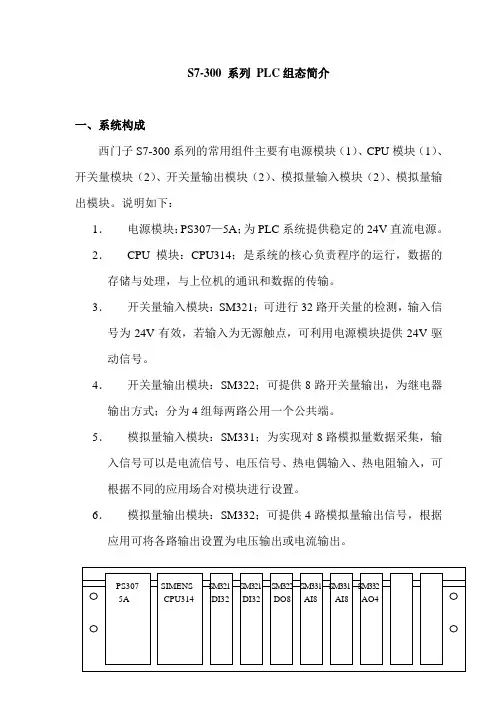
S7-300 系列PLC组态简介一、系统构成西门子S7-300系列的常用组件主要有电源模块(1)、CPU模块(1)、开关量模块(2)、开关量输出模块(2)、模拟量输入模块(2)、模拟量输出模块。
说明如下:1.电源模块:PS307—5A;为PLC系统提供稳定的24V直流电源。
2.CPU模块:CPU314;是系统的核心负责程序的运行,数据的存储与处理,与上位机的通讯和数据的传输。
3.开关量输入模块:SM321;可进行32路开关量的检测,输入信号为24V有效,若输入为无源触点,可利用电源模块提供24V驱动信号。
4.开关量输出模块:SM322;可提供8路开关量输出,为继电器输出方式;分为4组每两路公用一个公共端。
5.模拟量输入模块:SM331;为实现对8路模拟量数据采集,输入信号可以是电流信号、电压信号、热电偶输入、热电阻输入,可根据不同的应用场合对模块进行设置。
6.模拟量输出模块:SM332;可提供4路模拟量输出信号,根据应用可将各路输出设置为电压输出或电流输出。
图1、系统模块组成。
二、硬件组态1.基本机架(中心机架)机架即是用于安装固定各个模块的专用槽架。
PLC的各个模块就遵循一定的规则固定在上面。
每个机架中:插槽1为电源模板插槽;插槽2为CPU模板插槽;插槽3留给通讯模板接口模板及扩展模板。
插槽4以后留给应用模板。
每个模块最多可以安装8个应用模块。
模块的底部通过总线连接器与前后的模块想连接,构成一个整体系统。
中心机架至少应装配电源模块和CPU模块,再根据需要配置其他功能模块。
说明:所谓插槽,在这里只是抽象的概念,S7—300系统中的机架物理形态上只是一个槽形轨道,上面没有具体的插槽,模块也只是按一定顺序固定在上面,模块之间也无须保留空间,而是紧密地相邻安装。
插槽的概念只有在对系统进行软件组态时才能具体化。
(软件组态将在后面介绍)2.机架的扩展当基本机架不能满足系统要求时,可通过扩展机架对系统进行扩展,扩展方式有两种:①、用IM365模板:可扩展一个机架,需用两块IM365模板,连接长度最长为一米。

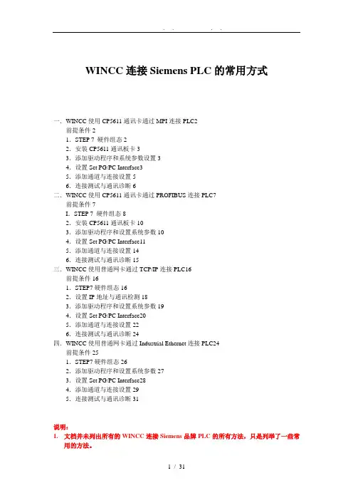
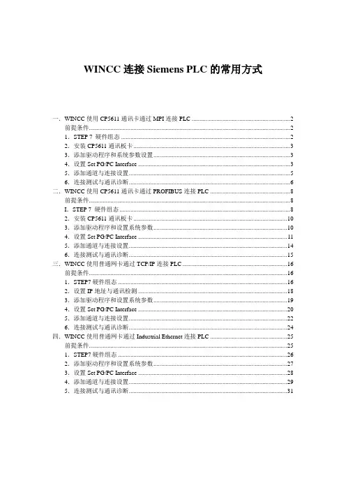
WINCC连接Siemens PLC的常用方式一.WINCC使用CP5611通讯卡通过MPI连接PLC2前提条件21.STEP 7 硬件组态22.安装CP5611通讯板卡33.添加驱动程序和系统参数设置34.设置Set PG/PC Interface35.添加通道与连接设置56.连接测试与通讯诊断6二.WINCC使用CP5611通讯卡通过PROFIBUS连接PLC7前提条件7I.STEP 7 硬件组态82.安装CP5611通讯板卡103.添加驱动程序和设置系统参数104.设置Set PG/PC Interface115.添加通道与连接设置146.连接测试与通讯诊断15三.WINCC使用普通网卡通过TCP/IP连接PLC16前提条件161.STEP7硬件组态162.设置IP地址与通讯检测183.添加驱动程序和设置系统参数194.设置Set PG/PC Interface205.添加通道与连接设置226.连接测试与通讯诊断24四.WINCC使用普通网卡通过Industrial Ethernet连接PLC24前提条件251.STEP7硬件组态262.添加驱动程序和设置系统参数273.设置Set PG/PC Interface284.添加通道与连接设置295.连接测试与通讯诊断31说明:1.文档并未列出所有的WINCC连接Siemens品牌PLC的所有方法,只是列举了一些常用的方法。
2.在各种连接方式中的参数设置可能会略有不同,在此列出的步骤和参数只是一套可以连通的设置方法。
一.WINCC使用CP5611通讯卡通过MPI连接PLC前提条件I〕通过CP5611实现PLC系统与WINCC6.0通讯的前提条件是在安装有WINCC的计算机上安装CP5611通讯板卡。
II〕使用STEP7编程软件能够通过MPI正常连接PLC。
1.STEP 7 硬件组态STEP7设置MPI通讯,具体步骤不在此详述,可参考如以下图1.1示:图1.1注意:1.新建一个MPI网络用来通讯,设置MPI网络的地址和波特率,且记住,在随后的设置中需要匹配。
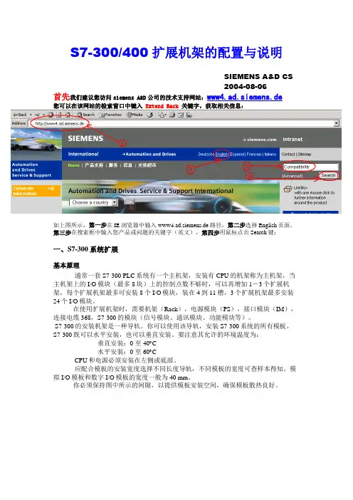
S7-300/400扩展机架的配置与说明SIEMENS A&D CS2004-08-06首先我们建议您访问siemens A&D公司的技术支持网站:www4.ad.siemens.de您可以在该网站的检索窗口中键入 Extend Rack 关键字,获取相关信息:如上图所示,第一步在IE浏览器中输入www4.ad.siemens.de路径,第二步选择English页面,第三步在搜索框中输入您产品或问题的关键字(英文),第四步用鼠标点击Search键;一、S7-300系统扩展基本原理通常一套S7-300 PLC系统有一个主机架,安装有CPU的机架称为主机架,当主机架上的I/O模块(最多8块)上的控制点数不够时,可以再增加1-3个扩展机架,每个扩展机架最多可安装8个I/O模块,装在4到11槽,3个扩展机架最多安装24个I/O模块。
在使用扩展机架时,需要机架(Rack),电源模块(PS),接口模块(IM),连接电缆368,S7-300的模块(信号模块、通讯模块、功能模块等)。
S7-300的安装机架是一种导轨。
你可以使用该导轨,安装S7-300系统的所有模板。
S7-300既可以水平安装,也可以垂直安装。
要注意其允许的环境温度为:垂直安装:0 至 40︒C水平安装:0 至 60︒CCPU和电源必须安装在左侧或底部。
应配合模板的安装宽度选择不同长度导轨,不同模板的宽度可查样本得知,模拟I/O模板和数字I/O模板的宽度一般为40 mm。
你必须保持图中所示的间隙,以提供模板安装空间,确保模板散热良好。
图1-1 间隙使用单机架或多机架是使用一个机架还是使用多个机架,取决于具体情况。
在下面的情况下应该使用单机架: ∙ 结构紧凑、需要节约空间∙ CPU312、312 IFM 、312C 和CPU 313只能用单机架 ∙ 所需处理的信号量少在下面的情况下应该使用多机架:所需处理的信号量大没有足够的插槽如需将S7-300装在几个机架上,则需要接口模板(IM ),接口模板的使命是将S7-300背板总线从一个机架扩展到下一个机架。
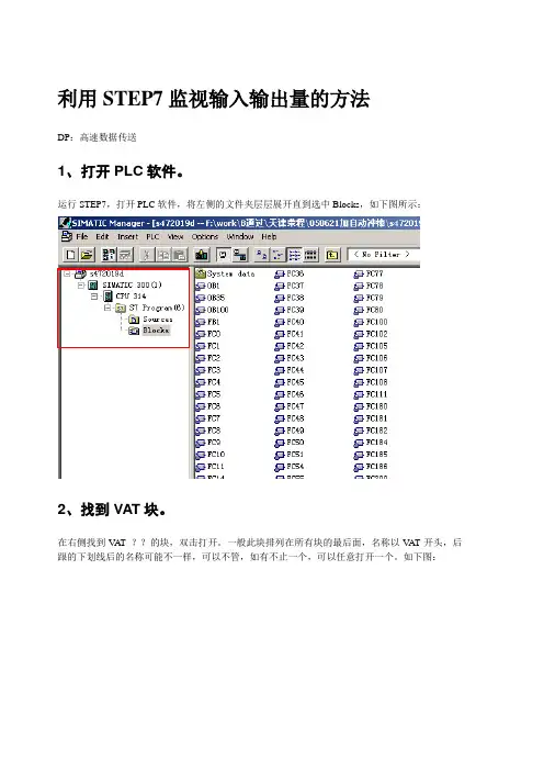
利用STEP7监视输入输出量的方法DP:高速数据传送1、打开PLC软件。
运行STEP7,打开PLC软件,将左侧的文件夹层层展开直到选中Blocks,如下图所示:2、找到VAT块。
在右侧找到V AT_??的块,双击打开。
一般此块排列在所有块的最后面,名称以V AT开头,后跟的下划线后的名称可能不一样,可以不管,如有不止一个,可以任意打开一个。
如下图:3、插入VAT块。
如没有找到此块,可以在自行添加一个,操作如下图,在右侧窗口空白处点击鼠标右键,选择Insert New Object(插入新对象)——Variable Table(变量表)4、选中后将出现如下窗口5、打开VAT块。
点击OK按钮即可生成V A T_1块。
打开V A T块,如下图:6、查找监视点地址。
在Address一列中输入想要监视的地址,如需要监视第一流自动转换开关状态,则察看接口表7、监视数字量输入点。
如上图,察看接口表得知,第一流转换开关的自动档输入点为I0.0,第二流转换开关的自动档输入点为I4.0。
将这两个地址输入到V AT窗口中的Address一栏中,如图:8、判断监视结果。
在第一行中输入I0.0后,回车后,光标自动移到第二行,第三列的Display format自动设为BOOL 类型。
在保证工控机与PLC联接正常的情况下,可以点上图方框所示的Monitor Variable按钮,则情况应如下图所示,窗口的标题栏变为高亮的青色,窗口右下角的RUN状态栏有绿色状态条不断闪动。
下图所示的监视结果,I0.0结果为绿色,true,I0.4结果为灰色,false,表明第一流转换开关处于手动档,第二流转换开关不处于手动档。
9、错误判断。
如在Address栏中输入要监视的量后字变为红色,说明输入有误,例如:10、修改显示格式。
所有的数字量输入输出点的数据类型都是BOOL型,即输入要监视的点后,使用系统给出的默认Display format(显示格式)BOOL就可以了,如要监视模拟量输入点(模拟量输出点无法用VAT 监视),应该将显示格式改为Decimal如下图所示,如需要监视第一流的液位采样输入点,看接口表得知,此点地址为386,则在V AT窗口的Address(地址)一栏中输入PIW386,在Display format 一栏中点右键,选择Decimal:11、监视模拟量输入。
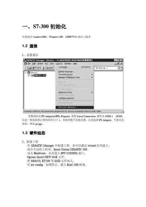
一、S7-300初始化尽量使用window2000,Windows XP。
STEP7V52或以上版本1.2 通信1、设置通信`设置或添加PC Adapter(MPI), Property 按钮Local Connection 属性页COM 1 19200,注意一般连接到计算机的串行口1。
其他参数不需要设置,注意选择PC Adapter,不要有其他的,例如pc/ppi。
1.3 硬件组态2、新建工程在SIMATIC Manager中新建工程,也可以通过wizard向导建立。
选中右边的工程名,Insert Station SIMATIC 300。
双击Hardware,从而进入HW CONFIG窗口。
Option>Insert NEW GSE文件。
把MM420, ET200等GSD文件加入。
在hw config,如图所示,插入RAC-300机架。
选中机架第二栏,双击CPU-300>CPU313C-2DP,注意准确的编号。
默认地址2。
双击DP,选择Property按钮。
选择NEW,选择1.5MBPS,如果出现警告,可以选择187kpbs。
依次在SLOT 1,2,3位置插入其他模块。
0 电源模块S7-300DI 地址:256-263DO 地址:256-259选中DP线,然后双击ET200S,如图所示,插入ET200S.选择,依次在SLOT 1,2,3位置插入其他模块。
6ES7 138-4CA00-0AA0 PM-E DC24V6ES7 134-4GB50-0AB0 2AI I 2DMU地址I address264-2676ES7 134-4JB50-0AB0 2AI RTD地址I address268-271插入MM420选择4PKW, 2PZD (PPO1)2AX地址I address 280-283 Q address 268-271全部保存1.4 下装硬件组态并检测在SIMATIC Manager中,选择工程,选择PLC>Clear/Reset,可以清除原来的配置信息。
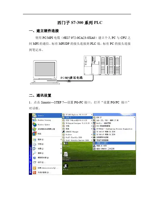
西门子S7-300系列PLC一、建立硬件连接使用PC/MPI电缆(6ES7 972-0CA23-0XA0)建立个人PC与CPU之间MPI的通信。
标有MPI/DP的接头连接到PLC端,标有PC的接头连接到笔记本。
二、通讯设置1.点击Simatic---STEP 7---设置PG-PC接口,打开“设置PG/PC 接口”对话框。
2.选中“PC Adapter(MPI)”,点击“属性”按钮。
3.在“MPI”下的为默认值即可。
4.在“本地连接”的“连接到(C):”中设置PC的COM口,如果使用的是USB线,则选择USB。
5.点击“确认”,返回到“设置PG/PC接口”对话框,点击“确认”,在跳出的路径更改对话框里点“确认”,完成设置。
三、使用STEP7编程软件上载程序1.打开STEP 7编程软件“SIMATIC Manager”。
2.点击“CANCEL”按钮即可,出现如下画面:3.点击“新建”按钮,建立一个新的项目。
4.输入新的项目名称,建立一个新的空项目例如“yyz”,然后点击“OK”按钮。
5.在“yyz”项目下,选择“PLC”菜单下的“Upload Station to PG”条目:6.出现上传选择对话界面,点击“VIEW”按钮,开始扫描。
选择在“Accessible Nodes”出现的CPU,再点击“OK”开始上传。
四、使用STEP7编程软件下载程序1.打开STEP 7编程软件“SIMATIC Manager”。
2.点击“Cancel”按钮。
3.点击“打开”,打开要下载的项目。
4.点击“SIMATIC 300(1)”,再点击“Download”图标。
再点击点击5.出现“Download”对话框,点击“Yes”,完成程序下载。
S7-300与S7-400之间的通信一.S7通信简介S7通讯是S7系列PLC基于MPI、PROFIBUS、ETHERNET网络的一种优化的通讯协议,主要用于S7300/400PLC之间的通讯。
SIMATIC S7-PN CPU包含了一个集成的PROFINET接口,该接口除了具有PROFINET I/O功能,还可以进行基于以太网的S7通信。
SIMATIC S7-PN CPU支持无确认数据交换、确认数据交换和单边访问功能。
功能块的使用如表1所示。
表1:块 S7-400 块S7-300 描述简要描述SFB8 FB8 用于发送无确认的快速数据交换,发送数据后无对方接收确认。
SFB9 FB9 用于接收SFB12 FB12 用于发送确认数据交换,发送数据后有对方接收确认。
SFB13 FB13 用于接收SFB14 FB14 读数据单边编程读访问。
SFB15 FB15 写数据单边编程写访问。
功能块的调用如图1、图2所示。
图1 S7-300功能块的调用图2 S7-400功能块的调用二.S7通信(S7 Communication)网络组态及参数设置1.新建项目及硬件组态在STEP 7中建立一个新的项目,点击右键,弹出的菜单中选择“Insert New Object”“SIMATIC 300 Station”,插入S7-300站,同理插入一个S7-400站,如图3所示。
在硬件组态中,分别插入CPU 315-2PN/DP和CPU 414-2,如图4所示。
图3 新建项目图4 硬件组态2.网络组态设置CPU 315-2PN/DP的属性,新建以太网并设置IP地址。
同样的方法,建立连接另一个S7-400的站,CP模板为CP 443-1,设置CP模板的IP 地址,连接到同一个网路“Ethernet(1)上”,如图5所示。
图5 设定IP地址在NetPro中组态连接。
选中S7-400站CPU,通过菜单“Insert>New Connection”插入一个新的连接。
S7-300 400 PLC 系统软件冗余调试的常见问题问题1:硬件组态需要注意什么?回答:软冗余系统的冗余控制只能通过ET 200M实现,按照图1进行组态。
A、B站的组态必须确保一致,可以拷贝ET200M的组态,在另一站点组态中使用图2所示菜单操作。
图1图2问题2:哪些模块可以支持软冗余?回答:可以通过软冗余手册查询,或参考以下链接的FAQ。
问题3:FC100“SWR_START”中定义的数据区,哪些是冗余数据区?哪些是非冗余数据区?有什么区别?回答:如图3红色区域,冗余同步数据区包括:过程映像输出区/DB/IEC/M;如图3绿色区域,非冗余数据区包括:DB。
冗余数据区,主站的数据会通过冗余链路覆盖到备用站,保证主备之间数据同步;非冗余DB区,无论主备,数据按照定义的A-B B-A方向传递。
注意!无论冗余数据区还是非冗余数据区,A、B站点的长度必须一致。
如果不需要使用,长度定义为0。
图3问题4:软冗余中DB块的影响。
回答:软冗余系统中会使用一些特殊功能的DB块,在FC100“SWR_START”中定义,如图4:图4A:软冗余工作DB,程序会自动生成,不要在项目中手动添加;“DB_SEND_NO”、“DB_RCV_NO”定义的DB,在冗余站两侧一致。
B: FB101“SWR_ZYK”的背景数据块,注意生成DB5的长度。
如果创建出错,CPU能够正常运行但是SF灯报错,诊断缓冲区如图5:图5查看DB5的长度如图6,只有100字节,此时双击打开DB5看不到内部参数,如图7。
可以删除DB5,重新生成FB101“SWR_ZYK”背景数据块。
正常MPI同步-194字节;以太网/PROFIBUS同步-358字节。
图6图7C:冗余DB区,主站的数据随时同步备用站。
需要手动创建,IEC定时器的背景数据块也需要生成,A、B站点长度一致;生成的DB块的长度需要大于2个字(新生成的DB块,内部只有一个INT变量,长度2字节)。
Siemens s7-400plc 与s7-300联机实验一:西门子多PLC连接方法。
1、MPI连接2、profibus连接1、MPI连接:验证西门子PLC之间可采用MPI方式直接连接。
实验器材:S7-400 CPU414-2DPS7-300 CPU315-2DPMPI连接线:九针,九针,3-3,8-8脚,编程PC-Adapter硬件配置:S7-400:完成400PLC的硬件配置,在HW-config中双击MPI/DP口,设置为MPI方式,并配置MPI网络,站号为:2S7-300:完成300PLC的硬件配置,在HW-config中双击CPU315 2DP,并配置MPI网络,MPI站号为3。
完成以上设备后,双击congfig-ure Network,在弹出窗体中选用MPI连接的粗线,右击MPI网络连线在弹出下拉菜单中单击Define Global Data,弹出MPI网络配置窗体,在窗体中选中一列(点击列上灰色部分),右击弹出CPU下拉菜单,点击CPU在弹出窗体中选中项目中需连接的CPU,CPU414-2DP点击OK,同样在第二列操作中选中300 CPU,COPU315-2DP,点击OK。
在第一列中选中空白格右击,弹出下拉菜单,在菜单中选中“发送”或“接受”数据的共同数据区。
(例如:选中senda地址为MW100,>MW100),同样在下一列的同一行写入300 PLC的公共数据区(例如MW100),这样即完成硬件组态与连接与设置,将设置全部下传到PLC,即可。
软件使用:在完成以上的配置以后,则可在S7-300和S7-400不同的PLC中编程,在S7-300中我们设置的公共交换数据区有:S7-300 MW100 S7-400 MW100S7-300 MW200 S7-400 MW200则可通过Move指令将要交换的数据与这些数据连接起来,就完成了联接。
2、profibus-DP了解:验证西门子PLC之间通过profibus-DP通讯,其中假设S7-400作为主站,S7-300作为从站。
与西门子S7 PLC通讯配置第一步:配置DA Server1、在DASSIDirect下的Configration点击右键,选择:Add PortCpS7 Object。
2、在新建的对象上点击右键,选择:Add S7Cp Object。
备注:若是与S7 300 ,400PLC连接,则选择:Add S7Cp Object;若是与S7 200PLC连接,则选择:Add S7Cp_200 Object。
3、按照下图进行各项参数配置:z NetWork Address:PLC的IP地址;z Local TSAP:默认选项即可;Romote TSAP:z Remote Rack No:PLC机架号z Remote Slot No:PLC CPU的插槽号z Connection Resource:默认数字3即可。
4、在Device Group处点击右键新建一个Topic名称,可以默认更新间隔时间为1000ms。
5、在Device Items面板中添加变量点。
z Name:自定义的数据点名称;z Item Reference:PLC中相应的数据点地址。
在该面板上点击右键,可以将配置的内容导出为CSV文件,便于保存数据引用的配置文件。
CSV文件内容如下图所示。
6、配置完成后,点击右上角保存按钮,然后点击在该DA Server上点击右键,选择:ActiveServer。
第二步:测试DA Server是否采集到PLC中的数据1、运行wwclient.exe。
2、在菜单栏点击Connection,选择:Create。
3、弹出如下配置界面,进行相应配置,配置完成后,点击Create:z Node:运行DA Server的计算机IP地址z Application:DA Server的名称z Topic:在DA Server中创建的Device Group Name名称z Connection Type:选择IOT4、在菜单栏中中点击Item按钮,弹出如下界面。
WINCC连接Siemens PLC的常用方式一.WINCC使用CP5611通讯卡通过MPI连接PLC (2)前提条件 (2)1.STEP 7 硬件组态 (2)2.安装CP5611通讯板卡 (3)3.添加驱动程序和系统参数设置 (3)4.设置Set PG/PC Interface (3)5.添加通道与连接设置 (5)6.连接测试与通讯诊断 (6)二.WINCC使用CP5611通讯卡通过PROFIBUS连接PLC (8)前提条件 (8)I.STEP 7 硬件组态 (8)2.安装CP5611通讯板卡 (10)3.添加驱动程序和设置系统参数 (10)4.设置Set PG/PC Interface (11)5.添加通道与连接设置 (14)6.连接测试与通讯诊断 (15)三.WINCC使用普通网卡通过TCP/IP连接PLC (16)前提条件 (16)1.STEP7硬件组态 (16)2.设置IP地址与通讯检测 (18)3.添加驱动程序和设置系统参数 (19)4.设置Set PG/PC Interface (20)5.添加通道与连接设置 (22)6.连接测试与通讯诊断 (24)四.WINCC使用普通网卡通过Industrial Ethernet连接PLC (25)前提条件 (25)1.STEP7硬件组态 (26)2.添加驱动程序和设置系统参数 (27)3.设置Set PG/PC Interface (28)4.添加通道与连接设置 (29)5.连接测试与通讯诊断 (31)说明:1.文档并未列出所有的WINCC连接Siemens品牌PLC的所有方法,只是列举了一些常用的方法。
2.在各种连接方式中的参数设置可能会略有不同,在此列出的步骤和参数只是一套可以连通的设置方法。
一.WINCC使用CP5611通讯卡通过MPI连接PLC前提条件I)通过CP5611实现PLC系统与WINCC6.0通讯的前提条件是在安装有WINCC的计算机上安装CP5611通讯板卡。