贝加莱X20模块使用说明
- 格式:pdf
- 大小:2.67 MB
- 文档页数:21

X20 系统用户手册Version: 2.00 (Feb 2008) Model number: MAX20-CHI第一章系统特性在X20系统的基础上, 贝加莱正在制订新的自动化标准。
贝加莱企业文化的核心之一便是完美自动化,也就是"Perfection in Automation"。
这是贝加莱在多年的实践中,在从全世界各个行业,各个领域客户的反馈中,在体会到自动化的真正内涵中形成的一种企业文化。
X20系统便是在此基础上应运而生,它为机械、制造业等各个行业提供了更简单,更经济,更安全的新的解决方案。
一、3 x 1结构X20系统由三部分组成:背板,电气模块,端子排。
这种模块特性使其具有以下一些优点:(1)、不受固定底板的限制;现在很多厂家的PLC都必须带有固定模块数的底板,而X20系统的背板可以免工具的安装在导轨上,并无数量限制(2)、可以将端子排从模块上拔下来接线,接好后再插到模块上,避免了对模块的损坏,接线也是不需要工具的。
(3)、支持热插拔功能二、分布式背板X20系统背板采用X2X总线传输,传输速率为12兆,不受固定底板数量限制,直接可将模块安装在导轨上所有的模块都连接在一个统一的背板(X2X Link)上,可以直接连X20模块,X67模块及阀导。
模块间最大的距离可以达到100米。
三、基于PC的技术X20采用了赛杨处理器,任务周期可以达到200us,指令周期可以达到0.01us,大容量的RAM使得用户不需要担心内存的不够用,程序存储采用CF卡,最大可扩展到8G.四、可选的风扇设计正常情况下,贝加莱PCC是无风扇运行的,但为了保证在一些恶劣环境下不影响CPU的运行,X20也增加了风扇设计,即在一些环境恶劣的情况下,用户也可以选择安装风扇。
五、集成了阀导控制随着XV系统的发展,使得可以对其进行直接的,独立于厂商的阀导控制。
一个完整的数字输出模块类似于一个常用的DSUB连接器。
XV允许客户选择任何厂商制造的阀导来组成系统。
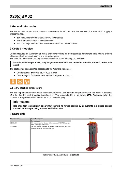
X20(c)BM32 X20(c)BM321 General informationThe bus module serves as the base for all double-width 240 VAC X20 I/O modules. The internal I/O supply is interconnected.•Bus module for double-width 240 VAC I/O modules•The internal I/O supply is interconnected•240 V coding for bus module, electronic module and terminal block2 Coated modulesCoated modules are X20 modules with a protective coating for the electronics component. This coating protects X20c modules from condensation and corrosive gases.The modules' electronics are fully compatible with the corresponding X20 modules.For simplification purposes, only images and module IDs of uncoated modules are used in this data sheet.The coating has been certified according to the following standards:•Condensation: BMW GS 95011-4, 2x 1 cycle•Corrosive gas: EN 60068-2-60, method 4, exposure 21 days2.1 -40°C starting temperatureThe starting temperature describes the minimum permissible ambient temperature when the power is switched off at the time the coated module is switched on. This is permitted to be as low as -40°C. During operation, the conditions as specified in the technical data continue to apply.Information:It is important to absolutely ensure that there is no forced cooling by air currents in a closed control cabinet, for example using a fan or ventilation slots.3 Order dataTable 1: X20BM32, X20cBM32 - Order dataX20(c)BM324 Technical dataTable 2: X20BM32, X20cBM32 - Technical dataX20(c)BM32 5 Voltage routing。

X20 系统用户手册Version: 2.00 (Feb 2008) Model number: MAX20-CHI第一章系统特性在X20系统的基础上, 贝加莱正在制订新的自动化标准。
贝加莱企业文化的核心之一便是完美自动化,也就是"Perfection in Automation"。
这是贝加莱在多年的实践中,在从全世界各个行业,各个领域客户的反馈中,在体会到自动化的真正内涵中形成的一种企业文化。
X20系统便是在此基础上应运而生,它为机械、制造业等各个行业提供了更简单,更经济,更安全的新的解决方案。
一、3 x 1结构X20系统由三部分组成:背板,电气模块,端子排。
这种模块特性使其具有以下一些优点:(1)、不受固定底板的限制;现在很多厂家的PLC都必须带有固定模块数的底板,而X20系统的背板可以免工具的安装在导轨上,并无数量限制(2)、可以将端子排从模块上拔下来接线,接好后再插到模块上,避免了对模块的损坏,接线也是不需要工具的。
(3)、支持热插拔功能二、分布式背板X20系统背板采用X2X总线传输,传输速率为12兆,不受固定底板数量限制,直接可将模块安装在导轨上所有的模块都连接在一个统一的背板(X2X Link)上,可以直接连X20模块,X67模块及阀导。
模块间最大的距离可以达到100米。
三、基于PC的技术X20采用了赛杨处理器,任务周期可以达到200us,指令周期可以达到0.01us,大容量的RAM使得用户不需要担心内存的不够用,程序存储采用CF卡,最大可扩展到8G.四、可选的风扇设计正常情况下,贝加莱PCC是无风扇运行的,但为了保证在一些恶劣环境下不影响CPU的运行,X20也增加了风扇设计,即在一些环境恶劣的情况下,用户也可以选择安装风扇。
五、集成了阀导控制随着XV系统的发展,使得可以对其进行直接的,独立于厂商的阀导控制。
一个完整的数字输出模块类似于一个常用的DSUB连接器。
XV允许客户选择任何厂商制造的阀导来组成系统。
贝加莱PLC-X20操作指南2简介本操作指南旨在为您提供贝加莱PLC-X20的详细使用说明。
PLC-X20是一款性能卓越的可编程逻辑控制器,适用于各种自动化控制应用。
在阅读本指南之前,建议您先熟悉PLC-X20的基本组成和功能。
操作步骤1. 启动与登录1. 打开PLC-X20的电源,等待设备自检完成后,按下设备上的“启动”按钮。
2. 设备启动后,通过串口或网络连接至PLC-X20。
3. 在连接成功后,输入用户名和密码登录PLC-X20的操作系统。
2. 项目浏览器1. 登录成功后,进入项目浏览器。
项目浏览器展示了当前设备上的所有项目,包括已创建的程序、数据块、监视画面等。
2. 通过项目浏览器,您可以创建新项目、打开现有项目、删除项目等。
3. 创建与编辑程序1. 在项目浏览器中,右键点击“程序”目录,选择“新建”→“程序”。
2. 输入程序名称,点击“确定”创建新程序。
3. 双击已创建的程序,进入程序编辑界面。
4. 在程序编辑界面,您可以编写梯形图、功能块图、指令表等程序代码。
5. 编写完成后,点击“保存”按钮保存程序。
4. 配置输入/输出1. 在项目浏览器中,右键点击“输入/输出”目录,选择“配置”。
2. 在输入/输出配置界面,您可以为每个输入/输出通道分配信号类型、地址等参数。
3. 配置完成后,点击“确定”保存设置。
5. 数据块操作1. 在项目浏览器中,右键点击“数据块”目录,选择“新建”→“数据块”。
2. 输入数据块名称,选择数据类型和大小,点击“确定”创建数据块。
3. 双击已创建的数据块,进入数据块编辑界面。
4. 在数据块编辑界面,您可以进行数据的写入、读取等操作。
6. 监视与控制1. 在项目浏览器中,右键点击“监视”目录,选择“新建”→“监视画面”。
2. 输入监视画面名称,选择要监视的变量,点击“确定”创建监视画面。
3. 双击已创建的监视画面,进入监视界面。
4. 在监视界面,您可以实时查看变量的当前值,并对设备进行远程控制。

贝加莱PLC-X20操作指南21. 简介贝加莱PLC-X20是一款功能强大的设备,本操作指南将介绍如何正确操作该设备以实现最佳效果。
2. 准备工作在操作贝加莱PLC-X20之前,请确保已完成以下准备工作:- 确认设备已连接到电源,并处于正常工作状态。
- 确认设备已连接到计算机或控制台,以便进行操作和监控。
3. 操作步骤3.1. 开机按下设备的电源按钮,等待设备启动。
3.2. 导航菜单在设备启动后,您将看到一个导航菜单。
使用方向键选择您要执行的操作,并按下确认键。
3.3. 功能选择在导航菜单中,选择您想要使用的功能。
根据您的需求,可以选择不同的功能,例如数据输入、数据输出、设置等。
3.4. 数据输入如果您选择了数据输入功能,请按照屏幕上的提示输入所需的数据。
确保输入准确无误,并按下确认键保存数据。
3.5. 数据输出如果您选择了数据输出功能,请按照屏幕上的提示选择要输出的数据。
根据需要,您可以选择输出到计算机、打印机或其他外部设备。
3.6. 设置如果您选择了设置功能,请按照屏幕上的提示进行相应设置。
根据您的需求,您可以调整设备的参数、设置报警功能等。
3.7. 关机在完成操作后,选择关机功能并按下确认键,等待设备完全关闭后,再断开电源。
4. 注意事项在操作贝加莱PLC-X20时,请注意以下事项:- 请仔细阅读设备的用户手册,了解设备的功能和操作方法。
- 不要在设备工作时拔插连接线,以免损坏设备或导致数据丢失。
- 如果遇到操作问题或设备故障,请及时联系售后服务部门进行处理。
5. 总结本操作指南介绍了贝加莱PLC-X20的基本操作步骤,以及注意事项。
请按照指南操作设备,以确保设备的正常运行和使用效果。
(800字以上)。
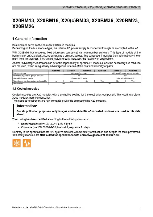
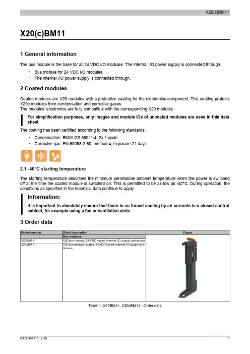
X20BM13, X20BM16, X20(c)BM33, X20BM36, X20BM23, X20BM261 General informationBus modules serve as the basis for all SafeIO modules.Depending on the bus module type, the internal I/O power supply is connected through or interrupted to the left. With X20BMx6 bus modules, fixed addresses can be set via node number switches. This type of module at the beginning of an X20 block always generates a unique address. The subsequent modules then automatically incre-ment from this address. This simple feature greatly increases the flexibility of applications.Another advantage: Addresses can be set independently of specific I/O modules; only the necessary bus modules are required, which is logistically advantageous in terms of the cost and diversity of parts.1.1 Coated modulesCoated modules are X20 modules with a protective coating for the electronics component. This coating protects X20c modules from condensation.The modules' electronics are fully compatible with the corresponding X20 modules.Information:For simplification purposes, only images and module IDs of uncoated modules are used in this data sheet.The coating has been certified according to the following standards:•Condensation: BMW GS 95011-4, 2x 1 cycle•Corrosive gas: EN 60068-2-60, Method 4, exposure 21 daysContrary to the specifications for X20 system modules without safety certification and despite the tests performed, X20 safety modules are NOT suited for applications with corrosive gases (EN 60068-2-60)!2 Order dataX20BM36X20BM26 X20BM13X20BM16X20BM33X20BM23Short descriptionBus modulesX20 bus module, for X20 SafeIO modules, internal I/O power supply continuous, single-widthX20 bus module, for X20 SafeIO modules, with node number switch, internal I/O power supplycontinuous, single-widthX20 bus module, for X20 SafeIO modules, internal I/O power supply continuousX20 bus module, coated, for X20 SafeIO modules, internal I/O power supply continuousX20 bus module, for X20 SafeIO modules, with node number switch, internal I/O power supplycontinuousX20 power supply bus module, for X20 SafeIO power supply modules, internal I/O power supplyinterrupted to the leftX20 power supply bus module, for X20 SafeIO power supply modules, with node number switch,internal I/O power supply interrupted to the leftTable 1: X20BM13, X20BM16, X20BM33, X20cBM33, X20BM36, X20BM23, X20BM26 - Order data3 Technical dataTable 2: X20BM13, X20BM16, X20BM33, X20cBM33, X20BM36, X20BM23, X20BM26 - Technical data4 Voltage routingGND+24 VDC Figure 1: X20BM2x - Voltage routingGND +24 VDCGND+24 VDC Figure 2: X20BM1x / X20BM3x - Voltage routingVoltage routing identificationA symbol is printed on the locking lever on bus modules interrupted to the left. This makes it clear from the outsideof a fully assembled X20 system that bus modules interrupted to the left are used in this slot.Figure 3: X20BM2x - Voltage routing identification5 Manual node number assignment in the X20 safe I/O systemWith the X20 safety bus modules X20BM16, X20BM26 and X20BM36, permanent addresses can be set using node number switches. One of these modules placed at the beginning of an X20 safety block always creates a unique address. The subsequent module addresses are assigned automatically in ascending order starting with this address. This simple feature greatly increases the flexibility of applications.Another advantage: Addresses can be set independently of which specific I/O modules are used. All that is required are the respective bus modules. This provides logistical advantages with respect to cost and the variety of parts.5.1 Node number switchesx16x1Figure 4: X20BMx6 - Node number switchesThe X2X Link address of the module is set using the node number switches (0x01 to 0xFD).Setting node number 0x00 causes the X2X Link address to be assigned automatically.Node number switch identificationSymbols are printed on the locking lever of bus modules with node number switches. This provides a way to see from outside that the X20 system mounted in this slot is using node number switches.Figure 5: X20BMx6 - Node number switch identification6 Version historyTable 3: Version history7 EC declaration of conformityThis document was originally written in the German language. The German edition therefore represents the original documentation in accordance with the 2006/42/EC Machinery Directive. Documents in other languages are to be interpreted as translations of the original documentation.Product manufacturer:B&R Industrial Automation GmbHB&R Strasse 15142 EggelsbergAustriaTelephone: +43 7748 6586-0Fax: +43 7748 6586-26************************The place of jurisdiction, in accordance with article 17 of the European Convention on Courts of Jurisdiction and Enforcement, is A-4910Ried im Innkreis, Austria, commercial register court: Ried im Innkreis, AustriaCommercial register number: FN 111651 v.The place of fulfillment in accordance with article 5 of the European Convention on Courts of Jurisdiction and Enforcement is A-5142 Eggelsberg, AustriaVATIN: ATU62367156The EC declarations of conformity for B&R products can be downloaded from the B&R website .。
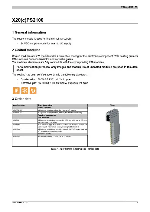
X20(c)PS21001 General informationThe supply module is used for the internal I/O supply.•24 VDC supply module for internal I/O supply2 Coated modulesCoated modules are X20 modules with a protective coating for the electronics component. This coating protects X20c modules from condensation and corrosive gases.The modules' electronics are fully compatible with the corresponding X20 modules.For simplification purposes, only images and module IDs of uncoated modules are used in this data sheet.The coating has been certified according to the following standards:•Condensation: BMW GS 95011-4, 2x 1 cycle•Corrosive gas: EN 60068-2-60, Method 4, Exposure 21 days3 Order dataTable 1: X20PS2100, X20cPS2100 - Order data4 Technical dataTable 2: X20PS2100, X20cPS2100 - Technical data1)The specified values are maximum values. The exact calculation is also available for download as a data sheet with the other module documentation onthe B&R website.2)Ta min.: 0°CTa max.: See environmental conditions5 LED status indicatorsFor a description of the various operating modes, see the section "re LEDs" in chapter 2 "System characteristics"of the X20 system user's manual.6 PinoutX 20 P S 2100r e7 Connection examplePS8 Shutting the potential group down safelyIn safety-related applications, it must be guaranteed that the potential group is safely shutdown in order to achieve category 4 shutdown in accordance with ISO 13849. An X20PS2100 (rev.F0 or higher) or X20PS2110 (rev.C0 or higher) supply module must be used to do this.Important notes on "Safe shutdown" are listed in the X20 system user's manual, section"Mechanical and electrical configuration", section "Safe shutdown". The user's manual is available in the Downloads section of the B&R website ( ).9 Register description9.1 General data pointsIn addition to the registers listed in the register description, the module also has other more general data points. These registers are not specific to the module but contain general information such as serial number and hardware version.These general data points are listed in the "General data points" section of chapter 4 "X20 system modules" in the X20 system user's manual.9.2 Function model 0 - Standard9.3 Function model 254 - Bus controller1)The offset specifies the position of the register within the CAN object.9.3.1 CAN I/O bus controllerThe module occupies 1 analog logical slot on CAN-I/O.9.4 Module statusName:Module statusThe following module supply voltages are monitored in this register:Bus supply voltage: A bus supply voltage of <4.7V is displayed as a warning.24 VDC I/O supply voltage:An I/O supply voltage of <20.4 V is displayed as a warning.Bit structure:9.5 Bus supply voltageName:SupplyVoltageThis register displays the bus supply voltage measured at a resolution of 0.1 V.9.6 Minimum cycle timeThe minimum cycle time defines how far the bus cycle can be reduced without communication errors occurring. It should be noted that very fast cycles decrease the idle time available for handling monitoring, diagnostics and acyclic commands.9.7 Minimum I/O update timeThe minimum I/O update time defines how far the bus cycle can be reduced while still allowing an I/O update to take place in each cycle.。
X20 系统用户手册Version: (Feb 2008) Model number: MAX20-CHI第一章系统特性在X20系统的基础上, 贝加莱正在制订新的自动化标准。
贝加莱企业文化的核心之一便是完美自动化,也就是"Perfection in Automation"。
这是贝加莱在多年的实践中,在从全世界各个行业,各个领域客户的反馈中,在体会到自动化的真正内涵中形成的一种企业文化。
X20系统便是在此基础上应运而生,它为机械、制造业等各个行业提供了更简单,更经济,更安全的新的解决方案。
一、3 x 1结构X20系统由三部分组成:背板,电气模块,端子排。
这种模块特性使其具有以下一些优点:(1)、不受固定底板的限制;现在很多厂家的PLC都必须带有固定模块数的底板,而X20系统的背板可以免工具的安装在导轨上,并无数量限制(2)、可以将端子排从模块上拔下来接线,接好后再插到模块上,避免了对模块的损坏,接线也是不需要工具的。
(3)、支持热插拔功能二、分布式背板X20系统背板采用X2X总线传输,传输速率为12兆,不受固定底板数量限制,直接可将模块安装在导轨上所有的模块都连接在一个统一的背板(X2X Link)上,可以直接连X20模块,X67模块及阀导。
模块间最大的距离可以达到100米。
三、基于PC的技术X20采用了赛杨处理器,任务周期可以达到200us,指令周期可以达到,大容量的RAM使得用户不需要担心内存的不够用,程序存储采用CF卡,最大可扩展到8G.四、可选的风扇设计正常情况下,贝加莱PCC是无风扇运行的,但为了保证在一些恶劣环境下不影响CPU的运行,X20也增加了风扇设计,即在一些环境恶劣的情况下,用户也可以选择安装风扇。
五、集成了阀导控制随着XV系统的发展,使得可以对其进行直接的,独立于厂商的阀导控制。
一个完整的数字输出模块类似于一个常用的DSUB连接器。
XV允许客户选择任何厂商制造的阀导来组成系统。
X20(c)AT64021 General informationThe module is equipped with 6 inputs for J, K, N, S, B and R thermocouple sensors. The module has an integrated terminal temperature compensation.•6 inputs for thermocouples•For sensor types J, K, N, S, B, R•Additional direct raw value measurement•Integrated terminal temperature compensation•Configurable filter time2 Coated modulesCoated modules are X20 modules with a protective coating for the electronics component. This coating protects X20c modules from condensation and corrosive gases.The modules' electronics are fully compatible with the corresponding X20 modules.For simplification purposes, only images and module IDs of uncoated modules are used in this data sheet.The coating has been certified according to the following standards:•Condensation: BMW GS 95011-4, 2x 1 cycle•Corrosive gas: EN 60068-2-60, Method 4, Exposure 21 days3 Order dataTable 1: X20AT6402, X20cAT6402 - Order data4 Technical dataTable 2: X20AT6402, X20cAT6402 - Technical dataTable 2: X20AT6402, X20cAT6402 - Technical data 1)Ta min.: 0°CTa max.: See environmental conditions2)Based on the entire measurement range without consideration of the cold junction measurement error3)Based on the current measured value.4)Based on the entire measurement range.5 LED status indicatorsFor a description of the various operating modes, see the section "re LEDs" in chapter 2 "System characteristics"of the X20 system user's manual.6 Pinout1X 20 A T 640223456r e 7 Connection exampleAT8 Input circuit diagram9 Ceramic heating element with integrated thermo elementsWe recommend connecting the minus input of the thermo element to the minus input of the supply feed module. This prevents potential measurement errors caused by ripple voltage effects in the measurement signal.10 External cold junctionGeneral informationAn external cold junction temperature value can be predefined for the module for measurement value correction. This makes it possible to set up an external cold junction. The same external cold junction temperature is used for measurement value correction on all channels.An external cold junction makes sense in the following applications and situations:•Large distances between the controller and measurement point•To increase precisionTo bridge large distancesSetting up an external cold junction is recommended when there are large distances between the controller and the measurement point. The thermocouple voltage is routed from the external cold junction to the terminal on the X20AT6402 via copper wires. The temperature measured at the external cold junction (e.g. with PT100 -X20AT4222) is stored in the I/O area of the X20AT6402 module. The X20AT6402 uses the measured voltage andthe cold junction temperature to internally calculate the needed thermocouple temperature.Increased precisionSetting up an external cold junction is recommended to increase precision. The external cold junction is set up asdescribed above. The installation of an external cold junction is especially helpful in the following cases:•A module consuming more power than 1 W is connected in addition to the X20AT6402.•No modules but the X20AT6402 are connected•With strongly fluctuating ambient conditions (draft, temperature)11 Register description11.1 General data pointsIn addition to the registers listed in the register description, the module also has other more general data points. These registers are not specific to the module but contain general information such as serial number and hardware version.These general data points are listed in the "General data points" section of chapter 4 "X20 system modules" in the X20 system user's manual.11.2 Function model 0 - default11.3 Function model 1 - External cold junction temperature11.4 Function model 254 - Bus controller1)The offset specifies the position of the register within the CAN object.11.5 General information11.5.1 Raw value measurementIf a sensor type other than J, K, N, S, B or R is used, the terminal temperature must be measured on at least one input. Based on this value, the user must then implement terminal temperature compensation.11.5.2 TimingThe timing for acquiring measurement values is determined by the converter hardware. All enabled inputs are converted during each conversion cycle. In addition, the terminal temperature is measured (not in function model 1). Any inputs that are not needed can be switched off, which reduces the I/O update time. Inputs can also be only switched off temporarily. Measuring the terminal temperature is switched off in function model 1.11.5.3 Conversion timeThe conversion time depends on the number of channels and the function model. For the formulas listed in the table, "n" corresponds to the number of channels that are switched on.ExamplesInputs are filtered using a 50 Hz filter.11.6 Configuration11.6.1 Input filter and ambient conditionsName:ConfigOutput01This register configures input filters and ambient conditions.Input filterThe filter time for all analog inputs is defined using the input filter parameter.Environmental conditionsAmbient conditions are set in order to adjust the internal terminal temperature characteristic curve to the type and amount of generated heat dissipated to the module.This selection is based on the power consumption of the modules connected immediately to the left and right on the X2X Link. Power consumption values can also be found in the technical data for the corresponding module. The higher value is used for the configuration.Bit structure:11.6.2 Sensor typeName:ConfigOutput02This module is designed for a wide range of sensor types. The sensor type must be configured because of the different alignment values.11.6.3 Channel disablingName:ConfigOutput03By default, all channels are switched on. To save time, individual channels can be switched off (see "Conversion time" on page 8).Bit structure:X20(c)AT6402 11.7 Communication11.7.1 Analog inputsName:Temperature01 to Temperature06Analog input value depending on the configured sensor type:In order for the user to always be supplied with a defined output value, the following must be taken into consid-eration:•Up to the first conversion, 0x8000 is output.•After switching the sensor type, 0x8000 is output until the first conversion.•If the input is not switched on, 0x8000 is output.11.7.2 I/O cycle counterName:IOCycleCounterThe cyclic counter increases after all input data has been updated.11.7.3 Input statusThe module's inputs are monitored. A change in the monitoring status generates an error message.In addition to the status info, the error type also sets the analog value as follows:11.7.3.1 Status of inputs 1 to 4Name:StatusInput01Bit structure:X20(c)AT640211.7.3.2 Status of inputs 5 to 6Name:StatusInput02Bit structure:11.7.4 Reads the internal cold junction temperatureName:CompensationTemperatureThe internal cold junction temperature is stored in this register.11.7.5 Defines the external cold junction temperatureName:ExternalCompensationTemperatureThe external cold junction temperature is defined in this register.11.8 Minimum cycle timeThe minimum cycle time defines how far the bus cycle can be reduced without communication errors occurring. It should be noted that very fast cycles decrease the idle time available for handling monitoring, diagnostics and acyclic commands.11.9 Minimum I/O update timeThe minimum I/O update time defines how far the bus cycle can be reduced while still allowing an I/O update to take place in each cycle.For the formulas listed in the table, 'n' corresponds to the number of channels that are switched on.。
1产品技术描述现场层设备现场控制器(贝加莱)本方案采用贝加莱性价比极高的X20 Compact CPU做现场控制器,其主要性能参数如下1.100KB SRAM2.512kB FPROM,无需电池缓冲3.实时时钟4.1个标准RS232接口5.1个100Base-T工业以太网接口6.指令周期0.8 μs7.最快任务周期: 2ms8.状态LED灯诊断指示分时多任务操作系统处理器的能力分在多个任务中,多个任务同时处理数据。
1.并行处理几个控制任务;2.确定多个任务的处理时间;3.监控任务时灵活设定循环时间;4.每个任务级别分配一致的I/O映像。
I/O模块本方案采用的I/O模块性能如下:1.模块化设计电气端子可拆卸,提供了施工/维护的方便性及测试状态等指示。
工业级抗干扰,安全特性符合C-UL-US、CSA、CE、GOST-R等认证。
2.电子模件和电源模件都采用防尘、防潮、防静电、防电磁干扰,适合远程就地安装,抵御恶劣工作环境影响,生命期内免维护。
3.I/O模件通道都采用了先进的电气隔离技术(光电隔离、继电器隔离、线性放大器隔离),抗干扰能力强。
I/O通道设计安装有PTC电子保险装臵,当遇强电冲击或误接强电入I/O通道时,通道立即被阻塞保护,强电去除后,通道功能逐渐恢复。
4.采用全分散型智能I/O测控模件支持控制器和I/O模件全部前臵的远程控制站安装方式和智能I/O子系统前臵的远程I/O站安装方式。
具体模块类型特性:DI输入(X20DI9371)(贝加莱)1.数字量输入:12路(漏式)2.输入额定电压:24 VDC3.输入延时: 0~25ms4.状态显示:每个通道的输入状态可读DO输出(X20DO4322)(贝加莱)1.数字量输出:4路晶体管(源式接法)2.输出额定电压: 24VDC3.额定电流:< 0.5A4.状态显示:每个通道的输出状态可读DO输出(X20DO9322)(贝加莱)5.数字量输出:12路晶体管(源式接法)6.输出额定电压: 24VDC7.额定电流:< 0.5A8.状态显示:每个通道的输出状态可读AI输入(X20AI4622)(贝加莱)1. 4路输入:4 20mA2.转换时间:所有输入转换时间400μs3.数字量转换分辩率:12BIT4.基本精确度:输入范围的+/-0.1%5.输出格式:INT6.负载:400Ω7.输入隔离:通道与PCC隔离模块端子排(贝加莱)1. 保护:IP202.湿度:5-95%(非冷凝)3.触点阻抗:≤2mΩ4.额定电压:300V5.额定电流:5A/触点6.电缆类型:仅用铜线7.端子类型:弹簧夹设计X20PS9500电源模块(贝加莱)1.保护:IP202.电压范围:18VDC-30VDC3.熔断丝:集成4.过载措施:短路保护,过载保护,反极性保护5.认证:CE,C-UL-US,GOST-R6.湿度:5-95%(无冷凝)7.操作/贮藏温度:0℃- +60℃/-20℃- +70℃人机界面♣不只是显示Power Panel 100嵌入式系列产品由一系列显示终端组成,这些显示终端均可与其它Power Panel终端、工业PC、控制器或其它高级计算机系统相连。
X20IF10721 General informationThe X20IF1072 interface module can be used to expand the X20 CPU for specific applications. It is equipped with a CAN bus interface.•CAN bus connection•Integrated terminating resistor2 Order dataTable 1: X20IF1072 - Order data3 Technical dataTable 2: X20IF1072 - Technical data 1)This CAN bus interface can be configured as a CANopen master in Automation Studio 3.0 and higher.4 LED status indicatorsTable 3: LED status indicators5 Operating and connection elementsFigure 1: Operating and connection elements6 Node number switchFigure 2: Number switches for node numbers and transfer rates The node number for the interface is set with the two hex switches.7 CAN bus interfaceThe interface is a 5-pin multipoint plug. The 0TB2105 terminal block must be ordered separately.Table 4: Pinout8 Terminating resistorFigure 3: Terminating resistorA terminating resistor is integrated in the interface module. It can be turned on and off with a switch on the bottom of the housing. An active terminating resistor is indicated by the "TERM" LED.9 FirmwareThis module comes with preinstalled firmware. The firmware is a component of Automation Studio. The module is automatically updated to this version.To update the firmware included in Automation Studio, the hardware must be upgraded (see "Project manage-ment" / "Automation Studio upgrade" in the help system).。