日本三丰轮廓粗糙度仪软件FORMTRACEPAK
- 格式:pdf
- 大小:1.92 MB
- 文档页数:8
Mitutoyo’s newly designed detector arm lowers workpiece interference while expanding the measurement range in the Z1 axis (detector).• When using the SPH-71 one-sided cut stylus Continuous top-bottom measurement functionUpper and lower surfaces can be measured continuously by using Mitutoyo’s double-sided conical stylus.This continuous measurement data can be used to facilitate analysis of features that were difficult to measure before, such as the effective diameter of an internal screw-thread.Detector measurement range expanded by 10 mm50mm10 mm•mm19 mm•One-touch arm attachment (Patent pending in Japan)The arm mount uses a magnetic joint for quick and easy arm replacement. The mount also includes a safety mechanism.Screw fixing• SV-C4100 (Conventional product )• SV-C4500Variable measuring force functionThe measuring force can be varied in 5 steps by using the software provided (FORMTRACEPAK ), eliminating the need to adjust the measuring force by switching weights or through positionaladjustment.The SV-C4500 Series can also maintain the specified measuring force even when tilted.Measuringforce •Removable arm Arm mountLower direction measurement(Bottom surface)Top and bottommeasurement switched by softwareUpper direction measurement(Top surface)Continuous top-bottom measurement allows hassle-free one-step calibration(Patent pending in Japan)The one-step calibration kit supplied with the SV-C4500 Series has been upgraded to enable easy calibration of the double-endedconical stylus featuring a contact on both the top and the bottom.Precise work such as calibrating the Z1-axis gain, symmetry, and stylus radius can now be carried out in a single operation. • Calibration kit for SV-C4500 SeriesContour Measuring FunctionsHybrid measuring instrument forsurface roughness and contour measurementSupporting International StandardsCompliant with JIS '82/'94/'01, ISO, ANSI, DIN, VDA, and other international surface roughness standards.We offer a product lineup of surface roughness detectors with different measuring forcesStandard detectors can be selected (as listed below) to conform to the international standard required.0.75mN (tip angle 60°; tip radius 2µm)4mN (tip angle 90°; tip radius 5µm)Reduction of measuring time and operator’s fatigueIn addition to high speed movement of main unit, reduction of setting time and operator’s fatigue can be achieved by using Auto-leveling Table (option), which allows automatic leveling for a measuring face.Fast traverse improves measurement efficiencyX axis (drive unit) : 80mm/s (MAX)Z2 axis (column) : 30mm/s (MAX)Auto stop feature assures safety even during high-speed movementThe detector includes a safety mechanism (auto stop upon collision) to assure measurement safety even during high-speed movement. If the arm is removed or shifts during measurement, the safety mechanism is triggered and stops the machine.Direction of collision that may cause the safety device to be triggered• Detector for contour measuring• Detector for surface roughness measuringSV-C3200S4SV-C4500S4Z2 axis (column)X axis (drive unit)The total measurement time can be shortened by speeding up the traverse movements.Remote-control unit enables safe, easy & fast measurementThe remote-control unit lets you move quickly from positioning to measurement. The unit also features an emergency stop switch and speed control knob for added safety while the machine is moving at high speeds.Incorporation of an ABS scale in the Z2 axis eliminates the need for wearisome origin point re-setting conventionally required for every step of repeated measurements over stepped or multiple sections.All detector and drive unit cables are housed inside the main unit to eliminate any risk of abrasion and guarantee trouble free, high-speed operation.New Remote Control BoxSurface Roughness Measuring FunctionsCommon specificationsSV-C4500SV-C3200• Contour analysis functionUpper and lower surfaces can be measured continuously by usingMitutoyo’s double-sided conical stylus.This continuous measurement data can be used to facilitate analy-sis of features that were difficult to measure before, such as the effective diameter of an internal screw-thread.Contour Analysis Software: FORMTRACEPAKNote: Please refer to the FORMTRACEPAK catalog (2021) for more details.• Surface Roughness analysis function FORMTRACEPAK can perform surface roughness analyses that conform to various standards such as ISO, JIS ANSI, and VDA. For comparing the measurement values with the tolerance limits, you can use the 16% rule or the maximum value rule. Furthermore, since FORMTRACEPAK comes with parameter calculation functions as well as a rich set of graphic analysis functions, it can be widely utilized for everything from routine quality control to R&D applica-tions. It also includes many other func-tions, such as the function for elimi-nating (compensat-ing) shapes, such as slopes and R-surface, and a data deletion function.• Contour-tolerancing function as a standard feature • Design value generation function • Data combination function • Simple pitch calculation function• Microscopic contour analysis function • Simple input using drawing symbols • Multiple-point measurement function• Analysis function using multiple-point measurement • Reference length dialog box• Analysis condition modification with a preview function • R-surface automatic measurement functionContour MeasuringSurface Roughness MeasuringIntegrated layoutYou can use simple operations to lay out graphics obtained from measurements as well as measurement results for surface roughness, contour, and roundness on a single page.Furthermore, since the program now allows you to specify a saved file and paste it, you can easily paste results from multiple files.Note: the optional ROUNDPAK roundness/cylindricity analysis program is required. (Ver. 7 or higher)• Element information bar This bar displays the attribute values of the pasted items, allowing you to easily check the contents of the pasted measurement data files.• System layout printing By simply selecting the items to be output, you can automatically lay out the page to be printed.Use this feature when you wish to simplify the printing task.Using the mouse to drag and drop the analysis content displayed in the element insertion bar, you can paste it onto the layout. From the contour analysis result, you can also select the analysis result for a circle or line alone and paste it in position.• Saving the result as a web page Since you can save the result in html or mhtml format, which can be displayed using Internet Explorer or Microsoft Word, you can check the result even on a PC in which no layout-editing program is installed.• Report creation functionYou can freely assemble measurement results/conditions/graphics as well as comments/circles/lines/arrows, and print them out in a measure-ment result report. Furthermore, since you can paste bitmap files, you can also add a workpiece image or company logo to the layout.You can also save the created layout and use it again later for similar measurements.*Not supporting Y-axis measurements*Used with 178-096 for 3D surface roughness measurementsOptional Accessories for Automatic MeasurementA Y-axis table for positioning and capable of 3D surface roughness measurement when used with FORMTRACEPAK-Pro or MCubeMap.For efficient measurement in the axial/transverse directions. When measuring a cylindrical workpiece, automatic alignment can be performed in combination with the Y-axis table.*q 1-axis mounting plate (12AAE630) is required when directly installing on the base of the SV-C3200/4500.This is a stage that performs fully automatic leveling as measurement starts, freeing the user from this troublesome operation. Fully automatic leveling can be done quickly by anyone. In addition, the operation is easy and reliable.You can measure multiple points on a cylindrical workiece and automate front/rear-side measurement.*q 2 -axis mounting plate (12AAE718) is required when directly installing on the base of the SV-C3200/4500.This chuck is useful when measuring small workpieces. You can easily clamp them with its knurled ring.This chuck is suitable for clamping extra-small diameter workpieces (ø1 mm or less), which cannot be retained with the centering chuck.Centering chuck (ring operated): 211-032Micro-chuck: 211-031Y-axis table: 178-097 / 178-096Rotary Table q 1-axis table: 12AAD975*Rotary Table q 2-axis unit: 178-078*Auto-leveling table: 178-087 / 178-077178-077178-087178-097178-096• Desk type vibration isolatorsM anually charged pneumatic type*4• Desk typevibration isolatorsD esk type *4No.12AAK110Monitor arm *5No.12AAK120Side table *5No.12AAL019Automatically charged pneumatic type *4No.178-025Stand for Desktop typeExternal size (W×D×H):640×470×660mmMass: 25kgExample combination: with side table but no monitor arm (tester and PC not included)Example combination: with monitor arm but no side table *6(tester and PC not included)Desk Side table DeskMonitor armOptionsThis table helps make the alignment adjustments required when measuring cylindrical surfaces. The corrections for the pitch angle and the swivel angle are determined from a preliminary measurement and the Digimatic micrometers are adjusted accordingly. A flat-surfaced work-piece can also be leveled with this table.3-axis Adjustment Table: 178-047Table and fixture systemsRotary vise218-003V-block998291Precision vise 178-019Cross-travel table218-001 (mm), 218-011 (inch)Cross-travel table218-041 (mm), 218-051 (inch)V-block with clamp 172-234, 172-378Holder with clamp 176-107Swivel center support 172-197Center support riser 172-143Center support 172-142Leveling table 178-043-1 (mm), 178-053-1 (inch)Digital Leveling table 178-042-1 (mm), 178-052-1 (inch)Leveling table 178-016Leveling table (for D.A.T.)178-048 (mm),178-058 (inch)Calibration stand *212AAG175Calibration stand *112AAM100 Calibration stand *312AAM309*1 Required for calibrating upward measurement of SV-C3200 series.*2 Required for calibrating in bulk by mounting straight arm/small-hole stylus arm without using cross-travel table and Y-axis table.*3 Required for calibrating in bulk by mounting straight arm/eccentric arm/small-hole stylus arm without using cross-travel table and Y-axis table.*4 For models with a product code that ends in S4, S8, H4, or H8. Please contact us directly if you require units for models with a product code that ends in W4/L4 or W8/L8 (large base models).*5 Used together with vibration isolator (No.12AAK110).*6 User to provide a printer rack.* V-block not includedStandard stylus12AAE882 (1µm) *1Double-length for deep hole **2: For downward-facing measurement only.*3 :44.7DetectorsExtension rodsOptional Detector HoldersStyliDetectors / Styli(For Surface Roughness Measuring)14601011.5• 12AAG202 Extension rod 50mm• 12AAG203 Extension rod 100mm* No more than one extension rod can be connected.178-074178-091178-092StyliFor deep groove(10mm)For deep groove *Please contact any Mitutoyo office for more information.Arms / Styli (For Contour Measuring)StyliArms*1 Standard accessory*2 Stylus for SV-C4500 series*3 One-sided cut stylus SPH-71 (standard accessory) mounting•Straight arm AB-31*2 Standard accessory of SV-C4500 series *3 Standard accessory of SV-C3200 series*4 Styli SPH-21, 22, and 23 for SV-C3100/4100 series are not available.Tip angle: 20ºEdge width: 3mm Tip radius: 25µm Carbide-tippedOne-sided cut stylusTip angle: 12ºTip radius: 25µm Carbide-tipped Intersecting cut stylusTip angle: 20ºTip radius: 25µm Carbide-tippedKnife edge stylusBall stylusBall dia: 1mm Carbide-tippedCone stylusTip angle: 30º (SPH-79: 50º)Tip radius: 25µmSapphire, Carbide-tipped (SPH-79:Diamond tipped)Cone stylusTip angle: 20ºTip radius: 25µm Carbide-tippedSmall hole stylus Carbide-tippedSmall hole stylus SPH-42Carbide-tippedSmall hole stylus SPH-43Double-sided conical stylus Tip angle: 30ºTip radius: 25µm Carbide-tipped●of the tipof the tip of the tipDimensionsX-axis (drive unit) measuring range : 100mm TYPE (S4/H4/W4/L4)X-axis (drive unit) measuring range : 200mm TYPE (S8/H8/W8/L8)Unit: mm(Common for all models)Mitutoyo America Corporation One Number to Serve You Better1-888-MITUTOYO (1-888-648-8869) M3 Solution Centers: Aurora, Illinois (Headquarters) Boston, Massachusetts Huntersville, North Carolina Mason, OhioPlymouth, MichiganCity of Industry, California Birmingham, Alabama Renton, Washington Houston, Texas1.5M 0716-01 • Printed in USA • July 2016Find additional product literatureand our product catalogNote: All information regarding our products, and in particular the illustrations, drawings,dimensional and performance data contained in this printed matter as well as other technicaldata are to be regarded as approxim ate average values. We therefore reserve the rightto m ake changes to the corresponding designs. The stated standards, sim ilar technicalregulations, descriptions and illustrations of the products were valid at the time of printing.In addition, the latest applicable version of our General Trading Conditions will apply. Onlyquotations submitted by ourselves may be regarded as definitive. Specifications are subjectto change without notice.Mitutoyo products are subject to US Export Administration Regulations (EAR). Re-export orrelocation of our products may require prior approval by an appropriate governing authority.Trademarks and RegistrationsDesignations used by companies to distinguish their products are often claimed as trademarks.In all instances where Mitutoyo America Corporation is aware of a claim, the product namesappear in initial capital or all capital letters. The appropriate companies should be contactedfor more complete trademark and registration information.© 2016 Mitutoyo America CorporationCoordinate Measuring MachinesVision Measuring SystemsForm MeasurementOptical MeasuringSensor SystemsTest Equipmentand SeismometersSmall Tool Instrumentsand Data ManagementDigital Scale and DRO Systems。
2Requirement1High-accuracy measurements with a hand-held testerA wide-range, high-resolution detector and an straight drive unit provide superior high-accuracy measurement in its class.<Detector>Measuring range: 800µmResolution: 0.000125µm (at 8µm range)<Drive unit>Straightness/traverse lengthSJ-401: 0.3µm/25mm SJ-402: 0.5µm/50mmRequirement5Advanced data processing with an extended analyzing programThe SJ-400 series allows data processing that is identical to that in the high-end class. These data analysis and report creation capabilities can be achieved with this system using the surface roughness analyzing program SURFPAK-SJ.Requirement3Measurement of cylinder surfaceroughness even with a compact typeThe skidless measurement and R-surface compensation functions make it possible to evaluate cylinder surface roughness.Requirement2Roughness parameters that conform tointernational standardsThe SJ-400 series performs 36 kinds of roughness measurements that conform to the latest ISO, DIN, and ANSI standards as well as to JIS standards (1994/1982).Now, long-awaited specifications and functions are at hand: compactness,skidless measurement, high-accuracy roughness detection, multi-function, and ease of operation.Revolutionary New Portable Surface Roughness Testers Make Their Debut!SJ-401SJ-402SJ-401Requirement4Measurement/evaluation of stepped features and straightnessUltra-fine steps, straightness and waviness can be measured by switching to the skidless measurement function. The ruler functionenables simpler surface feature evaluation on the LCD monitor.3Surftest SJ-400Calculation Result screen Measured Profile screenRequirement6Confirmation of a measurement results and an assessed profile without printoutUsing the integrated large touch-panel LCD monitor,measurement results and an assessed profile can be clearly displayed.Measurement ApplicationsRuler Analysis screenA variety of accessories•A stylus and a nosepiece can be selected according to the measurement condition. (See page 9 – 11.)Simplified surface feature evaluation with the ruler function•This function determines the coordinate difference between two arbitrary points, such as a step height and a pitch interval.The SJ-400 series employs a detector with exchangeable nosepiece that is interchangeable between skidless measurement and skid measurement. It allows optional evaluation according to measurement conditions.NosepieceRuler function keyRuler keyCoordinate differenceRulerStylusDetectorSurftest SJ-400DAT screen showing the amount to be adjustedThe D.A.T. FunctionThe height-tilt adjustment unit comes as standard for powerful support of the leveling operation at skidless measurement. This unique and convenient function has achieved high-accuracy measurement with ease of operation.Move the micrometer head by this amount.Digimaticmicrometer headLeveling table (for D.A.T.)When using with the stand,the D.A.T. function can work with the optional leveling table.Support for R-surface roughness measurement (skidless measurement)Usually a workpiece with a spherical or cylindrical surfacecannot be evaluated. By eliminating the round surface element with a filter, this function processes this R-surface data as if it was taken from a flat surface.Built-in thermal printerA high-quality, high-speed thermal printer prints out measured results. It can also print a BAC curve or an ADC curve as well as calculated result and assessed profile. These results and profiles can be printed out in landscape format, just as they appear on the LCD. They are presented in an easy-to-understand form.Measurement of a cylindricalsurfaceStatistical processing functionThis function performs statistical processing of multiplemeasurements for one roughness parameter. It is possible to display and print histograms in addition to statistical results (mean, standard deviation, maximum value/minimum value,and acceptance ratio).StatisticalHistogramsSwitchableSurftest SJ-400Calculation Result screen with GO / NG judgment resultAccording to the upper/lower tolerance limits set the GO/NG judgment sign is displayed and the calculation result is highlighted (max. for 3 roughness parameters).Calibration screenThe SJ-400 series is equipped with the Ra calibration and step calibration methods for detector calibration (gain adjustment).In both calibration methods only the reference value described in the precision specimen needs to be entered. No other operation such as volume control is required.and conditionsIt is possible to save the measurement conditions and measured data in the control unit or memory card (optional) and to recall the data from both.Batch printout of the measured data after performing on-site measurement and saving the data will raise measurement efficiency.This function invalidates the key operation on the touch panel.Since only the sheet key operation is valid, there is no chance for error in data, including calibration conditions and measurement conditions.This function samples a displacement of the stylus for the specified time without traversing the detector.It has a wide range of uses such as a simplified vibration meter or a displacement gage incorporated in another system.It is possible to recalculate already measured data for other evaluation by changing the current standard, assessed profile and roughness parameters.This function allows a sampling length to be arbitrarily set in 0.1mm increments (SJ-401: 0.1mm to 25mm, SJ-402: 0.1mm to 50mm). It also allows the SJ-400 series to make both narrow and wide range measurements.Customize functionThis function selects only the necessary parameters forcalculation/display from a variety of roughness parameters. It is also possible to add parameters later for recalculation.Customized screenGO signNG signInvalidatedSURFPAK-SJ SpecificationsEvaluation Curve displayAnalysis graph displayEvaluation condition displayMeasurement condition displayCalculation result display Analysis screenSurftest SJ-400Carrying case is a standard accessory10Detector178-396-2: 0.75mN measuring force, with 12AAC731 standard type stylus (2µm tip radius)178-397: 4mN measuring force, with 12AAB403 standard type stylus (5µm tip radius)Set configuration/Dimensionsø146.83.6146027.2ø8ø142410.42.8DetectorSkid nosepiece (12AAB344)Stylus ø14ø7103.13.61.3Skidless nosepiece (12AAB355)90°0.937.77.644.7ø2.4ø1.25.2A Distinguish colorDetail - A0.60.41.6ø0.690°(S=5/1)Detail - A ø2.415ø1.23.42.41.60.637.744.4ADistinguish color0.41.2ø0.390°(S=5/1)Detail - A ø2.48.9ø0.62.537.71.244.2ADistinguish colorø0.390°Distinguish color0.80.4Detail - A (S=5/1)ø2.437.72.5ø0.68.944.20.8Aø2.487.70.9Ø1.290°94.77.65.2A distinguish color Detail - Aø2.4137.70.97.6144.7ø1.290°5.2ADistinguish colorDetail - Aø14Ø7.2R 403.623.53.56.73.65.621.5 2.8Stylus tip positionø14ø3R 400.61.63.621.5 5.63.623.51.43.515.6ø7.23.8R2Stylus tip positionø14R 403.61.222.321.5ø1.926.73.53.8ø7.2Stylus tip positionø7ø141.33.6421.5103.5Stylus tip positionø14R 405.621.5 3.623.53.53.6ø7.26.87.5Stylus tip position150°Standard type12AAC731 (2µm)*112AAB403 (5µm)12AAB415 (10µm)( ): Tip radiusSmall hole type12AAC732 (2µm)*112AAB404 (5µm)12AAB416 (10µm)( ): Tip radiusExtra small hole type12AAC733 (2µm)*112AAB405 (5µm)12AAB417 (10µm)( ): Tip radiusExtra small hole typeDeep hole type12AAC734 (2µm)*112AAB406 (5µm)12AAB418 (10µm)( ): Tip radius2 x stylus12AAC740 (2µm)12AAB413 (5µm)12AAB425 (10µm)( ): Tip radius3 x stylus12AAC741 (2µm)*112AAB414 (5µm)12AAB426 (10µm)( ): Tip radius12AAB35512AAB34412AAB34512AAB34612AAB347Skidless nosepieceUnit: mmStylusApplicable skid nosepiece*1 Tip angle is 60°11Surftest SJ-400Deep groove type*212AAC735 (2µm)*112AAB409 (5µm)12AAB421 (10µm)( ): Tip radiusExtra deep groove type*212AAC736 (2µm)*112AAB408 (5µm)12AAB420 (10µm)( ): Tip radiusExtra deep groove type*212AAC737 (2µm)*112AAB407 (5µm)12AAB419 (10µm)( ): Tip radiusGear face typeEccentric type*2*1 Tip angle is 60° *2 At using this stylus, measuring force of the detector does not guarantee.12AAB339 (2µm)*112AAB410 (5µm)12AAB422 (10µm)( ): Tip radius12AAC739 (2µm)*112AAB412 (5µm)12AAB424 (10µm)( ): Tip radiusKnife edge type12AAC738 (2µm)*112AAB411 (5µm)12AAB423 (10µm)( ): Tip radiusWE-curve type12AAB33812AAB349StylusApplicable skid nosepiece12AAB35012AAB35112AAB35212AAB34812AAB35312AAB35413ø2.40.9ø1.290°14.237.744.7ADistinguish ColorDetail - A230.9ø2.424.2ø1.290°37.744.7A Detail - ADistinguish color3533.85.2ø1.2A Distinguish colorø2.4Ø2.490°37.745.2Detail - A60°60°7.66.437.743.8ø1.2ø2.4ADistinguish colorDetail - A7.6ø2.4ø1.20.937.744.7Ball ø1.5885.27.6ø2.4ø1.290°37.70.944.7ADistinguish colorDetail - AADetail - A37.70.990°ø0.6Distinguish color457.610ø2.4ø2.4ø14R 4012.80.61.41.43.53.819.5 1.821.54.53.6109ø7.2Stylus tip positionR24.4ø14ø7.2R 403.623.51.413.421.5 5.63.6 2.8103.5Stylus tip positionR2ø14ø7.2(8.4)3.63.819.51.821.53.513.4 2.55910Stylus tip positionø1.5ø14R 4017.9Ø7.23.521.553313.64.513.49 1.4511.610R210Stylus tip positionø14R 403.53.819.5 1.821.522.80.61.42720Ø7.29Stylus tip positionR21.44.4ø14R 401.43.50.521.5ø7.219.72.36.14.50.61.43.62.3R2Stylus tip position4.4ø14R 4021.56.7ø7.25.63.63.63.523.52.8Stylus tip positionFlat Unit: mm12Order No.178-019Mounting method Two-sliding- jaw Clamp opening 36mm/1.42”Clamp width 44mm/1.73”Clamp depth 16mm/.63”Height38mm/1.50”Stand, TablesManual column standColumn travel: 200mmDimensions: 370x200x740mm Mass: 13kg178-009178-042-1 (mm)178-052-1 (inch/mm)178-049 (mm)178-059 (inch/mm)XY leveling tables178-019Precision vise•Can be used with the XY leveling table.74313178-043-1 (mm)178-053-1 (inch/mm)Order No.178-042-1,178-052-1178-043-1,178-053-1178-049,178-059Table size130 x 100mm/5.12” x 3.94”Maximum loading weight 15KgInclination angle±1.5˚—Horizontal rotating angle ±3˚—X, Y axis displacement ±12.5mm/.49”±12.5mm/.49”±12.5mm/.49”Min. reading0.001mm/.00005”*0.001mm/.001”*0.001mm/.00005”*of the micrometer head Dimension 262 x 233 x 83mm220 x 189 x 83mm262 x 233 x 55mmMass6.3kg6kg5kg* Digital display13Surftest SJ-400Leveling table•Can be used with the XY leveling table.Table swivels: ±1.5°Table size: 130x100mm Max. Loading weight: 15kgMemory cardSaves/Retrieves the measuring conditions (up to 20), measured data, and statistical data.Memory: 8MBOthers 264-005DP-1VRPerforms various statistical processingCylinder attachmentUsed to attach on a cylinderDiameter: ø15mm up to 60mmSPC connecting cablesConnects a control unit with DP-1VR.1m: 9369372m: 965014Reference step specimenUsed to calibrate detector sensitivity.Step nominal value: 2µm/10µmLCD protective sheetFor touch panel protection (10 sheets set)Printer paperFive rolls (25m)Standard paper:270732Durable paper:12AAA879178-048 (mm)178-058 (inch/mm)178-611 (mm)178-612 (inch/mm)2 (.08")99 (3.90")79 (3.11")57.5(2.26")Ø50 (1.97")Input toolData input device for spread sheet software.264-503 (100V)264-503A (120V)264-503D (220V)264-503E (240/220V)12AAA84112AAA89612AAB358MichiganPhone: (734) 459-2810IllinoisPhone: (630) 978-5385CaliforniaPhone: (626) 961-9661MassachusettsPhone: (978) 692-8765IndianaPhone: (317) 577-6070North CarolinaPhone: (704) 875-8332Coordinate Measuring Machines Small Tool Instruments and Data ManagementHardness Measuring Sensor Systems Optical Measuring Digital Scale and DRO Systems Surface-, Form- and Contour MeasurementVision Measuring Systems Note: All information regarding our products, and in particular the illustrations, drawings, dimensional and performance data contained in this pamphlet, as well as other technical data are to be regarded as approximate average values. We therefore reserve the right to make changes to the corresponding designs, dimensions and weights. The stated standards, similar technical regulations, descriptions and illustrations of the products were valid at the time of printing. In addition, the latest applicable version of our General Trading Conditionswill apply. Only quotations submitted by ourselves may be regarded as definitive.Job No.11B-826.800308 (1) C N E , P r i n t e d i n J a p a n。
日本三丰Mitutoyo卡尺日本三丰Mitutoyo卡尺是一款精密测量工具,由三丰株式会社于1934年推出,现已成为世界上最著名的卡尺之一。
三丰公司是全球测量、计量和校准设备领域的领先厂商,其产品广泛应用于机械制造、精密加工、航空航天、汽车制造、医疗器械等领域。
产品特点精度和重复性日本三丰Mitutoyo卡尺的精度和重复性非常高,能够满足严格的精度要求。
其精度可以达到0.02毫米,重复性误差小于0.1毫米。
这一优秀的性能来源于三丰公司长期以来对精密机械和电子技术的不断创新和追求。
耐用性日本三丰Mitutoyo卡尺采用优质材料制造,具有优异的耐用性和抗腐蚀性能。
其涂层处理和硬化表面能够有效防止划痕和氧化,从而延长产品使用寿命。
另外,卡尺具有抗震性能,能够在恶劣环境下进行测量。
人性化设计日本三丰Mitutoyo卡尺的设计非常人性化,采用双刻度尺设计,分别以英寸和毫米为单位进行测量。
可调节的滑块位置和锁紧装置使得操作更加便捷和准确。
此外,卡尺还配备方便的刻度标识和读数镜片,方便用户进行测量和记录。
应用领域日本三丰Mitutoyo卡尺广泛应用于机械加工、制造业、航空航天、电子产品、布料纺织等领域。
由于其高精度、耐用性和人性化设计,成为了众多用户首选的测量工具。
机械加工在机械加工领域,日本三丰Mitutoyo卡尺被广泛应用于机床加工、数控加工、装配检验等环节。
其高精度和重复性能保证了机械加工精度,提高了加工效率和生产质量。
制造业在制造业领域,日本三丰Mitutoyo卡尺被应用于产品设计、研发和检验。
高精度的测量能力和人性化的设计使得制造业能够更加精准地控制产品质量。
航空航天在航空航天领域,日本三丰Mitutoyo卡尺被广泛应用于航空器件的测量和校准。
其高精度和抗震性能保证了在高空飞行过程中的稳定测量。
电子产品在电子产品领域,日本三丰Mitutoyo卡尺被用于电子元件的测量和安装。
精密的测量和人性化的设计保证了电子产品制造的高效性和准确性。
三丰粗糙度仪SJ-301说明书-(2)带超薄按键和轻触面板的SJ-301SJ-301 超薄按键显示和轻触面板。
本章介绍基本的功能,是轻触面板上的超薄按键、轻触面板、屏幕的展列。
2.1 超薄按键功能测量开始/停止,打印,测量情况通知,数据输出,和另一些SJ-301超薄按键的操作功能。
在这里介绍每个超薄按键的功能。
显示超薄按键2-12-22. 超薄按键和轻触面板设计的SJ-301[DATA]key输出SPC数据到一个数据处理器等等,和存储在一个记忆卡。
它也能使用语言转换。
•SPC 数据输出SJ-301预先连接到数据处理器。
因此,设置功能[DATA]键为SPC数据输出。
如果按压[DATA]键后,SPC数据输出被运行参数输出到显示器上,屏幕上缺少部分数据。
输出的参数被显示在荧屏上面。
(按压[DATA]键输出SPC 数据Ra值。
)提示关于SPC数据输出请参阅9.1“SPC输出”。
标准的轮廓数据存储记忆卡预先在 SJ-301 中插入一张记忆卡片。
因此,将[DATA]的关键输出数据的功能设定到记忆卡。
当按压[DATA]键的时候 , 数据被储存在记忆卡片中。
提示关于数据处理器记忆卡的信息请参阅第8章,“保存/读取测量,测量条件和统计数据”[STAR/STOP]键开始/停止测量,他也为探测器离开所是使用。
测量如果按压该键测量开始。
如果在测量期间再次按压此键测量被停止。
提示关于测量的信息请参阅4.3“测量”。
测头收回和释放如果同时按下[POWER]键[START/STOP]键测头将收回。
如果只按下[START/STOP]键测头将释放。
提示关于测头的收回和释放的信息,请参阅11.2“测头收回和释放顺序”。
2-32.2 轻触面板概要设定为测量条件,统计的处理条件,打印条件及其它设置建立在轻触面板上。
主要的功能按钮显示在轻触面板中和操作顺序为输入文字与数字代码的说明。
使用轻触面板(关于轻触面板)操作SJ-301的各种不同的功能按钮显示在轻触面板里。
以下为粗糙度测试仪操作说明,一起来了解一下。
1.工作环境:温度:15℃~25℃湿度:20~80%RH(远离冷凝气)电源:220V 50Hz 1PHASE2.打开计算机,打开主机电源,待显示灯亮后双击“SURFPAK”进入测量程序。
3.设置原点。
根据对话框提示确认后仪器将自动完成原点设置。
4.根据测量要求选择并安装合适的检测器及探针,同时进行相应的程序设置。
5.检测器校正6.每一种型号的检测器和探针在首次使用或认为探针磨损影响测量精度时应进行校正。
校正值注册后自动保存在检测器“补偿”中,需要时可以直接调用。
不调用校正值时默认上一次使用状态的校正值。
7.检测器的校正可利用测量仪所配的粗糙度标准样块来完成。
8.启动“检测器校正测量”,根据提示输入标准样块的参数并设置测量条件,将样块尽可能调平后再进行校正测量。
测量完毕后程序自动给出结果校正值。
9.通用测量10.将被测样件放在工作台上,按测量需要对其进行调平,即调整被测样件的平面或其素线,令其与导轨平行,同时被测量部位的加工痕迹与探针运行方向(X轴)垂直。
11.根据被测工件实际情况及测量要求选择评价标准并进行测量条件设置,包括评价轮廓类别、基准长度、区间数、间距、评价长度、滤波方式、补偿设置等,确定好测量起始位置后进行自动测量。
12.测量完毕后自动显示评价轮廓图,其水平和垂直放大倍率由系统自动设置也可以自行设置。
13.双击“设置参数区”选择所要评定的参数,程序自动给出所选参数的测量结果。
14.双击“分析图表区”选择所要评定的结果分析图,程序自动生成并显示所需图表。
15.输出报告。
将需要打印输出的内容利用“粘贴布局”来完成,并可以按照需要添加注释。
设置完毕后打印输出检测报告。
16.保存测量数据,以备将来查看。
17.测量完毕后将检测器升至安全位置后退出测量程序,关上主机电源。
18.仪器的自校准与核查19.仪器在正常使用过程中应进行定期校准与核查;核查周期为四个月,核查标准为仪器所配置粗糙度标准样块;20.在使用过程中对检测结果的准确性置疑时应重粗糙度仪该如何校准:粗糙度仪测量值与样板值之差大于仪器规定的误差范围,或者是用户要求精度较高,可以使用示值校准功能来修正和提高测量精度。
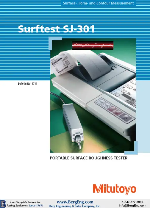
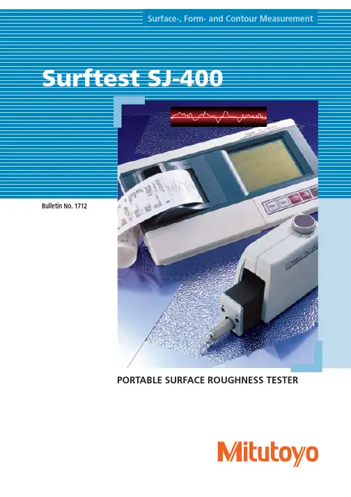
•The large LCD window makes it easy to readmeasurement resultand analysis graph at a glance. The profile-speed thermal printer prints out clear and fast.•Designed to increaseoperability – the large keypads are used for measuringoperations, while the touch panelLCD is used for setting various measurement conditions.•Measured data can be downloaded to a PC. Various analyses can be made by using Surfpak-SJ, dedicated software for surface texture analysis.A portable surface roughness testerwith a touch-panel LCD and a built-in printer.Surftest SJ-301Conforming to various standards•Conforming to the JIS (1994/1982),ISO, DIN, and ANSI standards.•Additionally, the horizontal roughness parameters S, Sm, tp (mr) can be reported. The SJ-301 also performs such special parameters as plateau rate and RK-related parameters.Storing measurement conditions and data•The SJ-301 main unit can store a maximum of 5 sets of measuring conditions. Individual measuring conditions can be selected for each workpiece.•The measuring conditions stored in the SJ-301 can be recalled and switched by direct key operations.•Measured data can be saved at the measurement site and be printed out or recalculated later.•By using an optional memory card, a maximum of 20 sets of measuring conditions, measured data, and statistical results can be stored.High-speed thermal printer•Equipped with a highly sophisticated,high-speed thermal printer.•Selectable orientation for printout –Choose the portrait for conventional printout or the landscape for printing out the image as it is displayed.•BAC (Bearing Area Curve) and ADC (Amplitude Distribution Curve) can be printed out.Key-masking function•This function limits touch panel operation to prevent the detector calibration data and measuring conditions from being altered or deleted.•Measuring conditions can be easily controlled among multiple users.Landscape printoutPortrait printoutResistance to environment•The SJ-301 keypads have excellentdurability -- No need to worry about oil stains from the user's hand.Reading profiles in the LCD window•Measurement results and analysis profiles can be read in the LCD window.•Signal waves can be scrolled smaller or larger, enabling the operator to read fine details.Customization function•The user can select only theparameters needed from a variety of surface roughness parameters provided.Mobility•A built-in buttery in the SJ-301 makes it possible to inspect surface roughness even at a site where there is no electrical outlet available.•Portable and convenient – the drive unit and the detector can be stored in the display unit. (Carrying case is a standard accessory.)•Measurement can be performed while the display unit is in the carrying case.The carrying case can be used to protect the display unit.Auto calibration•Calibration can be easily performed by simply inputting and measuring the Ra value inscribed on the roughness reference specimen.•No adjustment with a tool, such as a volume adjustment, etc. is required.Statistical analysis functions•Statistical analysis of one parameter is possible.•Displays and prints frequency histograms as well as statisticalcalculation results (average, standard deviation, maximum value, minimum value, pass ratio).GO/NG judgement function•Tolerance values in three-steps can be set for the surface roughness parameters.•Judgment symbol is displayed in the result display for a quick judgment of GO/NG.Selectable language for display/printoutDisplay/printout language is selectable from among English, German, French,Italy, Spanish and Japanese.Surftest SJ-301 Arbitrary evaluationlength•An arbitrary evaluation length withinthe range of 0.3 mm - 12.5 mm (Unit:0.1 mm) can be set.•Measurement in a limited space, wheremeasurement is difficult under themeasuring conditions in accordancewith JIS standards, is made possible byusing the start-up OFF function.One-step detectorreplacement•Special detectors are available formeasurements that cannot beperformed with a standard detector -such as measurement of small-diameters and deep-grooves.•No tool is required for replacing thedetector. Simply pull out and insert adetector.•Just one SJ-301 can performmeasurement on a variety ofworkpieces, since various types ofdetectors, depending on theworkpiece, can be used.25.2mm (.99")Approx. 21mm (.83")horizontallyApprox. 2mm (.08")verticallyHigh-accuracy detector•SJ-301 employs a differentialinductance method, which is used inhigh-end models.•Measurement with a high-accuracyand a wide measuring range of350µm.•Parameters that require high-accuracyfeed such as Sm and S can bemeasured with the SJ-301.•The detector can be retracted into thedrive unit when the SJ-301 is notperforming a measurement.room to build a highly expandable desktop evaluation system.Surftest SJ-301Specifications**Evaluation length can be specified arbitrary in the range from 0.3mm (.01”) to 12.5mm (.49”).Roughness specimenSurftest SJ-301MichiganPhone: (734) 459-2810IllinoisPhone: (630) 978-5385CaliforniaPhone: (626) 961-9661MassachusettsPhone: (978) 692-8765IndianaPhone: (317) 577-6070North CarolinaPhone: (704) 875-8332Coordinate Measuring Machines Small Tool Instruments and Data ManagementHardness Measuring Sensor Systems Optical Measuring Digital Scale and DRO Systems Surface-, Form- and Contour MeasurementVision Measuring Systems Note: All information regarding our products, and in particular the illustrations, drawings, dimensional and performance data contained in this pamphlet, as well as other technical data are to be regarded as approximate average values. We therefore reserve the right to make changes to the corresponding designs, dimensions and weights. The stated standards, similar technical regulations, descriptions and illustrations of the products were valid at the time of printing. In addition, the latest applicable version of our General Trading Conditions will apply. Only quotations submitted by ourselves may be regarded as definitive.Job No.11B-7。
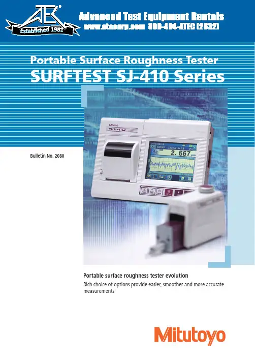
Form MeasurementBulletin No. 2080Portable surface roughness tester evolutionRich choice of options provide easier, smoother and more accurate measurements1981Color-graphic LCDThe color-graphic LCD with excellent visibility The display interface supports 16 languages.Backlight providedA backlight improves usability in dim testing Easy to use and highly functionalThis portable surface roughness tester is equipped with analysis functionality rivaling that of benchtop surface roughness testers.Complies with many industry standardsThe Surftest SJ-410 complies with the Applicable standardsEnhanced power for making measurements on siteMultilingual supportIcon display Data compensationSimple contour analysis functionText displayA wide range, high-resolution detectorMeasuring range/ resolution 800µm/0.01µm 80µm/0.001µm 8µm/0.0001µmHigh straightness drive unitStraightness/ traverse length 0.3µm/25mm (SJ-411)0.5µm/50mm (SJ-412)High accuracy measuringSJ-412SJ-411Memory card (optional) is supportedThe measurement conditions and data can be stored in a memory cardA variety of interfaces supplied as standardThe external device interfaces that come as standard include USB, RS-Access to functions can be restricted by a passwordA pre-registered password can limit use of measurement conditionsThe unit is easily transported in a dedicated carrying casewhich includes holders for the accessories as well as thetester itself. (Standard accessory.) Interfaces Data storagePassword protectionCarrying case→High-speed printer prints out measurement results on siteA high-quality, high-speed thermal printer prints out measurement results.It can also print a BAC curve or an ADC curve as well as calculatedresults and assessed profiles. These results and profiles are printed outin landscape format, just as they appear on the color-graphic LCD.PrinterA sturdy key-sheet-button panel with superior durability in any en-vironment is provided. For repeat measurement of the same work,Key-sheet buttonsS ur f test4Enhanced measuring functions•Height/tilt adjustment unit (Standard accessory)The height/tilt adjustment unit comes as standard for leveling the drive unit prior to making skidless measurements and, supported by guidance from the unique D.A.T. function, makes it easy to achieve highly accurate alignment.leveling: leveling table*1, 3-axis alignment table*1 or tilt adjustment unit*1. *1: For details about optional products, see P6-7.Powerful support for levelingPatent registered in Japan, U.S.A.. Patent pending in GermanyYour choice of skidless or skidded measurementPatent registered in Japan, U.S.A.. Patent pending in GermanyHeight adjustment knob•Skidded measurementIn skidded measurements, surface features are measured with reference to a skid following close behind the stylus. This cannot measure waviness and stepped features exactly but the range of movement within which measurement can be made is greater because the skid tracks the workpiece surface contour.•Skidless measurementSkidless measurement is where surface features are measured relative to the drive unit reference surface. This measures waviness and finely stepped features accurately, in addition to surface roughnness, but range is limited to the stylus travel available. The SJ-410 series supports a variety of surface feature measurements simply by replacing the stylus.Fulcrum point of StylusStylus Traverse directionfeatures: SkidlessUsually, a spherical or cylindrical surface (R-surface) cannot be evaluated, but, by removing the radius with a filter, R-surface data is processed as if taken from a flat surface.Step Dimensions Step volumeCoordinate differenceMore measuring functions than expected from a compact testerPreviously measured data can be recalculated for use in other evaluations by changing the current standard, assessed profile and roughness parameters.A single measurement enables simultaneous analysis under twodifferent evaluation conditions. A single measurement allows calculation of parameters and analysis of assessed profiles without the need for recalculation after saving data, contributing to higher work efficiency.Point group data collected for surface roughness evaluation is used to perform simplified contour analysis (step, step height, area and coordinate variation). It assesses minute forms that cannot be assessed by a contour measurer.This function allows a sampling length to be arbitrarily set in 0.01mm increments (SJ-411: 0.1mm to 25mm, SJ-412: 0.1mm to 50mm). It also allows the SJ-410 series to make both narrow and wide range measurements.The “OK” symbol means the measurement is within the limits set; “NG” means it is not, in which case an arrow points to either the upper or lower limit in the printout.An “OK/NG” judgment symbol is displayed when limits are set for the roughness parameter. In case of “NG,” the calculated result is highlighted. The calculated result can also be printed out.Surface roughness measurement requires a run-up distance before starting the measurement (or retrieving data). When the SJ-410 Series measures, its run-up distance is normally set to 0.5mm. This distance, however, can be shortened to 0.15mm using the narrow part measurement function (starting from the origin point of the drive unit). The function extends the possibility of measurement of narrow locations such as grooves in piston ring / O-ring mounts.This function samples stylus displacement for a specified time without engaging detector traverse, which enables use as a simplified vibration meter or displacement gage incorporated in another system.RecalculatingAssessing a single measurement result under two different evaluation conditionsSimple contour analysis functionArbitrary sampling length settingGO/NG judgement functionNarrow space measuring function Patent pending in JapanReal sampling3.52.5Example: surface roughness measuring Example: surface roughness measuringof mounting groove for O-ring Overruns surface using 0.5mm run-upthe measurementc=0.8mmThe run-up distance can be shortened to 0.15mm by measuring from the origin point.•Narrow space measuring Typical applications6Optional AccessoriesThree new optional products are available to be attached to the manual column stand (No.178-039). You can choose the unit that suits your application.Or, you can also use the three products in any combination. Using the optional units makes SJ-411/412 more convenient and easier to use to ensure accurate measurements.Can be adjusted to match the height of the item to be measured.Options for simple column standSimple column standNo.178-039Vertical adjustment range: 250mm Dimensions: 400×250×578mm Mass: 20kg* C annot be used when the tester’s main unit is an older model (SJ-401/402).•Auto-set unit (178-010)*This unit enables the vertical (Z axis) direction to be positioned automatically (auto-set function).A single button operation completes a series of operations from measurement, saving and auto-return (saving and auto-return can be switched on and off by operating the drive unit).•Tilting adjustment unit (178-030)*This unit is used for aligning the workpiece surface with the detector reference plane. It supports the DAT function to make the leveling of workpiece surfaces easier.•X-axis adjustment unit (178-020)*This unit helps fine-tune the horizontal (X axis) direction.Preliminary measurementTilt adjustmentComplete set of optional units for the manual column standAuto-set unit10m m12.5mm 12.5mm±1.5°7The tester includes X- and Y-axes micrometer heads. This makes axis alignment much easier because the tilt adjustment center is the same as the rotation center of the table.(Code No.178-042-1/178-043-1)This table helps make the alignment adjustments required when measuring cylindrical surfaces. The corrections for the pitch angle and the swivel angle are determined from a preliminary measurement and the Digimatic micrometers are adjusted accordingly. A flat-surfaced workpiece can also be leveled with this table.The levelling table can be used to align the surface to be tested with the detector reference plane. The operator is guided through the procedure byscreen prompts.XY leveling tablesPrecision viseCylinder attachmentReference step specimen3-axis Adjustment Table: 178-047Patent registered in Japan, U.S.A.. Patent pending in GermanyDAT Function for the optional leveling tablePatent registered in Japan, U.S.A.. Patent pending in GermanyDAT screen guides the user when levelingDigimatic micrometer No.178-048Inclination adjustment angle: ±1.5°Table dimensions: 130×100mmMaximum load: 15kg•Fits on the stand.This block can be positioned on top of cylindrical objects to perform measurements.No.12AAB358Diameter: ø15~60mm Configuration:•Cylindrical measurement block •Auxiliary block•ClampUsed to calibrate detector sensitivity.No.178-611Step nominal values: 2µm/10µm•T-groove dimensions•Movement is in X- and Y-axes only.Application178-042-1178-049Unit: mm*Drive unit not included.8Optional Accessories: Detectors / StyliStandard stylusDouble-length for deep hole *2*1: Tip angle 60°*2: For downward-facing measurement only.*3 :44.7DetectorsUnit: mmExtension rodsStyliUnit: mm14601011.5• 12AAG202 Extension rod 50mm• 12AAG203 Extension rod 100mm* No more than one extension rod can be connected.Styli Unit: mm For deep groove (10mm)For deep groove *2 (20mm)Please contact any Mitutoyo office for more information.10Optional Accessories: For External Output• OS: Windows XP-SP3 Windows Vista Windows 7• Spreadsheet software: Microsoft Excel 2002 Microsoft Excel 2003 Microsoft Excel 2007 Microsoft Excel 2010Required environment*This program can be downloaded free of charge from the Mitutoyo website.http://www.mitutoyo.co.jp The optional USB cable is also required.• USB cable for SJ-410 series No.12AAD510*Windows OS and Microsoft Excel are products of Microsoft Corporation.• Printer paper (5 rolls)No.270732• Durable printer paper (5 rolls)No.12AAA876• Touch-screen protector sheet (10 sheets) No.12AAN040• Memory card (2GB) *No.12AAL069• Connecting cable (for RS-232C) No.12AAA882* m icro SD card (with a conversion adapter to SD card)Contour / Roughness analysis software FORMTRACEPAKSimplified communication program for SURFTEST SJ seriesOptional accessories, consumables, and others for SJ-410More advanced analysis can be performed by loading SJ-410 series measurement data to software program FORMTRACEPAK via a memory card (option) for processing back at base.The Surftest SJ-410 series has a USB interface, enabling data to be transferred to a spreadsheet or other software.We also provide a program that lets you create inspection record tables using a Microsoft Excel* macro.By connecting this printer to the Surftest SJ-410's digimatic output,you can print calculation results, perform a variety of statistical analyses, draw a histogram or D chart, and also perform complicated operations for X-R control charts.This unit allows you to load Surftest SJ-410 calculation results (SPC output) into commercial spreadsheet software on a PC via a USB connector. You can essentially use a one-touch operation to enter the calculation results (values) into the cells in the spreadsheet software.USB keyboard signal conversion type*IT-012UNo.264-012-10* R equires the optional Surftest SJ-410 connection cable.1m: No.936937 2m: No.965014USB-ITN-DNo.06ADV380DDigimatic mini processor DP-1VRCalculation results input unit INPUT TOOLNo.264-504 -5ASJ-410→DP-1VR Connecting cable 1m: No.936937 2m: No.965014This unit allows you to remotely load Surftest SJ-410 calculation results (SPC output) into commercial spreadsheet software on a PC.You can essentially use a one-touch operation to enter the calculation results (values) into the cells in the spreadsheet software.Measurement Data Wireless Communication System U-WAVEU-WAVE-T *(Connects to the SJ-410)No.02AZD880D* R equires the optional Surftest SJ-410 connection cable.No.02AZD790DU-WAVE-R(Connects to the PC)No.02AZD810DSpecifications*2: Only for JIS'97 standard.*3: Only for JIS'01 standard.*4: Only for ANSI standard.*5: λs may not be switchable depending on standard selected.*6: Standard deviation only can be selected in ANSI.16% rule cannot be selected in VDA.*7: Either No.178-396-2 or No.178-397-2 is supplied as a standard accessory depending on the Order No. of the main unit for SJ-410 Series.*8: The standard stylus (No.12AAC731 or No.12AAB403), which is compatible with the detector supplied, is a standard accessory.11。
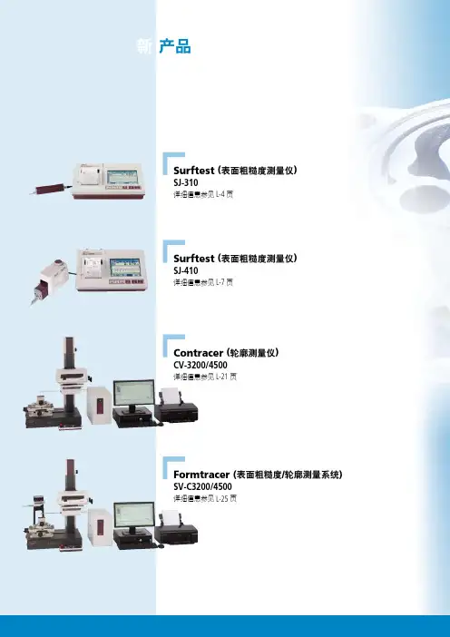
Surftest (表面粗糙度测量仪)SJ-310详细信息参见 L-4 页Surftest (表面粗糙度测量仪)SJ-410详细信息参见 L-7 页产品Contracer (轮廓测量仪)CV-3200/4500详细信息参见 L-21 页Formtracer (表面粗糙度/轮廓测量系统) SV-C3200/4500详细信息参见 L-25 页形状测量系统LLL目录Surftest (表面粗糙度测量仪)SJ-210 L-3SJ-310L-4用于 SJ-210/310选件L-5SJ-410L-7SJ-500, SV-2100L-8SJ-500P , SV-2100M4 L-9SV-3100L-10Surftest Extreme 超级表面粗糙度测量仪(CNC 表面粗糙度测量仪)SV-3000CNC/SV-M3000CNCL-11选件L-12精密量仪·量具的小知识L-17Contracer (轮廓测量仪)CV-2100L-19CV-3200 / CV-4500L-21Contracer Extreme(CNC 轮廓测量仪)选件L-23Formtracer(表面粗糙度和轮廓测量系统)SV-C3200 / SV-C4500L-25CS-3200S4L-26Formtracer Extreme(CNC 表面粗糙度和轮廓测量系统)SV-C4500CNCL-27CS-5000CNC/CS-H5000CNC L-28精密量仪·量具的小知识L-29Roundtest(圆度、圆柱形状测量仪)RA-10L-31RA-120/120P L-32RA-1600L-33RA-2200L-34RA-H5200L-35Roundtest Extreme(CNC 圆度、圆柱形状测量仪)RA-2200CNC L-36RA-H5200CNCL-37选件L-38精密量仪·量具的小知识L-41Surftest FormtracerContracerRoundtestL便携式表面粗糙度测量仪测量开始粗糙度参数选择L 轮廓显示: 一个参数的测量结果和测量轮廓Surftest SJ-310No.12AAA217**No.12AAA216No.12AAA222No.12AAA218 *退避型标准配件*配件不适于横向移动驱动器。
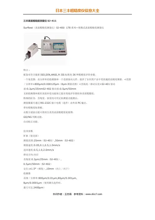
三丰表面粗糙度测量仪SJ-411Surftest(表面粗糙度测量仪)SJ-400 178系列—便携式表面粗糙度测量仪配备有符合最新ISO,DIN,ANSI,和JIS标准的36种粗糙度评价参数。
一个宽范围、高分辨率的检测器和一个直接驱动元件,提供了在同类产品中更优越的高精度测量。
<范围/分辨率>800μm/0.000125μm(8μm测量范围)<直线度/移动长度>SJ-401驱动部:0.3μm/25mmSJ-402驱动部:0.5μm/50mm无轨检测器和弧形表面补偿功能使它能有效地评价圆柱体表面粗糙度。
特细的阶差,直线度、波度均可用无轨测量功能测出。
测量数据可通过RS-232C接口电缆(选件)由外部PC输出。
带有粗糙度标准板。
由数字滤波功能可得到全真的表面粗糙度轮廓图。
GO/NG判断功能。
自动校正功能。
技术参数X轴(驱动部)测量范围:25mm(SJ-401),50mm(SJ-402)测量速度:0.05,0.1,0.5,1.0mm/s返回速度:0.5,1.0,2.0mm/s移动方向:向后直线度:0.3μm/25mm(SJ-401),0.5μm/50mm(SJ-402)定位:±1.5°(倾角),10mm(向上/向下)检测器范围/分辨率:800μm/0.01μm,80μm/0.001μm,8μm/0.0001μm(使用测头选件时,最大可达2400μm)本问作者:王忠海参考资料:检测方法:无轨/有轨测量测力:4mN或0.75mN(低测力型)测针针尖:金刚石、90º/5μmR(60º/2μmR:低测力型)导头曲率半径:40mm检测方法:差动电感式电源:通过AC适配器/可充电镍氢电池电池寿命:最多可测量600次(不带打印)充电时间:15个小时数据输出通过RS-232C端口/SPC输出尺寸(WxDxH)控制器:307x165x94mm高度-倾角调整装置:131x63x99mm驱动部:128x36x47mm(SJ-401),155x36x47mm(SJ-402)重量控制器:大约1.2kg高度-倾角调整装置:大约0.4kg驱动部:0.6kg(SJ-401),0.7kg(SJ-402)评估能力评估轮廓:P(主轮廓),R(表面粗糙度轮廓),W(滤波波度轮廓),DIN4776、粗糙度motif、波形motif评估参数:Ra,Ry,Rz,Rq,Pc,R3z,mr,Rt,Rp,Rv,Sm,S,?c,Rk,Rpk,Rvk,Mr1,Mr2,A1,A2,Lo,Ppi,R,AR,Rx,Da,Dq,Ku,HSC,mrd,Sk,W,AW,Wte,Wx,Vo分析图表:支撑曲线(BAC1/2)、振幅分布曲线(ADC)滤波类型2CR,PC75,高斯截止波长0.08,0.25,0.8,2.5,8mm取样数:X1,X3,X5,XL任意长度(XL):0.1-25mm(0.1-50mm:SJ-402),0.1mm增量取样长度(L):0.08,0.25,0.8,2.5,8mm打印机热敏打印机本问作者:王忠海参考资料:打印宽度48mm(纸宽:58mm)纪录倍率垂直:20X-100,000X、自动水平:1X-1,000X、自动功能客户化:显示/评价参数的选择数据补偿:R表面、倾斜补偿标尺功能:显示任意两点间的坐标差数字调整工作台功能:无轨测量时、协助调水平移动检测模式驱动部停止时输入测头移动统计过程:最大值、最小值、均值、标准差、合格率、直方图公差判断:可确定三个参数的上、下极值。
三丰粗糙度仪SJ-411特点:1、配备有符合最新ISO,DIN,ANSI,和JIS标准的36种粗糙度评价参数。
2、一个宽范围、高分辨率的检测器和一个直接驱动元件,提供了在同类产品中更优越的高精度测量。
<范围/分辨率>800μm/0.000125μm(8μm测量范围)<直线度/移动长度>SJ-401驱动部:0.3μm/25mmSJ-402驱动部:0.5μm/50mm3、无轨检测器和弧形表面补偿功能使它能有效地评价圆柱体表面粗糙度。
特细的阶差,直线度、波度均可用无轨测量功能测出。
4、测量数据可通过RS-232C接口电缆(选件)由外部PC输出。
5、带有粗糙度标准板。
6、由数字滤波功能可得到全真的表面粗糙度轮廓图。
7、GO/NG判断功能。
8、自动校正功能。
技术参数(三丰粗糙度仪SJ-411技术参数):一、X轴(驱动部)1、测量范围:25mm(SJ-401),50mm(SJ-402)2、测量速度:0.05,0.1,0.5,1.0mm/s3、返回速度:0.5,1.0,2.0mm/s4、移动方向:向后5、直线度:0.3μm/25mm(SJ-401), 0.5μm/50mm(SJ-402)6、定位:±1.5°(倾角),10mm(向上/向下)二、检测器1、范围/分辨率:800μm/0.01μm,80μm/0.001μm, 8μm/0.0001μm(使用测头选件时,最大可达2400μm)2、检测方法:无轨/有轨测量3、测力:4mN或0.75mN(低测力型)4、测针针尖:金刚石、90o/5μmR (60o/2μmR:低测力型)5、导头曲率半径:40mm6、检测方法:差动电感式7、电源:通过AC适配器/可充电镍氢电池8、电池寿命:最多可测量600次(不带打印)9、充电时间:15个小时10、数据输出通过RS-232C端口/SPC输出11、尺寸(WxDxH)12、控制器:307x165x94mm13、高度-倾角调整装置:131x63x99mm14、驱动部:128x36x47mm(SJ-401), 155x36x47mm(SJ-402)三、重量1、控制器:大约1.2kg2、高度-倾角调整装置:大约0.4kg3、驱动部:0.6kg(SJ-401),0.7kg(SJ-402)三丰粗糙度仪SJ-411评估能力评估轮廓:P(主轮廓),R(表面粗糙度轮廓),W(滤波波度轮廓), DIN4776、粗糙度motif、波形motif评估参数:Ra,Ry,Rz,Rq,Pc,R3z,mr,Rt,Rp,Rv,Sm,S,?c,Rk,Rpk,Rvk,Mr1, Mr2,A1,A2,Lo,Ppi,R,AR,Rx,Da,Dq,Ku,HSC,mrd,Sk,W,AW, Wte,Wx,Vo三丰粗糙度仪SJ-411功能1、客户化:显示/评价参数的选择2、数据补偿:R表面、倾斜补偿3、标尺功能:显示任意两点间的坐标差4、数字调整工作台功能:无轨测量时、协助调水平5、移动检测模式:驱动部停止时输入测头移动6、统计过程:最大值、最小值、均值、标准差、合格率、直方图7、公差判断:可确定三个参数的上、下极值。
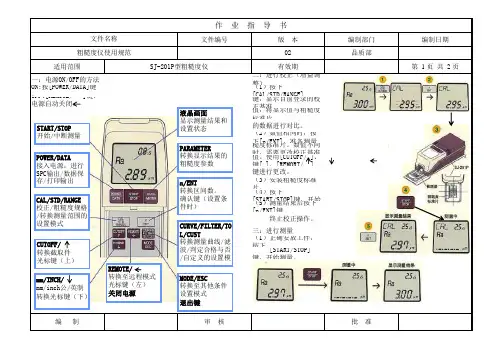
产品型号:SJ-201P所在地:北京海淀区产品描述:Mitutoyo三丰粗糙度仪SJ-201P|日本三丰表面粗糙度仪Mitutoyo SJ-201P三丰表面粗糙度测量仪 SJ-201PSurftest SJ-201P/SJ-201M便携式表面粗糙度测量仪用于生产现场的智能化工具大型LCD液晶显示器,使您的观测更加方便。
便携式设计,可以根据您的需要在任何地方进行测量。
驱动/检测装置可以与显示装置分离,用以轻松测量粗糙的定向工件。
测量范围宽达350μm(-200μm至+150μm)。
配备有符合ISO,DIN,ANSI,JIS标准的多种粗糙度评估参数。
提供19种分析参数,其中包括Ra,Rq,Rz,和Ry等基本参数。
定制功能的使用可以将不必要的参数省去不予显示。
可对目标参数使用GO/NG判断功能。
自动校准功能,可以复合地进行增益调节。
自动睡眠功能,可以有效的节省能源。
即使在切电源以后,仍然可以保留10组测量数据。
可以输出SPC格式数据。
通过RS-232C连接线(选件),可以将数据传送到PC或者其他设备上提供了两种电源系统(AC适配器/内置可充电电池)。
带有专用的便携式仪器箱,方便您安全运输。
为您提供了一个精密的粗糙度标准。
使用打印机选件(178-420),可将测量数据打印出来。
设定修改键:推开显示装置的顶盖以后,就可以看到下面的设定修改键。
使用REMOTE键,可以进行数据输出:RS-232C连接线连接打印机,就可以将测量的轮廓打印出来。
选用相应的连接线,还可以实现与PC的连接。
SPC格式数据输出与通信:SJ-201型机器可以通过RS-232C连接线连接外部设备,实现SPC格式数据输出与通信。
探测器保护功能:如果需要移动SJ-201型仪器或者长时间不使用时,使用擦测器保护功能将探测器收入主体内就能够防止意外撞击所带来的损坏。
测量:在测量模式中,按下[START/STOP]键启动探测器在LCD液晶显示器上出现“----”提示符,在测量完成时变为显示参数值。
带超薄按键和轻触面板的SJ-301SJ-301 超薄按键显示和轻触面板。
本章介绍基本的功能,是轻触面板上的超薄按键、轻触面板、屏幕的展列。
2.1 超薄按键功能测量开始/停止,打印,测量情况通知,数据输出,和另一些SJ-301超薄按键的操作功能。
在这里介绍每个超薄按键的功能。
显示超薄按键2-1每个按键功能[PRINT]key开始和停止打印。
按压该键开始打印,再次按压将停止打印。
提示:打印相关信息,请参阅4.5“ PrintingMeasuredResults ”。
[FEED] key送打印纸[CONDITION READ] key调用测量条件存储器当中的记忆内容会显示到显示器上。
该功能因此被强制切换。
•测量情况通知按压该键显示选择文件窗口在轻触面板上。
在窗口中轻触头条选择文件之后选择所需的文件名。
头条提示:测量情况文件也能通知测量设置与显示屏上。
关于测量情况文件请参阅8.2“保存/取消测量情况”。
•强制转换强制转换是当按压[POWER]键的时候一会儿为[COONDITIONREAD]键。
重要信息强制转换只能在内置电池使用时。
如果SJ-301不使用时间超过一年半以上的话,内置电池可能会放电。
为了避免强制转换,电池不能放在设备里。
其他的原因也可能导致电池额外放电。
提示强制转换的详细资料,请参阅11.3电池充电强制转换2-22. 超薄按键和轻触面板设计的SJ-301[DATA]key输出SPC数据到一个数据处理器等等,和存储在一个记忆卡。
它也能使用语言转换。
•SPC 数据输出SJ-301预先连接到数据处理器。
因此,设置功能[DATA]键为SPC数据输出。
如果按压[DATA]键后,SPC数据输出被运行参数输出到显示器上,屏幕上缺少部分数据。
输出的参数被显示在荧屏上面。
(按压[DATA]键输出SPC 数据Ra值。
)提示关于SPC数据输出请参阅9.1“SPC输出”。
标准的轮廓数据存储记忆卡预先在 SJ-301 中插入一张记忆卡片。
中文名称:轮廓仪英文名称:profilometer定义:能描绘工件表面波度与粗糙度,并给出其数值的仪器。
应用学科:机械工程(一级学科);量具与量仪(二级学科);量仪(二级学科)概述:轮廓测试仪是对物体的轮廓、二维尺寸、二维位移进行测试与检验的仪器,作为精密测量仪器在汽车制造和铁路行业的应用十分广泛。
三丰轮廓仪CV-3100/CV4100(轮廓测量仪)详细介绍:Mitutoyo三丰轮廓仪 CV-3100/CV4100,Contracer(轮廓测量仪)CV-3100/CV-4100218系列—轮廓测量仪特点:•大幅度提高了驱动速度(X轴:80mm/s,Z2轴:20mm/s),近一步降低了总测量时间。
•为了在一定时段内维持仪器的直线度规格,三丰公司采用了具有极佳的耐摩擦性及稳定性的高硬度陶瓷导轨。
•大量的外周设备选件支持CNC模式,从而可以很容易实现CNC测量。
•驱动装置(X轴)和立柱(Z2轴)中集成了高精度线性编码器(Z2轴为ABS型),从而提高了在垂直方向持续自动测量小孔和不易定位工件的重复精度。
•X轴精度:±(0.8+0.01L)μm,Z1轴精度:±(0.8+|0.5H|/25)μm*,针对高精度工件的测量所设计。
*CV-4100S4,H4,W4型L为驱动长度,H为测量高度(mm)•CV-4100系列的驱动装置集成了激光全息测微计检测器,在Z轴(垂直方向)的窄/宽测量范围内,提供卓越的精度和分辨率。
自动测量功能•配备有大量支持CNC模式的外周设备选件,从而可实现自动测量功能。
技术参数:X轴测量范围:100mm或200mm分辨率:0.05μm检测方法:反射型线性编码器驱动速度:80mm/s和手动测量速度:0.02-5mm/s移动方向:向前/向后直线度:0.8μm/100mm,2μm/200mm*当X轴在水平方向上指示精度:±(1+0.01L)μm(CV-3100S4,H4,W4)(20°C时)±(0.8+0.01L)μm(CV-4100S4,H4,W4)±(1+0.02L)μm(CV-3100S8,H8,W8)±(0.8+0.02L)μm(CV-4100S8,H8,W8)*L为驱动长度(mm)倾斜范围:±45°Z2轴(立柱)垂直行程:300mm或500mm分辨率:1μm检测方法:ABSOLUTE线性编码器驱动速度:0-20mm/s和手动Z1轴(检测器)测量范围:±25mm分辨率:0.2μm(CV-3100),0.05μm(CV-4100)检测方法:线性编码器(CV-3100),激光全息测微计(CV-4100)指示精度:±(2+I4HI/100)μm(CV-3100)(20°C时)±(0.8+I2HI/100)μm(CV-4100)*H为水平位置上的测量高度(mm)测针上/下运作:弧形运动测针方向:向上/向下测力:30mN跟踪角度:向上:77°、向下:87°(根据表面粗糙度,使用标准单切面测针)测针针尖半径:25μm、硬质合金针尖基座尺寸(WxH):750x600mm或1000x450mm基座材料:花岗岩重量主机:140kg(S4),150kg(H4),155kg(W4),145kg(S8),155kg (H8),160kg(W8)控制装置:14kg遥控箱:0.9kg电源:100–240VAC±10%,50/60Hz能耗:400W(仅限主机)批量校准功能•使用专用校准规,可同时进行设备的Z轴增益,对称及针尖半径的校准。
型三丰轮廓粗糙度仪安全操作及保养规程1. 引言型三丰轮廓粗糙度仪是一种用于测量工件表面粗糙度的专用仪器。
为了确保仪器的正常运行,保护使用人员的安全,并延长仪器的使用寿命,需要遵守一定的操作规程和保养要求。
本文档将介绍型三丰轮廓粗糙度仪的安全操作和保养规程。
2. 安全操作规程2.1. 仪器使用环境要求•确保工作环境干燥、通风良好,并远离任何可能引起机械冲击和震动的设备。
•要求工作台面平整稳固,使仪器能够保持稳定的工作状态。
2.2. 仪器操作前的准备•检查仪器及电源线是否完好,如发现任何损坏应立即停止使用,并联系维修人员进行维修。
•预热仪器至正常工作温度,一般情况下需要预热10分钟左右。
2.3. 仪器的正确使用•在使用之前,仔细阅读使用手册,并确保自己完全理解所有的操作方法和注意事项。
•需要按照测量要求选择合适的测量探头,并正确安装到仪器上。
•在开始测量之前,先对测量探头进行校准,保证测量的准确性。
•在测量过程中,保持手持仪器平稳,并避免与测量工件发生碰撞。
•仪器测量完成后,及时关闭电源,并尽量避免频繁开关。
2.4. 危险事故的应急处理•发生仪器故障或任何意外情况时,应立即停止使用,并关闭电源。
•如果可能,请在仪器操作过程中戴上防护手套和护目镜等必要的防护设备。
•在紧急情况下,及时与维修人员联系,并按照其指示进行处理。
3. 仪器保养规程3.1. 日常保养•每次使用后,应及时清洁仪器表面的灰尘和污垢。
•使用干净的软布擦拭仪器,并避免使用任何腐蚀性的清洁剂。
•定期检查仪器的电源线和连接线是否损坏,如有损坏应尽快更换。
3.2. 仪器存放•当仪器不使用时,应将其放置在干燥、清洁、温度适宜的存放环境中。
•避免阳光直射和高温环境,以免损坏仪器的电子元件和塑料部件。
•仪器长期不用时,建议定期开启并进行简单的功能测试,以确保其性能不受影响。
3.3. 定期维护•按照使用手册中的要求,定期保养仪器并进行维护。
•定期检查仪器的接线和连接是否松动,如有松动应及时紧固。
SJ-401粗糙度测试仪操作说明测量操作规程(仅供参考)总的测量流程:■根据要求修改测量条件下表列出SJ-400可修改的测量条件,出厂前SJ-400已经被设定成表中的默认值。
调整校准和测量如果在建立样本或工件的校准或测量前SJ-400已经安装了,必须实行“向上/向下测量(调整驱动/探测单元的高度)以及”水平测量(调整驱动/探测单元的斜度)。
4.2.1 向上/向下测量实行向上/向下测量时,使用高度/倾斜调整单位和简单的立柱(可选).■用高度/倾斜调整单位进行向上/向下测量通过旋转在高度4.2.24.2.3Tip提示:使用水平工作台时,简易的柱体是必须的。
关于如何使用柱体的资料,请参考节“简易柱体”。
■带DAT功能的倾斜调整在触摸屏的主页上使用DAT功能实行DAT测量,以及根据测量结果调节高度-倾斜调整装置或水平工作台,方法如下:1.在主页上触摸“DAT”按钮,显示DAT测量屏幕。
2.如果高度-倾斜调整装置是用水平测量,打开屏幕通过触摸“倾斜调整数量装置“按钮显示倾斜旋钮的转动数量。
如果使用水平工作台测量,进入程序3。
3.如果使用水平工作台,通过按“ZERO/ABS“按钮进行零位设定计量显示器数值,如果使用高度-倾斜调整单元,进入程序4。
4.在显示装置上按“START/STOP”键。
实行DAT测量。
水平测量调整数量在屏幕上显示出来。
5.为了防止探测器或触针的损坏,在调整倾斜前,将触针从工件上移开。
高度-倾斜装置:通过顺时针转动倾斜按钮来升高驱动/探器装置。
水平工作台:通过顺时针转动立柱手柄升高驱动/探器装置。
6.根据屏幕上各个的高度-倾斜装置转动的数量或水平工作台调整数量,通过转动倾斜按钮或测微头来调整水平。
Important:数显头转动方向取决于驱动/探测装置和数显头的位置关系,如上表中的图形已经写明了转正方向。
转动方向相反,位置关系也是相反的。
7.调整完成后,在工件上设置探针合适的位置,然后通过上-下移动把探针放到靠近工件中心的位置。