DMAGE中文操作说明书
- 格式:doc
- 大小:10.51 MB
- 文档页数:58

EagleXtreme中文操作手1.18 加熱器控制可編程溫度控制器用於分別地設定加熱後平台與工作平台的溫度。
這兩種控制都具有數位輸出、自動微調性能,也具有熱量損失與配線電阻補償提供負值補償功能。
當溫度超出上、下限時,螢幕將會顯示一訊息而且銲接動作也將自動中止。
訊息框與加熱器顯示列信息按鈕T otal Wi r es Number預熱溫度設定P airs of Number ofAlignment Units perP oint Clamp銲接後溫度設定程式名稱Number of Number ofRow per ColumnClamp per Clamp熱風控制銲接溫度設定Z 熱量控制1.19 可編程電子放電產生器本手冊中所提到的電子放電產生器是在熱金線銲接工序中把細微的金線形成銲球的裝置。
下圖顯示前面板的7個指示燈,它為操作者提供電子放電產生器與觸動結果的狀態。
備註: 若有某些錯誤情況的附加訊息,指示燈可能同時亮。
On Power OnTriggerOff ShortSG- 55 OpenTime OutW/S ConnectionGap Wide可編程電子放電產生器指示燈面板可編程電子放電電源開啟發生器打開時燈會點亮。
(注意:當維修此裝置時,控制板必須插入使 LED 開著)Trigger(觸動器)當觸動打火時此燈立刻亮燈,它與電流控制電晶體同時被打開並在打火持續時間内保持亮燈。
Short(短路)由於不規則的線尾形成,金線與打火棒之間的間隙可能會因短路而不能形成銲球。
小於 1100 V之非常低的擊穿電壓也將被視爲短路條件,因爲它不屬於正常範圍。
Open(開路)如果無線存在或由於其它原因而無擊穿電壓發生,將會出現一個OPEN(開路)錯誤報告。
如果輸出關閉開關處於 OFF位置,也會出現此種狀況。
Time Out(超時)最大打火時間被限定為15 ms,如果到時銲球尚未完全形成將會出現此錯誤。
如果選擇的電流太低及銲球尺寸設定太高也會出現此錯誤,在這種情況下形成銲球需大於15 ms。
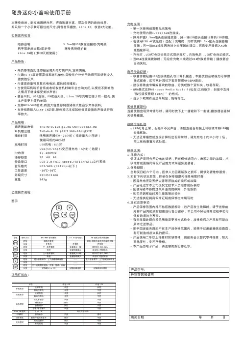
随身迷你小音响使用手册本随身音响,能发出清晰自然声音饱满丰富层次分明的音响效果,却只有一个小手掌可握住的尺寸,具备音乐播放、、收音3大功能。
、、Line INMini sound box user manualMini sound box is personal stereo with clear, nature sound.It could be hold by a small palm and have music play, Line in, FM function.Accessaries :3.5mm convert to USB line+Charge line Bag Line in line Handle Holder fixture + Fixed Belt Features :·High-textured aluminum metal surface facilitate outdoor, indoor use;·Built-in Hi-Fi high-quality and high-efficiency speaker monomer, youcan still hear heavenly music even outdoors.·Built-in high-capacity rechargeable battery, support long play.·You can continue to enjoy the heavenly music when using headphones to listen to music or listen to the radio ,it will automatically turn off the loudspeaker, not accessible to anyone else.·Headset, USB connector, FM radio antenna, Line IN and charging are use the same jack wich make the product more beautiful and simple·Support MP3/WMA format, building in large capacity memory to store number of music files.·Support Line IN function, receiving notebook or other audio source to amplify the power. Product Specification :Loudspeaker output: THD+N=0.15% @ 1.5W SNR=94db @ 1.5W Earphone output: THD+N=0.6% @ 32Ω SNR = 92 db @ 32Ω Play time: 9~20 hours with loudspeaker (depend on the volume) ;70 hours with earphoneCharge time: USB charge :7 hours USB(5V/1A)AC transformer charge :4 hours (Optional) FM: 87~108MHz Storage: 2G 、4G 、8GInterface transfer: USB 2.0 Full speed, FAT16/FAT32 file system Audio format : MP3 / WMAWork temperature: -10°C ~ 50°C Dimension : 88 x 35 x 35 mm Weight : 143 g Instructions :Indicator light :Charge I ndicatio n:• The batt ery shou ld be cha rged fully befo re using at first ti me • 3.5mm /USB line with cha rge• Opened cover, C onnect 3.5mm plug to the player and the other end of USB plug to compute r USB interface• If you us e USB A C adapte r (option al) charg ing, Con nect 3.5mm plug to player , connect the other end of USB plug to socket of the transform er , and then insert the AC power transform er When chargin g, LED li ght will long time bri ght, whe n the pow er is full, LED wil l crush o ut.• When th e USB ca ble is ex tracted, the playe r will pow er off au tomatica lly.Music tra nsmissio n:• Down lo ad the m usic file with MP3/WMA fo rmat, an d transfe r to the p lay via U SB line.• Classifie d the mu sic into s everal fo lders .• WMA format support Window s Media Audio 9 including the edition before but not support “DRM ” format .System reset:When th e player could'n w ork norm ally, plea se press forward and nex t button together , the play er will po wer off a nd reset .Troubles hooting :• When LE D bright, but can't hear vo ice, plea se check whether theearp hone have been connect ed normally or USB line have been removed . • If the pla yer does n 't work no rmally or it shows error when connect with the compute r , please charge about half pass one hour and then reset the system .Warrant y Descri ption :1.Warra nty type:Make sure the products meet publishe d specifica tions . We will repair orreplace the product when the function have trouble during the warranty period .2. Warrant y period :Supply the mainten ance service for free within six months from the date of purchas e withou t human element destroy .3. You nee d to pay for the m aintenan ce charge for the followingconditio n : • The abn ormal vo ltage an d natura l disaste rs cause the dam age.• The prod uct have been ma intained or dismo unted by the pers on who h ave not b e author ized by o ur techn ical staff .• User cau se the da mage or the failure of the appeara nce . • Fall dam age• Can not provide the deal er's warr anty or t he warra nty is no t filled .4. Other notesWarrant y is not i nclude th e data. W hen the p roduct w ork abys sal, plea se copy you r data fir st. We a re not su re to kee p the inte grity of the dataWe need to repla ce the sp are parts sometim es when ma intenanc e, so it is possible that som e parts a re not or iginal.Handle h older fix ture in n ot includ e in the w arranty.We will r eplace th e part if i t is avail able or e lse witho ut maint enance a fter the prod uct have been us ed more than 2 y ears.It is e lectronic product , please keep aw ay from t he water .。
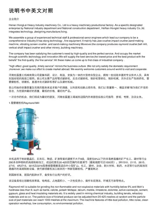
说明书中英⽂对照企业简介Henan HongLei Heavy Industry machinery Co., Ltd is a heavy machinery productional factory .As a specific designated enterprise by National industry department and National construction department , HeNan Honglei heavy industry Co.,ltd. integrates technology ,designing,manufacture,fixing.We assemble a group of experienced technical staff & professional senor engineer,which lead our company to be a comprehensive industry.It has stong technology , fine equipment. It mainly has Jaw crusher,impact crusher,sand-making machine, vibrating screen crusher ,and sand-making machinery.Moreover,the company produces raymond crusher,ball mill, vertical shaft impact crusher and other minery ,building machinary.The company has been satisfying the customer's need by high-quality and the perfect service. And occupy the market through scientific technology and innovation.We will supply the best service,the lowest price and the best product with the beliefs" the first quality ,the fine service".All these make us come up to first class of industrial company ."high effect ,good quality ,timely service" mirrors the business culture .We not only satisfy the domestic requirement;moreover ,we make our effort to create market abroad. We warmly welcome customers around world to visit and cooperate.河南宏磊重⼯机械有限公司是集科研,设计,制造,安装为⼀体的⼤型综合型企业,拥有⼀批经验丰富的专业技术⼈员,具有实践经验的⾼级⼯程师。

贮藏条件残留。
为使CCK - 8试剂和培养基充分混匀,建议在加 入CCK - 8试剂后轻轻振摇培养板。
为了避免加样时由 于CCK - 8试剂在枪头上的残留所带来的误差,可以在 加样前用培养基稀释CCK - 8试剂并混匀后加样。
- 8甲臜,如果实验中有还原剂,请检查背景的O.D值, 即在不含细胞的培养基中加入药物,然后加入CCK - 8试剂在一定时间内检测,和不加药物的培养基进行比 较 (只加CCK - 8试剂),如果O.D值明显偏高,则说明 有反应。
变化,建议更换新鲜的培养基后再加CCK - 8试剂。
含 有酚红的培养基不影响本试剂盒做细胞活性的测定。
600 nm以上) 作为参比波长,扣除参比波长的O.D值即可。
的实验,例如中性红法或结晶紫法 ,也可在CCK - 8法 检测完后继续进行。
线 ( 具体方法参见P.3页的“制作标准曲线”)。
量和加入CCK - 8试剂后的培养时间。
来,导致每孔中的细胞数量不等,可以每接种几个孔 就混匀一下。
培养板周围一圈孔培养基容易挥发,为 了减少误差,建议培养板的四边每孔只加培养基,而 不作为指标检测孔。
少而异。
一般情况下,白细胞较难显色,因此需要较长 的CCK - 8反应时间或增加细胞数量 (~105个细胞/孔)。
悬浮细胞与贴壁细胞相比较难显色。
对于悬浮细胞, 在加入CCK - 8培养1- 4小时后,可先从培养箱中取出, 目测染色程度或用酶标仪测定决定。
若显色困难,可 将培养板放回培养箱,继续培养数小时后再确定。
对 于贴壁细胞,CCK - 8的培养时间一般为1- 4小时,但 在培养30分钟左右即可取出肉眼观察显色程度 (根据 细胞种类而定,需要摸索一下条件)。
注意:CCK - 8 的最佳反应时间以具体显色的最佳时间为准。
行孔间的差异。
加 CCK - 8试剂时,建议斜贴着培养 板壁加,不要插到培养基液面下加,容易产生气泡, 会干扰O.D值读数。
1 234567810注意事项:- 100 孔: 1 ml x 1 管试剂内含所需设备和材料:概述参考资料操作说明参考资料Q&A:。

PNOZ m EF 8DI4DO}Configurable control systems PNOZmulti 2This document is a translation of the original document.All rights to this documentation are reserved by Pilz GmbH & Co. KG. Copies may be made for internal purposes. Suggestions and comments for improving this documentation will be gratefully received.Pilz®, PIT®, PMI®, PNOZ®, Primo®, PSEN®, PSS®, PVIS®, SafetyBUS p®,SafetyEYE®, SafetyNET p®, the spirit of safety® are registered and protected trademarks of Pilz GmbH & Co. KG in some countries.SD means Secure Digital1.2Using the documentation4 1.3Definition of symbols42.2Unit features6 2.3Front view73.2System requirements8 3.3Safety regulations8 3.3.1Use of qualified personnel8 3.3.2Warranty and liability9 3.3.3Disposal9 3.3.4For your safety94.2Functions10 4.3System reaction time10 4.4Block diagram105.2Dimensions in mm11 5.3Connecting the base unit and expansion modules116.2Connection13 6.3Download modified project to the PNOZmulti system1410.2Accessories221Introduction1.1Validity of documentationThis documentation is valid for the product PNOZ m EF 8DI4DO. It is valid until new docu-mentation is published.This operating manual explains the function and operation, describes the installation andprovides guidelines on how to connect the product.1.2Using the documentationThis document is intended for instruction. Only install and commission the product if youhave read and understood this document. The document should be retained for future ref-erence.1.3Definition of symbolsInformation that is particularly important is identified as follows:NOTICEThis describes a situation in which the product or devices could be dam-aged and also provides information on preventive measures that can betaken. It also highlights areas within the text that are of particular import-ance.INFORMATIONThis gives advice on applications and provides information on special fea-tures.2Overview2.1Scope of supply}Expansion module PNOZ m EF 8DI4DO}Jumper2.2Unit featuresUsing the product PNOZ m EF 8DI4DO:Expansion module for connection to a base unit from the configurable control systemPNOZmulti 2 .The product has the following features:}Can be configured in the PNOZmulti Configurator}Semiconductor outputs:4 safety outputsDepending on the application, up to PL e of EN ISO 13849-1 and up to SIL CL 3 of ENIEC 62061}8 inputs for connecting, for example:–E-STOP pushbutton–Two-hand button–Safety gate limit switch–Start button–Light beam devices–Scanner–Enabling switch–PSEN–Operating mode selector switch}LED for:–Error messages–Diagnostics–Supply voltage–Output circuits–Input circuits}Test pulse outputs used to monitor shorts across the inputs}Monitoring of shorts between the safety outputs}Plug-in connection terminals:Either spring-loaded terminal or screw terminal available as an accessory (see orderreference)}Please refer to the document "PNOZmulti System Expansion" for the PNOZmulti base units that can be connected.2.3Front viewKey:}0 V, 24 V: Supply connections}Inputs I0 – I7}Outputs O0 – O3}LEDs:–POWER–Run–Diag–Fault–I Fault–O Fault3Safety3.1Intended useThe expansion module may only be connected to a base unit from the configurable systemPNOZmulti 2 (please refer to the document "PNOZmulti System Expansion" for details ofthe base units that can be connected).The configurable system PNOZmulti 2 is used for the safety-related interruption of safetycircuits and is designed for use in:}Emergency stop equipment}Safety circuits in accordance with VDE 0113 Part 1 and EN 60204-1The following is deemed improper use in particular:}Any component, technical or electrical modification to the product}Use of the product outside the areas described in this manual}Use of the product outside the technical details (see Technical details [ 17]).NOTICEEMC-compliant electrical installationThe product is designed for use in an industrial environment. The productmay cause interference if installed in other environments. If installed in otherenvironments, measures should be taken to comply with the applicablestandards and directives for the respective installation site with regard to in-terference.3.2System requirementsPlease refer to the "Product Modifications PNOZmulti" document in the "Version overview"section for details of which versions of the base unit and PNOZmulti Configurator can beused for this product.3.3Safety regulations3.3.1Use of qualified personnelThe products may only be assembled, installed, programmed, commissioned, operated,maintained and decommissioned by competent persons.A competent person is someone who, because of their training, experience and current pro-fessional activity, has the specialist knowledge required to test, assess and operate thework equipment, devices, systems, plant and machinery in accordance with the generalstandards and guidelines for safety technology.It is the company’s responsibility only to employ personnel who:}Are familiar with the basic regulations concerning health and safety / accident preven-tion}Have read and understood the information provided in this description under "Safety"}And have a good knowledge of the generic and specialist standards applicable to the specific application.3.3.2Warranty and liabilityAll claims to warranty and liability will be rendered invalid if}The product was used contrary to the purpose for which it is intended}Damage can be attributed to not having followed the guidelines in the manual}Operating personnel are not suitably qualified}Any type of modification has been made (e.g. exchanging components on the PCB boards, soldering work etc.).3.3.3Disposal}When decommissioning, please comply with local regulations regarding the disposal of electronic devices (e.g. Electrical and Electronic Equipment Act).3.3.4For your safetyThe unit meets all the necessary conditions for safe operation. However, you should alwaysensure that the following safety requirements are met:}This operating manual only describes the basic functions of the unit. The expanded functions are described in the PNOZmulti Configurator's online help. Only use thesefunctions once you have read and understood the documentations.}Do not open the housing or make any unauthorised modifications.}Please make sure you shut down the supply voltage when performing maintenance work (e.g. exchanging contactors).Function description4Function description4.1Integrated protection mechanismsThe relay conforms to the following safety criteria:}The circuit is redundant with built-in self-monitoring.}The safety function remains effective in the case of a component failure.}The safety outputs are tested periodically using a disconnection test.4.2FunctionsThe expansion module provides additional inputs and additional semiconductor outputs.The function of the inputs and outputs on the control system depends on the safety circuitcreated using the PNOZmulti Configurator. A chip card is used to download the safety cir-cuit to the base unit. The base unit has 2 microcontrollers that monitor each other. Theyevaluate the input circuits on the base unit and expansion modules and switch the outputson the base unit and expansion modules accordingly.The online help on the PNOZmulti Configurator contains descriptions of the operatingmodes and all the functions of the PNOZmulti control system, plus connection examples.4.3System reaction timeCalculation of the maximum reaction time between an input switching off and a linked out-put in the system switching off is described in the document "PNOZmulti System Expan-sion".4.4Block diagram5Installation5.1General installation guidelines}The unit should be installed in a control cabinet with a protection type of at least IP54.}Fit the safety system to a horizontal mounting rail. The venting slots must face upward and downward. Other mounting positions could damage the safety system.}Use the locking elements on the rear of the unit to attach it to a mounting rail.}In environments exposed to heavy vibration, the unit should be secured using a fixing element (e.g. retaining bracket or end angle).}Open the locking slide before lifting the unit from the mounting rail.}To comply with EMC requirements, the mounting rail must have a low impedance con-nection to the control cabinet housing.}The ambient temperature of the PNOZmulti units in the control cabinet must not exceed the figure stated in the technical details, otherwise air conditioning will be required.NOTICEDamage due to electrostatic discharge!Electrostatic discharge can damage components. Ensure against dischargebefore touching the product, e.g. by touching an earthed, conductive sur-face or by wearing an earthed armband.5.2Dimensions in mm5.3Connecting the base unit and expansion modulesConnect the base unit and the expansion modules as described in the operating manualsfor the base modules.}The terminator must be fitted to the last expansion module}Install the expansion module in the position configured in the PNOZmulti Configurator.The position of the expansion modules is defined in the PNOZmulti Configurator. The ex-pansion modules are connected to the left or right of the base unit, depending on the type.Please refer to the document "PNOZmulti System Expansion" for details of the number of modules that can be connected to the base unit and the module types.6Commissioning6.1General wiring guidelinesThe wiring is defined in the circuit diagram of the PNOZmulti Configurator.Please note:}Information given in the Technical details [ 17] must be followed.}Use copper wire that can withstand 75° C.6.2ConnectionSupply voltageConnection examples for the input circuitConnection examples for semiconductor outputs*Two loads may be connected to each safety output with advanced fault detection, even onapplications in accordance with EN IEC 62061, SIL CL 3. Prerequisite: Feedback loop isconnected, shorts across contacts and external power sources are excluded (e.g. throughseparate multicore cables). Please note that, in the event of an error in the feedback loop,the safety system switches to a safe condition and shuts down all the outputs.Connection examples for feedback loop6.3Download modified project to the PNOZmulti systemAs soon as an additional expansion module has been connected to the system, the projectmust be amended using the PNOZmulti Configurator. Proceed as described in the operat-ing instructions for the base unit.NOTICEFor the commissioning and after every program change, you must checkwhether the safety devices are functioning correctly.Operation7OperationWhen the supply voltage is switched on, the PNOZmulti safety system copies the configur-ation from the chip card.The LEDs “POWER”, “DIAG”, “FAULT”, “IFAULT” and “OFAULT” will light up on the baseunit.7.1MessagesLegendLED onLED flashesLED off8Technical detailsApprovals BG, CCC, CE, GOST, TÜV, cULus Listed Application range Failsafefor Supply to the SC outputsVoltage24 VKind DCVoltage tolerance-20 %/+25 %Current load capacity at UB8,0 APotential isolation yesSupply voltagefor Module supplyinternal Via base unitVoltage24,0 VKind DCCurrent consumption39 mAPower consumption1,0 WMax. power dissipation of module4,50 WStatus indicator LEDInput voltage in accordance with EN 61131-2 Type 124 V DCInput current at rated voltage 5 mAInput current range2,5 - 5,3 mAPulse suppression0,5 msMaximum input delay8 msductor outputs4Switching capabilityVoltage24 VTyp. output current at "1" signal and rated voltage ofsemiconductor output2,00 APermitted current range0,00 - 2,50 AResidual current at "0" signal0,05 mAMax. transient pulsed current12 AMax. capacitive load 1 µFMax. internal voltage drop500 mVMax. duration of off time during self test330 µsSwitch-off delay 3 msIn accordance with the standard EN 60068-2-14Temperature range0 - 60 °CForced convection in control cabinet off55 °CStorage temperatureIn accordance with the standard EN 60068-2-1/-2Temperature range-25 - 70 °CClimatic suitabilityIn accordance with the standard EN 60068-2-30, EN 60068-2-78 Condensation during operation Not permittedEMC EN 61131-2VibrationIn accordance with the standard EN 60068-2-6Frequency5,0 - 150,0 HzAcceleration1gShock stressIn accordance with the standard EN 60068-2-27Acceleration15gDuration11 msMax. operating height above sea level2000 mAirgap creepageIn accordance with the standard EN 61131-2Overvoltage category IIPollution degree2Rated insulation voltage30 VProtection typeIn accordance with the standard EN 60529Mounting area (e.g. control cabinet)IP54Housing IP20Potential isolation between SC output and system voltage Type of potential isolation Basic insulationDIN railTop hat rail35 x 7,5 EN 50022Recess width27 mmMax. cable lengthMax. cable length per input1,0 kmBottom PC Front PC TopPCConnection type Spring-loaded terminal, screw terminal Mounting typeplug-inConductor cross section with screw terminals 1 core flexible0,25 - 2,50 mm², 24 - 12 AWG 2 core with the same cross section, flexible without crimp connectors or with TWIN crimp connectors 0,20 - 1,50 mm², 24 - 16 AWG Torque setting with screw terminals0,50 NmConductor cross section with spring-loaded terminals:Flexible with/without crimp connector0,20 - 2,50 mm², 24 - 12 AWG Spring-loaded terminals: Terminal points per connec-tion2Stripping length with spring-loaded terminals 9 mm Dimensions Height 101,4 mm Width 22,5 mm Depth 120,0 mm Weight105 gWhere standards are undated, the 2012-04 latest editions shall apply.8.1Safety characteristic dataNOTICEYou must comply with the safety-related characteristic data in order to achieve the required safety level for your plant/machine.SC inputs 2-channel PL e Cat. 4SIL CL 34,27E-1120SC inputs1-ch., pulsedlight barrier PL eCat. 4SIL CL 32,10E-1020with ad-vanced faultdetection PL e Cat. 4SIL CL 32,12E-1120SC outputs1-channel PL d Cat. 2SIL CL 22,29E-1020SC outputs2-channel PL e Cat. 4SIL CL 31,64E-1020All the units used within a safety function must be considered when calculating the safetycharacteristic data.INFORMATIONA safety function's SIL/PL values are not identical to the SIL/PL values ofthe units that are used and may be different. We recommend that you usethe PAScal software tool to calculate the safety function's SIL/PL values.Supplementary data9Supplementary data9.1Permitted ambient temperature Tamb dependent on the totalcurrent IsumOrder reference10Order reference 10.1Product10.2AccessoriesConnection terminalsTerminator, jumperSupportTechnical support is available from Pilz round the clock. Americas Brazil+55 11 97569-2804Canada+1 888-315-PILZ (315-7459)Mexico+52 55 5572 1300USA (toll-free)+1 877-PILZUSA (745-9872)Asia China+86 21 60880878-216 Japan+81 45 471-2281South Korea +82 31 450 0680Australia +61 3 95446300Europe Austria+43 1 7986263-0Belgium, Luxembourg +32 9 3217575France+33 3 88104000Germany+49 711 3409-444Ireland+353 21 4804983Italy+39 0362 1826711Scandinavia +45 74436332Spain+34 938497433Switzerland +41 62 88979-30The Netherlands +31 347 320477Turkey+90 216 5775552United Kingdom +44 1536 462203You can reach our international hotline on: +49 711 3409-444 ****************C M S E ®, I n d u r a N E T p ®, P A S 4000®, P A S c a l ®, P A S c o n fi g ®, P i l z ®, P I T ®, P L ID ®, P M C p r i m o ®, P M C p r o t e g o ®, P M C t e n d o ®, P M D ®, P M I ®, P N O Z ®, P r i m o ®, P SE N ®, P S S ®, P V I S ®, S a f e t y B U S p ®, S a f e t y E Y E ®, S a f e t y N E T p ®, T h E S P I r I T O f S A f E T Y ® a r e r e g i s t e r e d a n d p r o t e c t e d t r a d e m a r k s o f P i l z G m b h & C o . K G i n s o m e c o u n t r i e s . W e w o u l d p o i n t o u t t h a t p r o d u c t f e a t u r e s m a y v a r y f r o m t h e d e t a i l s s t a t e d i n t h i s d o c u m e n t , d e p e n d i n g o n t h e s t a t u s a t t h e t i m e o f p u b l i c a t i o n a n d t h e s c o p e o f t h e e q u i p m e n t . W e a c c e p t n o r e s p o n s i b i l i t y f o r t h e v a l i d i t y , a c c u r a c y a n d e n t i r e t y o f t h e t e x t a n d g r a p h i c s p r e s e n t e d i n t h i s i n f o r m a t i o n . P l e a s e c o n t a c t o u r T e c h n i c a l S u p p o r t i f y o u h a v e a n y q u e s t i o n s .Pilz develops environmentally-friendly products using ecological materials and energy-saving technologies. Offices and production facilities are ecologically designed, environmentally-aware and energy-saving. So Pilz offers sustainability, plus the security of using energy-efficient products and environmentally-friendly solutions.Pilz Gmbh & Co. KG felix-Wankel-Straße 2 73760 Ostfildern, Germany Tel.: +49 711 3409-0 fax: +49 711 3409-133 100X X X X -D E -0X 0-0-1-3-000, 2015-00 P r i n t e d i n G e r m a n y © P i l z G m b h & C o . K G , 20151002661-E N -03, 2016-02 P r i n t e d i n G e r m a n y © P i l z G m b H & C o . K G , 2015。

PLEASE study these instructions carefully before beginning this installation. Most installations can be accomplished with common tools and procedures. However, you should be familiar with and comfortable working on your vehicle. If you do not feel comfortable performing this installation, it is recommended to have the installation completed by a qualified mechanic. If you have any questions, please call our Technical Hotline at: 1-800-416-8628, 7:00 am - 5:00 pm, Pacific Standard Time, Monday through Friday.IMPORTANT NOTE: Proper installation is the responsibility of the installer. Improper installationwill void your warranty and may result in poor performance and engine or vehicle damage.DESCRIPTION: This new Performer cylinder head is designed as a bolt-on performance upgrade for 1987-2006 Jeeps with a 4.0L inline six cylinder engine. The Performer Jeep 4.0L is designed with 1991-2006 4.0L intake port locations and must be used with 1991-2006 intake manifold. The Performer Jeep 4.0L is designed with 1991-98 4.0L exhaust port locations and must be used with 1991-98 factory header or aftermarket exhaust header. This cylinder head will also fit 1976-90 AMC 4.2L engines with no modification to the water jacket and the appropriate intake manifold and header combination.The Performer Jeep cylinder head features all-new better flowing intake/exhaust ports along with a modern combustion chamber design and backcut and swirl polished valves. It retains the stock valve angle, pushrod length and valve cover rail height for use with factory components and off the shelf accessories. It also features larger reinforced rocker bosses for improved strength at high RPM and Heli-Coil® threaded inserts in the manifold bolt holes for added strength. A 3/4” deck throughout the head also promotes stiffness and durability. This cylinder head is machined to accept either distributor or coil pack ignition.NOTE: Complete cylinder head, #50169, is assembled and prepared for installation right out of the b ox. Bare head, #50159, is shipped with reamed and semi-finished valve stem guides and seats. Bare head will require final sizing and a valve job to match the specific valves being used. IMPORTANT: READ BEFORE BEGINNING INSTALLATION!For a successful installation, the Edelbrock Performer Cylinder Heads require some components other than original equipment parts. To complete your installation, you will need the following items:q Head Gasket Set: Edelbrock #7350q Head Gasket: Edelbrock #7348 or equivalentq Intake/Exhaust Manifold Gaskets: Edelbrock # 7275 or equivalentq Valve Cover Gasket: Edelbrock #7583 or equivalentq Head Bolt Kit: Edelbrock #8533 or equivalent CHECKING PISTON-TO-VALVE, VALVE-TO-BO R E AND PISTON-TO-HEAD CLEAR ANCES: Prior to installation, it is highly recommended that valve-to-piston clearances are checked and corrected to minimum specs, if necessary. These cylinder heads have stock valve sizes and will work with the valve pockets in stock pistons. Actual valve-to-piston clearance should be specified by your camshaft manufacturer. Valve-to-bore clearance should also be checked, and the top of the bore notched for clearance, if necessary (Min Clearance 0.030”). ACCESSORIES: Although Edelbrock Cylinder Heads will accept OEM components (valve cover, intake manifold, etc.), we highly recommend that premium quality hardware be used with your new head. Continue to next page for hardware recommendations.Head Bolts or Studs: High quality head studs or head bolts with hardened washers must be used to prevent galling of the aluminum bolt bosses. Edelbrock head bolt kit, #8533, includes all bolts which must be used with this cylinder head.Rocker Arms and Valve Train: These heads are designed to use stock rocker arm and valve train components.Valve Covers: This Edelbrock Performer cylinder head is designed to accept factory style valve cover.Intake Manifold: This Edelbrock Performer cylinder head must be used with 1991-2006 intake manifold. To install the manifold, clean gasket surfaces. Install gasket and intake manifold to factory specifications. Torque to recommended manufacturer’s specifications in the factory sequence. Refer to factory service manual.Exhaust Headers: This Edelbrock Performer cylinder head must be used with 1991-98 factory header or aftermarket exhaust header.Spark Plugs: Use 14mm x 3/4” reach gasketed spark plugs. Heat range will vary by application.NOTE: Use anti-seize on the plug threads to prevent galling in the cylinder head, and torque to 10 ft./lbs. Do not overtighten sparkplugs! If short reach plug is used, poor performance and possible engine damage may occur.INSTALLATION: Installation is the same as for original equipment cylinder heads. Consult service manual for specific procedures, if necessary. Be sure that the surface of the block and the surface of the head are thoroughly cleaned to remove any oily film before installation. Use alcohol or lacquer thinner on a lint-free rag to clean. Apply oil or suitable thread lubricant to head bolt threads and the underside of bolt heads and washers. Torque cylinder head bolts in three steps following the factory tightening sequence (See Figure 1). Edelbrock LLC • 2700 California St. • Torrance, CA 90503Tech Line: 1-800-416-8628Fig. 1 - Cylinder Head Bolt Tightening SequenceEdelbrock Cylinder Head Bolt Torque Spec(Torque specs below only apply if using ARP Ultra-Torque Fastener Assembly Lubricant; included with head ARP head bolt kits. If using other fastener lubricant(s), please use manufacturer’s recommended torque specs.)*NOTE: Make sure to use thread sealant on bolt #11 as it goes into a water jacket.First Pass: Torque all bolts, in sequence, to 25 ft./lbs.Second Pass: Torque all bolts, in sequence, to 40 ft./lbs.Final Pass: Torque all bolts, in sequence, to 80 ft./lbs..NOTES: A head bolt re-torque is recommended after initial start-up and cool-down (allow 2-3 hours foradequate cooling).SPECIFICATIONS:Head Bolt Torque:See Figure 1, or use head bolt manufacturer’s specifications Deck Thickness:3/4”Combustion Chamber Volume: 55 ±1ccValve Size (Except for 61169): Intake - 1.910” Exhaust - 1.500”Valve Seats:Hardened powdered metal, non-interlocking, compatible with unleaded fuel Valve Spring Diameter:1.265”Valve Spring Installed Height:1.720”Valve Spring Seat Pressure:**************************”Valve Spring Open PressureFlat Tappet Cam 260 lbs. @ .400” Lift Max. Valve Lift: .540”Coil Bind 1.120”Replacement Valve Springs: #5814 - Flat Tappet Cam。

前言Preface感谢您使用徐州燃烧控制研究院有限公司生产的就地点火控制柜装置。
本公司的就地点火控制柜装置是徐州燃烧控制研究院有限公司自主开发生产的高品质就地控制装置,在使用系列本程控装置之前请您仔细阅读该手册以保证正确使用并充分发挥其优越性。
本说明书对就地控制柜(以下简称控制柜)的操作和安装方法等做了详细的介绍。
使用控制柜以前,在阅读本说明书的基础上,进行安全正确使用。
Thank you for choosing the Local Ignition Control Cabinet designed by our company.The local ignition control device is explored by our company for the ignition control of boiler.This manual describes installation and operation of the cabinet clearly, please read this manual before using.内容介绍Brief introduction本手册介绍了点火控制柜的组成、安装、配线、功能参数、日常使用维护及对故障的处理The manual includes the cabinet’s components, installation, wiring, data, maintenance, and troubleshooting.读者对象Applicable readers本书适合下列人员阅读This manual is applicable for设备安装人员、维护人员、设计人员Installer, maintenance man, and designer本书约定Stipulation符号约定Symbol stipulations说明提醒操作者需重点关注的地方Points operator should pay attention to由于没有按要求操作可能造成死亡或重伤的场合危险!This symbol indicates death or GBH that may occur as a resultof improper operation由于没有按要求操作可能造成中等程度伤害或轻伤或造成物质损害的场合注意!This symbol indicates secondary injury, flesh wound or objectdamage that may occur as a result of improper operation一、序言Prologue1.1 开箱检查Checking在开箱时请认真确认在运输中是否有破损现象控制柜内元器件与附图中的型号数量是否相符如发现有某种遗漏请速与供货商或我司联系解决!Check if there is any damage.Ensure the model and quantity in chart are accordance withcomponents in cabinet.If there is any mistake, please contact with supplier or ourcompany.1.2 安全注意事项Security不要安装在含有爆炸气体的环境里否则有引发爆炸的危险!必须由具有专业资格的人员进行配线作业否则有触电的危险!确认电源处于完全断开的情况下才能进行配线作业否则有触电危险!必须将控制柜的接地端子可靠接地否则有触电的危险!通电情况下不要用手触摸控制端子否则有触电的危险!Do not install in explosive environment, or it may causeexplosion.Do invite professionals for accompany when wiring, or it maycause electric shockDo shut off power before wiring.Do earth the cabinet ground terminal.Do not touch the control terminal when power is on.1.3 安装条件Installation Requirement1.4 日常维护Maintenance定期检查柜内各种元器件,确认任一单元都没有松动的螺钉,所有电源和电线的连接都安全可靠;并保持外观完好。

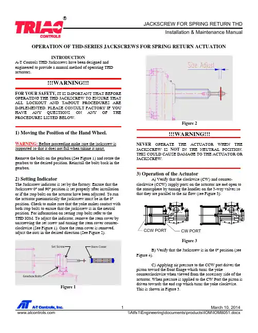
Installation & Maintenance ManualOPERATION OF THD-SERIES JACKSCREWS FOR SPRING RETURN ACTUATIONINTRODUCTIONA-T Controls THD Jackscrews have been designed and engineered to provide a manual method of operating THD actuators.FOR YOUR SAFETY, IT IS IMPORTANT THAT BEFORE OPERATING THE THD JACKSCREW TO ENSURE THAT ALL LOCKOUT AND TAGOUT PROCEDURES ARE IMPLEMENTED. PLEASE CONSULT FACTORY IF YOU HAVE ANY QUESTIONS ON ANY OF THE PROCEDURES LISTED BELOW.1) Moving the Position of the Hand Wheel.WARNING: Before proceeding make sure the jackscrew is supported so that it does not fall when taking it apart.Remove the bolts on the gearbox (See Figure 1) and rotate the gearbox to the desired position. Reinstall the bolts back in the gearbox.2) Setting IndicatorThe Jackscrew indicator is set by the factory. Ensure that the Jackscrew 0º and 90º position is set properly after installation or if the stop bolts on the actuator have been adjusted. To run the actuator pneumatically the jackscrew must be in the 0º position. Check to make sure that the yoke makes contact with both stop bolts to ensure that the jackscrew is in the neutral position. For information on setting stop bolts refer to the THD IOM. To adjust the indicator, remove the stem cover by unscrewing the set screw and turning the stem cover counter-clockwise (See Figure 1). Once the stem cover is removed, adjust the nuts in the desired direction (See Figure 2).Figure 1Figure 2NEVER OPERATE THE ACTUATOR WHEN THE JACKSCREW IS NOT IN THE NEUTRAL POSITION. THIS COULD CAUSE DAMAGE TO THE ACTUATOR OR JACKSCREW.3) Operation of the Actuator A) Verify that the clockwise (CW) and counter-clockwise (CCW) supply ports on the actuator are not open to the atmosphere by turning the handles on the 3-way valves so that they are parallel to the air flow (see Figure 3).Figure 3B) Verify that the Jackscrew is in the 0º position (seeFigure 4).C) Applying air pressure to the CCW port drives the piston toward the front flange which turns the yokecounterclockwise when viewed from the accessory side of the actuator. When pressure is applied to the CW Port the piston is driven towards the end cap which turns the yoke clockwise. This is shown in Figure 3.Installation & Maintenance Manual4) Operation of JackscrewA) Verify that the clockwise and counter-clockwise supply ports on the actuator are open to the atmosphere by turning the handles on the 3-way valves so that they are perpendicular to the air flow (see Figure 3).B) To turn the valve in the clockwise direction, turn the hand wheel in the clockwise direction. To turn the valve in the counter-clockwise direction, turn the hand wheel counter-clockwise.C) Be sure before going back to pneumatic operation that the Jackscrew is set in the 0º position and both block and bleed valves are not open to the atmosphere.A-T Controls product, when properly selected, is designed to perform its intended function safely during its useful life. However, the purchaser or user of A-T Controls products should be aware that A-T Controls products might be used in numerous applications under a wide variety of industrial service conditions. Although A-T Controls can provide general guidelines, it cannot provide specific data and warnings for all possible applications. The purchaser / user must therefore assume the ultimate responsibility for the proper sizing and selection, installation, operation, and maintenance of A-T Controls products. The user should read and understand the installation operation maintenance (IOM) instructions included with the product, and train its employees and contractors in the safe use of A-T Controls products in connection with the specific application.While the information and specifications contained in this literature are believed to be accurate, they are supplied for informative purposes only. Because A-T Controls is continually improving and upgrading its product design, the specifications, dimensions and information contained in this literature are subject to change without notice. Should any question arise concerning these specifications, the purchaser/user should contact A-T Controls.For product specifications go to /A-T Controls, Inc. • 9955 International Boulevard, Cincinnati, OH 45246 • Phone: (513) 530-5175 • Fax: (513) 247-5462 • 。

生物颗粒燃料熔炼炉使用维护、保养说明书Operation and Maintenance Instruction of Bio-mass Pellet FuelSmelting Furnace泰州杰利瑞节能科技发展有限公司Taizhou Jie Lirui Energy Technology Development Co., Ltd敬告!Attention!请用户使用前详细阅读产品使用维护、保养说明书,并请在使用过程中严格遵循产品使用维护、保养说明书,若由用户使用不当引起的损坏制造商将不承担责任,碳化硅石墨坩埚属易耗件,不在质保范围。
Please read the product operation and maintenance instruction carefully before use, and strictly follow the product operation and maintenance instruction during the operation. In case of any damage caused by improper use, the manufacturer will not be liable; the silicon carbide graphite crucible is subject to vulnerable part and excluded in the warranty scope.精品文档目录Catalog1 概述Introduction2 组成Components3 主要技术参数Main technical parameters4 主要用途及适用范围Main applications and applicable scopes5 配电要求Power distribution requirements6 安装Installation7 启动前检查Check before start-up8 烘炉Dry-off operation for furnace9 使用与维护Operation and maintenance10 碳化硅石墨坩埚使用注意事项Precautions for using silicon carbide graphite crucible11 常见故障与排除Common faults and troubleshooting12 运输及开箱检查Transportation and out-of-box inspection13 技术支持Technical support 1 概述Introduction生物颗粒燃料熔炼炉(以下简称“熔炼炉”)采用半气化复合燃烧技术,具有低碳环保、高效节能、操作维护简单的特点,是替代燃油炉、燃气炉、焦碳炉、电炉的最佳产品,可以降低30%~60%的能耗成本。
生物颗粒燃料熔炼炉使用维护、保养说明书Operation and Maintenance Instruction of Bio-mass Pellet FuelSmelting Furnace泰州杰利瑞节能科技发展有限公司Taizhou Jie Lirui Energy Technology Development Co., Ltd敬告!Attention!请用户使用前详细阅读产品使用维护、保养说明书,并请在使用过程中严格遵循产品使用维护、保养说明书,若由用户使用不当引起的损坏制造商将不承担责任,碳化硅石墨坩埚属易耗件,不在质保范围。
Please read the product operation and maintenance instruction carefully before use, and strictly follow the product operation and maintenance instruction during the operation. In case of any damage caused by improper use, the manufacturer will not be liable; the silicon carbide graphite crucible is subject to vulnerable part and excluded in the warranty scope.目录Catalog1 概述Introduction2 组成Components3 主要技术参数Main technical parameters4 主要用途及适用范围Main applications and applicable scopes5 配电要求Power distribution requirements6 安装Installation7 启动前检查Check before start-up8 烘炉Dry-off operation for furnace9 使用与维护Operation and maintenance10 碳化硅石墨坩埚使用注意事项Precautions for using silicon carbide graphite crucible11 常见故障与排除Common faults and troubleshooting12 运输及开箱检查Transportation and out-of-box inspection13 技术支持Technical support 1 概述Introduction生物颗粒燃料熔炼炉(以下简称“熔炼炉”)采用半气化复合燃烧技术,具有低碳环保、高效节能、操作维护简单的特点,是替代燃油炉、燃气炉、焦碳炉、电炉的最佳产品,可以降低30%~60%的能耗成本。
GETTING STARTED GUIDENI USB-7846RR Series for USB Multifunction RIO with Kintex-7 160T FPGA Français Deutsch日本語한국어简体中文/manualsThis document explains how to install and configure National Instruments USB-7846R.Safety GuidelinesCaution Do not operate the NI USB-7846R in a manner not specified in this usermanual. Product misuse can result in a hazard. You can compromise the safetyprotection built into the product if the product is damaged in any way. If the productis damaged, return it to National Instruments for repair.Electromagnetic Compatibility GuidelinesThis product was tested and complies with the regulatory requirements and limits for electromagnetic compatibility (EMC) as stated in the product specifications. These requirements and limits are designed to provide reasonable protection against harmful interference when the product is operated in its intended operational electromagnetic environment.This product is intended for use in residential, commercial, and industrial locations. However, harmful interference may occur in some installations or when the product is connected to a peripheral device or a test object. To minimize interference with radio and television reception and prevent unacceptable performance degradation, install and use this product in strict accordance with the instructions in the product documentation.Furthermore, any changes or modifications to the product not expressly approved by National Instruments could void your authority to operate it under your local regulatory rules.Caution To ensure the specified EMC performance, you must install the includedsnap-on ferrite bead onto the DC power cord of the power supply as described in thisdocument.Caution To ensure the specified EMC performance, operate this product only withshielded cables and accessories.Unpacking the KitCaution To prevent electrostatic discharge from damaging the device, groundyourself using a grounding strap or by holding a grounded object, such as your computer chassis.1.Touch the antistatic package to a metal part of the computer chassis.2.Remove the device from the package and inspect the device for loose components or anyother sign of damage.Caution Never touch the exposed pins of connectors.Notify NI if the device appears damaged in any way. Do not install a damaged device.3.Unpack any other items and documentation from the kit.Store the device in the antistatic package when the device is not in use.Verifying the Kit ContentsVerify that the following components are in your kit.Figure 1.Kit Contents for the NI USB-7846R1.ModuleB Cable3.Ferrite Bead4.NI-RIO Media5.Power Supply6.Getting Started Guide2 | | NI USB-7846R Getting Started GuideInstalling SoftwareYou must be an Administrator to install NI software and devices on your computer. Before connecting the hardware, install the software in the following order.1.Install the driver software using either the media included in your kit or by downloadingthe latest version from /downloads.2.Follow the instructions in the installation prompts.a)Windows 8/7/Vista users may see access and security messages during installation.Accept the prompts to complete the installation.3.When the installer completes, a dialog box asks if you want to restart, shut down, orrestart later. Select Restart .Installing the HardwareConnecting the USB CableUSB modules can be connected directly to the host PC, to a powered USB hub, or to an NI PXI or PXI Express chassis featuring a USB port.1.Connect the USB cable to the NI USB-7846R using the cable device port.2.Connect the other end of the USB cable to the host PC, powered hub, or chassis.e the jackscrew on the locking USB cable to securely attach the cable to the NIUSB-7846R.Powering the ModuleCaution To ensure the specified EMC performance, install the included snap-onferrite bead onto the DC power cord of the power supply in accordance with theinstructions provided.1.Install the ferrite bead by opening the housing and looping the power supply once throughthe center of the bead. Ensure the ferrite bead is as close to the end of the cable aspractical.2.Close the ferrite bead until the locking tabs engage securely.NI USB-7846R Getting Started Guide| © National Instruments| 3Figure 2. Installing the Ferrite Bead1.Power Supply2.Ferrite3.Connect the power supply to the NI USB-7846R.4.Connect the other end of the power supply to a user-supplied power cord.5.Connect the user-supplied power cord to the appropriate power source.6.Turn the power switch on the NI USB-7846R to the on position.USB Device Security Cable SlotThe security cable slot allows you to attach an optional laptop lock to your NI USB-7846R.Note The security cable is designed to act as a deterrent, but might not prevent thedevice from being mishandled or stolen. For more information, refer to thedocumentation that accompanied the security cable.Note The security cable slot on the USB device might not be compatible with alllaptop lock cables.Refer to the documentation that accompanied the security cable for installation instructions.Verifying Hardware InstallationYou can verify that the system recognizes the USB device by using Measurement &Automation Explorer (MAX).unch MAX by navigating to Start »All Programs »National Instruments »MAX or byclicking the MAX desktop icon.2.Expand Devices and Interfaces .3.Verify that the device appears under USB Devices .If the device does not appear, press <F5> to refresh the view in MAX. If the device does not appear after refreshing the view, visit /support for troubleshooting information.4 | | NI USB-7846R Getting Started GuideConnecting SignalsThe following figure shows the I/O connector pin assignments and locations for the NIUSB-7846R.Caution To ensure the specified EMC performance, operate this product onlywith shielded cables and accessories.Note NI is not liable for connections that exceed any of the maximum ratingsof input or output signals on the NI USB-7846R and on the computer chassis.For the maximum input and output ratings for each signal, refer to the NI USB-7846R Specifications , available at /manuals.Figure 3. NI USB-7846R Connector Pin Assignments and LocationsCONNECTOR 0(DIO)CONNECTOR 1(MIO)The +5 V terminals on the I/O connector supply +5 V referenced to GND. Use these terminals to power external circuitry. The NI USB-7846R is protected from overvoltage and overcurrentNI USB-7846R Getting Started Guide | © National Instruments | 5conditions. Refer to the NI USB-7846R User Manual, available at /manuals, for more information.Where to Go NextRefer to the following figure for information about other product tasks and associated resources for those tasks.Worldwide Support and ServicesThe National Instruments website is your complete resource for technical support. At / support, you have access to everything from troubleshooting and application development self-help resources to email and phone assistance from NI Application Engineers.6| | NI USB-7846R Getting Started GuideVisit /services for NI Factory Installation Services, repairs, extended warranty, and other services.Visit /register to register your National Instruments product. Product registration facilitates technical support and ensures that you receive important information updates from NI.National Instruments corporate headquarters is located at 11500 North Mopac Expressway, Austin, Texas, 78759-3504. National Instruments also has offices located around the world. For telephone support in the United States, create your service request at /support or dial 1 866 ASK MYNI (275 6964). For telephone support outside the United States, visit the Worldwide Offices section of /niglobal to access the branch office websites, which provide up-to-date contact information, support phone numbers, email addresses, and current events.NI USB-7846R Getting Started Guide| © National Instruments| 7Refer to the NI Trademarks and Logo Guidelines at /trademarks for information on National Instruments trademarks. Other product and company names mentioned herein are trademarks or trade names of their respective companies. For patents covering National Instruments products/technology, refer to the appropriate location: Help»Patents in your software, the patents.txt file on your media, or the National Instruments Patent Notice at /patents. You can find information about end-user license agreements (EULAs) and third-party legal notices in the readme file for your NI product. Refer to the ExportCompliance Information at /legal/export-compliance for the National Instruments global trade compliance policy and how to obtain relevant HTS codes, ECCNs, and other import/export data.© 2014 National Instruments. All rights reserved.376846A-01Mar14。
操作说明手册的封面内容翻译(中英文对照):Multi-turn actuators万向驱动装置(产品型号)SAR (产品型号)AUMA NORM (AUMA是这个阀门生产厂的品牌名称)AUMA标准Operation instructions (操作手册)目录内容:Scope of these instructions:本手册内容介绍的范围包括:These instructions are valid for multi-turn actuators for Open-close duty, SA ,and multi-turn actuators for modulating duty, .本手册的说明适应型号为SA 、具有开启-关闭功能系列的万向驱动装置和型号为、具有调节功能系列的万向驱动装置有效。
These operations instructions are only valid for “clockwise closing”, . driven shaft turns clockwise to close the valve.这些操作说明只对"顺时针关闭"有效,即:驱动轴顺时针转动关闭阀门。
.Safety instructions (安全说明 )Range of application (应用的范围 ) AUMQ multi-turn actuators are designed for the operation of industrial valves, , globe valves, butterfly valves and ball valves. For other applications, please consult us. AUMA is not liable for any applications. Such risk lies entirely with the user. AUMQ万向驱动装置是为工业用阀所设计的,例如:工业生产常用球瓣阀,蝶阀和球阀。
FDA英文药品说明书规定项目中英对照--------------------------------------------------------------------------------药品说明书旧称description,instruction,direction.今称insert,package insert美国FDA规定其应包括十项。
一.drug names(药物名称)1.通常每种药物有三个名字(1)proprietary name(商品名称)(2)popular name(俗名)(3)chemical name(化学名)2.说明书标题多用商品名其右上角标有R者,表示registered trademark(注册商标)二.description(性状)(常用description,introduction,composition)包括药品的chemical structure(化学结构)、chemical composition(化学成分)、physical and chemical properties(物理和化学性质)三.clinical pharmacology(临床药理学)常用的还有:clinical data(临床数据)、clinical experience(临床经验)、clinical use(临床应用)、clinical observation(临床观察)、clinical effect(临床疗效)、clinical discussion(临床讨论)、mode of mechanism of action(临床机理及途径)、pharmacological actions(药理作用)、therapeutical actions(治疗作用)、bacteriology(细菌学)、microbiology(微生物学)、physiology(生理学)、toxicology(毒理学)四.indications and usage(适应证和用法)常用标题:indications,major indications,clinical indications,principal indications,condications,uses,treatment五.contraindications(禁忌证)1.常用标题contraindications,restriction on use(限制使用)2.常用词(组)pregnant women孕妇women of childbeating age育龄妇女be hypersensitive to 对......过敏者allergic reaction变态反应lactation,early infancy乳期heart,cardiac,myocardial心脏,心脏的,心肌的kidney,renal肾,肾脏的liver,hepatic肝,肝脏的insufficiency,impairment机能不全damage,danger,failure损伤,危险,衰?BR>六.precautions(注意事项)常用标题:causions,remark,note,notice,attention,awakening, N.B.七.warnings(警告)常用标题:additional warnings(告戒事项)八.adverse reactions(不良反应)常用标题:side reaction(副反应)、untoward reaction(不良反应)、toxicity reaction(毒性反应)、anaphylactic reaction(过敏反应)、side effects,by-effects,after effects,undesirable effects(副作用)、double infection(双重感染)九.overdosage(用药过量)常用标题:treatment of overdosage(用药过量的治疗)十.dosage and administration(剂量用法)1.常用标题:administration procedure,method for administration,method of use,direction for use,how to use,recommendation,reconstitution(用法)posology,dosage(剂量)application and dosage,usage and dosage(用法与剂量)clinical application(临床应用)2.mode of administration(给药方式)intramuscularly肌肉注射intragluteally臀肌注射intraarterially动脉注射intravenously静脉注射intrathecally鞘内注射intracerebeospinally脑脊髓腔注射orally口服parentarally肠道外给药locally局部给药subconjunctivally结膜下给药sublingually舌下给药submucously黏膜下给药现各大药厂的说明书,项目远远超过十项,如:1.animal pharmacology and animal toxicology(动物药理学和动物毒理学)2.absorption and excretion(吸收和排泄)3.tolerance(耐受性)4.drug interactions(药物相互作用)5.storage and duration of efficacy(贮藏与失效期)6.packages(包装)7.advantages(优点)8.references(参考文献)9.further information(补充说明)10.manufacturer(生产者)。
SIMOCODE pro ReadmeProgramming and Operating Manual 02/2021Legal informationWarning notice systemThis manual contains notices you have to observe in order to ensure your personal safety, as well as to prevent damageto property. The notices referring to your personal safety are highlighted in the manual by a safety alert symbol, noticesreferring only to property damage have no safety alert symbol. These notices shown below are graded according tothe degree of danger.DANGERindicates that death or severe personal injuryWARNINGindicates that death or severe personal injury may result if proper precautions are not taken.CAUTIONindicates that minor personal injury can result if proper precautions are not taken.NOTICEindicates that property damage can result if proper precautions are not taken.If more than one degree of danger is present, the warning notice representing the highest degree of danger will beused. A notice warning of injury to persons with a safety alert symbol may also include a warning relating to propertydamage.Qualified PersonnelThe product/system described in this documentation may be operated only bypersonnel qualified for the specific task in accordance with the relevant documentation, in particular its warning notices and safety instructions.Qualified personnel are those who, based on their training and experience, are capable of identifying risks andavoiding potential hazards when working with these products/systems.Proper use of Siemens productsNote the following:WARNINGSiemens products may only be used for the applications described in the catalog and in the relevant technicaldocumentation. If products and components from other manufacturers are used, these must be recommended orapproved by Siemens. Proper transport, storage, installation, assembly, commissioning, operation and maintenanceare required to ensure that the products operate safely and without any problems. The permissible ambientconditions must be complied with. The information in the relevant documentation must be observed. TrademarksAll names identified by ® are registered trademarks of Siemens AG. The remaining trademarks in this publication maybe trademarks whose use by third parties for their own purposes could violate the rights of the owner. Disclaimer of LiabilityWe have reviewed the contents of this publication to ensure consistency with the hardware and software described.Since variance cannot be precluded entirely, we cannot guarantee full consistency. However, the information in thispublication is reviewed regularly and any necessary corrections are included in subsequent editions.Siemens AGSmart InfrastructureElectrical ProductsPostfach 10 09 5393009 RegensburgGERMANYⓅ 01/2021 Subject to changeCopyright © Siemens AG 2019.All rights reservedTable of contents1Security information (5)2Information on data protection (7)3Validity (9)4Improvements in SIMOCODE ES (11)4.1Improvements and changes in SIMOCODE ES V16 Update 2 (11)ReadmeProgramming and Operating Manual, 02/20213Table of contentsReadme 4Programming and Operating Manual, 02/2021Security information1Siemens provides products and solutions with industrial security functions that support thesecure operation of plants, systems, machines, and networks.In order to protect plants, systems, machines and networks against cyber threats, it is necessaryto implement – and continuously maintain – a holistic, state-of-the-art industrial securityconcept. Siemens’ products and solutions form one element of such a concept.Customers are responsible for preventing unauthorized access to their plants, systems,machines and networks. These systems, machines and components should only be connectedto the enterprise network or the Internet if and only to the extent necessary and with appropriatesecurity measures (firewalls and/or network segmentation) in place.You can find more information on protective measures in the area of industrial security byvisiting:https:///industrialsecurity.Siemens’ products and solutions undergo continuous development to make them more secure.Siemens strongly recommends performing product updates as soon as they are available andusing only the latest product versions. Use of product versions that are no longer supported, andfailure to apply latest updates may increase customer’s exposure to cyber threats.To stay informed about product updates, subscribe to the Siemens Industrial Security RSS Feedunderhttps:///industrialsecurity.ReadmeProgramming and Operating Manual, 02/20215Security informationReadme 6Programming and Operating Manual, 02/2021Information on data protection2Siemens observes standard data protection principles, in particular the principle of privacy bydesign.For SIMOCODE ES this means:SIMOCODE ES does not process or store any personal data, only technical function data (e.g.time stamps). If you link this data with other data (e.g. shift schedules) or store personal data onthe same storage medium (e.g. hard disk), and thus establish a link to a person or persons, thenyou are responsible for ensuring compliance with the relevant data protection regulations.ReadmeProgramming and Operating Manual, 02/20217Information on data protectionReadme 8Programming and Operating Manual, 02/2021Validity3This update is valid for the following products:•SIMOCODE ES V16 Basic•SIMOCODE ES V16 ProfessionalReadmeProgramming and Operating Manual, 02/20219ValidityReadme 10Programming and Operating Manual, 02/2021Improvements in SIMOCODE ES4 4.1Improvements and changes in SIMOCODE ES V16 Update 2•Following selection of a soft starter application in the SIRIUS device wizard, the correct default values are now specified.•The button for counter-clockwise rotation is no longer displayed in the commissioning editor under "Control/status information" for the "Direct starter" control function.•In the chart editor, the function block "Operator panel with display" is now available in the function catalog.•After the parameter assignment of a SIMOCODE pro V MR device has been uploaded, the parameters "Monitoring functions → ground fault → internal ground fault" are read outcorrectly.•Online access via the COM interface [SIRIUS PtP] is fully available again.•Problems that could occur after migration of SIMOCODE pro V PN devices have beeneliminated.•In the expert list of the parameter editor, the IP address can be edited in the offline mode.•Problems that could occur in connection with the activation of the transformation ratio in the parameter editor under "Motor protection → overload/asymmetry/blocking → set current"have been cleared.•Empty fields for the user name and password of the web server are no longer output during printing.•Incomplete entries in the error buffer/error log of the commissioning editor are nowdisplayed in full.•Improvements to the user interface texts and tooltips•The stability when working with the TIA Portal has been improved, among other things based on feedback from returned crash reports.ReadmeProgramming and Operating Manual, 02/202111Improvements in SIMOCODE ES4.1 Improvements and changes in SIMOCODE ES V16 Update 2Readme 12Programming and Operating Manual, 02/2021。