1807中文说明书简易操作手册
- 格式:doc
- 大小:26.00 KB
- 文档页数:2

自动识别系统JHS-180 中文操作说明书目录1 1.1 1.22 2.1 2.1.1 2.1.2 2.2 2.2.1 2.3 2.3.1 2.3.23 3.1 3.1.1 3.1.2 3.1.3 3.1.4 3.1.5 3.2 3.2.1 3.2.2 3.2.3 3.2.4 3.3 3.3.1 3.3.2 3.3.3 3.3.4 部件名称和功能--------------------------------------------------------------------操作面板-----------------------------------------------------------------------------显示-----------------------------------------------------------------------------------基本操作-------------------------------------------------------------------------------开电源----------------------------------------------------------------------------------他船清单-------------------------------------------------------------------------------他船详细清单-------------------------------------------------------------------------关电源----------------------------------------------------------------------------------关显示----------------------------------------------------------------------------------报警-------------------------------------------------------------------------------------警戒区报警----------------------------------------------------------------------------消失目标警报-------------------------------------------------------------------------主菜单----------------------------------------------------------------------------------信息菜单-------------------------------------------------------------------------------编辑与发射----------------------------------------------------------------------------发射屏----------------------------------------------------------------------------------接收屏----------------------------------------------------------------------------------查询-------------------------------------------------------------------------------------长度范围信息-------------------------------------------------------------------------目的地设置----------------------------------------------------------------------------目的地----------------------------------------------------------------------------------航点-------------------------------------------------------------------------------------估计到达时间-------------------------------------------------------------------------航点-------------------------------------------------------------------------------------航行信息设置-------------------------------------------------------------------------航行状况信息-------------------------------------------------------------------------在船人员-------------------------------------------------------------------------------船舶和货物类型----------------------------------------------------------------------吃水深度-------------------------------------------------------------------------------11222233444455589911121213141415161616173.3.5 3.4 3.4.1 3.4.2 3.5 3.5.1 3.5.2 3.6 3.6.1 3.6.2 3.6.3 3.6.4 3.6.5 3.6.6 3.7 3.7.1 3.7.2 3.7.3 3.7.4 3.7.5 3.7.6 龙骨以上高度------------------------------------------------------------------------报警设置-------------------------------------------------------------------------------距离-------------------------------------------------------------------------------------消失物标------------------------------------------------------------------------------船队设置-------------------------------------------------------------------------------船名------------------------------------------------------------------------------------- MMSI(船舶移动识别码)-----------------------------------------------------------设置菜单-------------------------------------------------------------------------------密码设置-------------------------------------------------------------------------------信道处理设置-------------------------------------------------------------------------本船数据显示设置-------------------------------------------------------------------长距离应答设置----------------------------------------------------------------------对比度设置----------------------------------------------------------------------------重发号码设置-------------------------------------------------------------------------维护菜单-------------------------------------------------------------------------------收发状况对数显示-------------------------------------------------------------------自动识别系统报警显示-------------------------------------------------------------传感器状况显示----------------------------------------------------------------------电源开/关对数显示-------------------------------------------------------------------发射关对数显示----------------------------------------------------------------------软件版本显示-------------------------------------------------------------------------1718181818191920202123242425252526262728281.部件名称与功能1.1 操作面板(1)LCD面板更多信息参考“1.2显示”。
YAESU Fm Transceiver FT-1807M简易操作手册1、在主机安装完毕后,按住(PWR)键三秒开机,完成后,在显示VFO(446.000)的情况下可以进行你需要的任何一项操作。
2、设置手动自动下差:在显示VFO的模式下按住(MHZ SET)键三秒进入主菜单,旋动(DIAL)旋纽到第四项菜单(ARS),轻按(MHZ SET)键进入第四项主菜单选择开关手动自动下差(ON/OFF),设置完毕后轻按(MHZ SET)键退出菜单。
3、设置差频:在显示VFO模式下按住(MHZ SET)键三秒进入主菜单,旋动(DIAL)旋纽到第43项(RPT)菜单,轻按(MHZ SET)键进入此项菜单设置上下差频(-RPT,+RPT,OFF)4、设置差频数值:在显示VFO模式下按住(MHZ SET)键三秒进入主菜单,旋动(DIAL)旋纽到第46项(SHIFL)菜单,轻按(MHZ SET)键进入此项菜单后(7.6MHZ)设置差频值,机器默认数值为7.6MHZ,旋动(DIAL)旋纽设置你需要的差频值,设置完毕后轻按(MHZ SET)键推出主菜单。
5、设置亚音编码:在显示VFO模式下按住(MHZ SET)键三秒进入主菜单,旋动(DIAL)旋纽到第49项(SQLTYP)菜单,轻按(MHZ SET)键进入此项菜单设置你需要的编码,一般选择(TONE)编码(TONE/TSQL/DCS/RVTN/OFF) 6、设置亚音数值:在显示VFO模式下按住(MHZ SET)键三秒进入主菜单,旋动(DIAL)旋纽到第52项()菜单,轻按(MHZ SET)键进入此项菜单后(100MHZ)设置亚音,旋动(DIAL)旋纽进行设置你需要的亚音值。
7、储存频道:在显示VFO的模式下,用手咪输入你想要的频点,然后按住(MWD/MR)键,直至屏幕右下角出现数字(0),如果此数字一直在闪烁,表示此频道为空,然后旋动(DIAL)纽选择频道号码,选定后轻按(MW D/RW)键,完成频道存储。
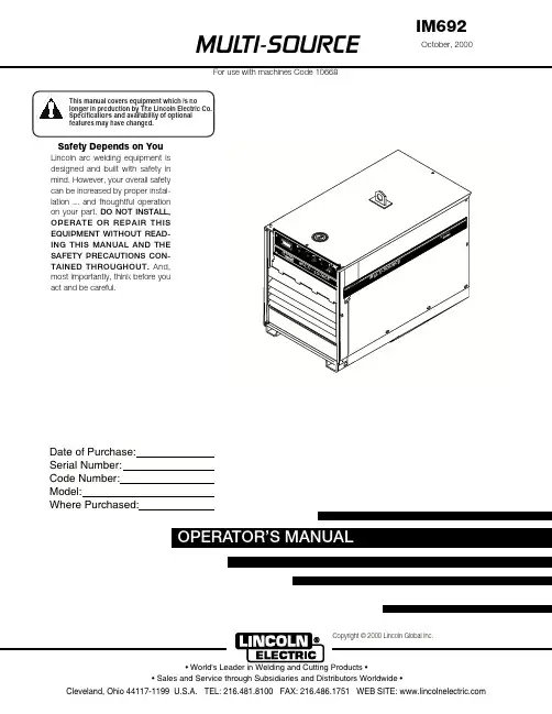
MUL TI-SOURCEOPERATOR’S MANUALFor use with machines Code 10668October, 2000IM692Safety Depends on YouLinco ln arc welding equipment is designed and built with safety in mind. However, your overall safety can be increased by proper instal-latio n ... and tho ughtful o peratio n on your part.DO NOT INSTALL,OPERATE OR REPAIR THIS EQUIPMENT WITHOUT READ-ING THIS MANUAL AND THE SAFETY PRECAUTIONS CON-TAINED THROUGHOUT.And,most importantly, think before you act and be careful.Copyright © 2000 Lincoln Global Inc.This manual covers equipment which is nolonger in production by The Lincoln Electric Co. Speci cations and availability of optional features may have changed.Mar ‘95Mar ‘95Mar. ‘93for selecting a QUALITY product by Lincoln Electric. We want you to take pride in operating this Lincoln Electric Company product ••• as much pride as we have in bringing this product to you!Read this Operators Manual completely before attempting to use this equipment. Save this manual and keep it handy for quick reference. Pay particular attention to the safety instructions we have provided for your protection.The level of seriousness to be applied to each is explained below:vvOther indicator lights include the amber Thermal light that signals when the long term output current limit has been exceeded. This limit is determined by a ther-mostat sensing the temperature of the negative output lead from the secondary coils. The white Power light indicates when the Control board is energized. The three lights are high intensity LEDs for improved visi-bility in daylight.The Output Power display uses high intensity LEDs to indicate the percentage of full rated output the machine is supplying.Two additional thermostats protect the machine in the case of fan failure or blocked air flow. The SCR heat sink thermostat responds first to loss of air flow at nor-mal output loads. This thermostat will disable the machine output. The transformer iron rear thermostat senses that the lamination (and thus the coil insula-tion) is over heating (which can happen even if the output is disabled). This thermostat will interrupt power to the Control board causing the input contactor to open until the iron cools.The only user controls are an on-off toggle Power switch that energizes the machine and a 10 A circuit breaker protecting the fan auxiliary against short cir-cuits.DESIGN FEATURES - ALL MODELSSPECIFICATIONS,DESIG N FEATURES AND ADVANTAGESCase parts are predominantly stainless steel, the PC boards are potted in trays, the controls are sealed, all machine coils are copper and the whole transformer is varnish dipped to maximize environmental withstand capability. The coils are all conservatively rated for long life.The Multi-Source output regulates against wide changes in output loading and input line voltage varia-tions to supply a consistently stable voltage high enough to allow the Multi-Welds to provide good man-ual electrode capability.SAFETY PRECAUTIONSGENERAL DESCRIPTIONThe Multi-Source is designed to supply power to the Multi-Weld welders. It has a wide range three phase AC input and can be operated on 50 or 60 Hz. The Multi-Source output peak voltage regulates against wide changes in output loading and input line voltage variations to supply a consistently stable voltage high enough to allow the Multi-Welds to provide good man-ual electrode capability.Primary input voltage taps are selected by a single movable link on the reconnect panel. Main trans-former auxiliary windings power the firing circuit and fan motor. The control auxiliary transformer has a sin-gle, wide range primary and is not reconnectable.The Fan As Needed feature is activated by an output current of 20 Adc or a thermostat on the main trans-former iron.An independent safety circuit on the Control board monitors the voltage peaks and opens the input con-tactor if the limit is exceeded. The green Safe Output light indicates when the machine output voltage isFACTORY INSTALLED OPTIONS / ACCESSORIESThere are no factory installed options.FIELD INSTALLED OPTIONS / ACCESSORIESK1735-1 Multi-Weld 350, Multi-process controller.K857, K857-1 Remote Control, Control Multi-Weldremotely (25 or 100 ft.).K1736-1 Distribution Box, Connects up to 10 Multi-Welds.K449 LN-25, Across the arc wire feeder.K1788-1 Roll Cage, Protect power source, facilitate moving, store cable.K1806-1 Multi-Weld Four Pack, Mounting / lift rack for M-S and four M-Ws.K1807-1 Multi-Weld Eight Pack, Mounting / lift rack for M-S and eight M-Ws.S20428Paralleling Kit,Allows two machines toequally share double load.MACHINE CALIBRATION SPECIFICATIONThe Multi-Source digital display is controlled by a cur-rent sensing circuit on the Control board. The display reads 100 when machine output is a little over 40 kW. To recalibrate the display, the machine output may loaded with Multi-Weld welders or resistive grids or a combination of both to obtain an output of 533 Adc as read by a calibrated standard ammeter. Trimmer resistor R49 may be adjusted to cause the display to read 100.This Troubleshooting Guide is provided to help you locate and repair possible machine malfunctions.Simply follow the three-step procedure listed below.Step 1.LOCATE PROBLEM (SYMPTOM).Look under the column labeled “PROBLEM (SYMP-TOMS)”. This column describes possible symptoms that the machine may exhibit. Find the listing that best describes the symptom that the machine is exhibiting.Step 2.POSSIBLE CAUSE.The second column labeled “POSSIBLE CAUSE” liststhe obvious external possibilities that may contribute to the machine symptom.Step 3.RECOMMENDED COURSE OF ACTIONThis column provides a course of action for the Possible Cause, generally it states to contact your local Lincoln Authorized Field Service Facility.If you do not understand or are unable to perform the Recommended Course of Action safely, contact your local Lincoln Authorized Field Service Facility.HOW TO USE TROUBLESHOOTING GUIDEService and Repair should only be performed by Lincoln Electric Factory Trained Personnel.Unauthorized repairs performed on this equipment may result in danger to the technician and machine operator and will invalidate your factory warranty. For your safety and to avoid Electrical Shock, please observe all safety notes and precautions detailed throughout this manual.__________________________________________________________________________5. LEDs 1 through 6 indicate gate signals are being sent to the main SCRs 1 through 6 respectively. If LED2 on the Control board is bright, along with LEDs 7, 8, and 9 on Firing board, and LEDs 1through 6 are unequal in brightness, check to make sure lead 231 between Control board and Firing board is not broken. (If lead 231 is removed while the machine output is at open circuit, the output voltage peaks may be unregulated and cause the over-voltage protection circuit to open the input contactor. The over-voltage protection circuit may disabled by disconnecting lead 222D at the nega-tive output stud or at pin 1 of P2. NOTE: Themachine may not be used for welding with the pro-tection circuit disabled.6. If one or more of LEDs 1 through 6 are off, LEDs 7,8, and 9 are on and the voltage on lead 231 from the Control board (pin 13, P5 to pin 12, P5) is 3 to 13Vdc replace the Firing PCB.PC BOARD TROUBLESHOOTING GUIDE - FIRING P .C.BOARD1. LEDs 1 through 9 must be lit when the Multi-Source is turned on and the Control board is sending an enable signal to the Firing board (pin 7 in P8 is low in reference to common at pin 12 in P5).2. LEDs 7, 8, and 9 indicate AC power being supplied to the P.C. board from auxiliary windings on the main transformer (T1). If a LED is not on, turn the machine off and unplug P8 from the firing board.Turn the machine back on and check the following voltages:3. If all voltages are present, turn power off, and plug P5 back into J5. Turn power back on. If LEDs 7, 8or 9 are still not lit, replace Firing PCB.4. If voltages were not present, check the circuit back through the external dropping resistors to the auxil-iary windings for a possible open resistor or wire.PC BOARD TROUBLESHOOTING GUIDE - CONTROL P .C.BOARD1. The white Power light on the machine control panel indicates that the Control board power supply is being supplied by rectified secondary voltage from the Control transformer (T2) by way of the Power switch and transformer iron rear thermostat.2. LED1 indicates machine output voltage. At normal output voltages, LED1 will be brightly lit.3. LED2 indicates the level of the control signal to the Firing board. The brightness of LED2 is inversely proportional to machine output because the control signal increases as the machine output decreases.4. LED3 lights when the current amplifier senses an output current over about 10 amps and sends a sig-nal to turn the cooling fan on. If LED3 is on but the fan is not , there could be a problem with the fan motor or the fan motor drive circuit (see LED6).5. LED4 says that some signal, either thermostat, out-put current or output over-current is calling for the fan to operate.6. LED5 tells us that the current signal from the shunt is too high. If LED5 is lit for 5-8 seconds, the enable signal to the Firing board is made high to shut off the output SCRs. In the case of a short duration current overload, LED5 may only be briefly litbecause, in normal operation, the machine output immediately goes to zero. Once disabled, the out-put will remain off for about 75 seconds.7. LED6 indicates that the input to the fan motor opto triac driver has been energized. LED6 should be on as long as the fan motor runs. LED6 and the fan motor will be on for about 5 minutes after LED4goes off.8. LED7 will light when the shorted SCR circuit acti-vates. A positive voltage on the negative output stud (AC instead of DC on the output studs) will activate a circuit causing the input contactor to open. This circuit is active only when the enable signal to the Firing board is high (the output is off).The contactor will remain open (and the whitePower light will remain on) until the Power switch is turned off (or the input power to the machine is oth-erwise removed) for about 1 second and then turned on again.9. The green Safe Output light on the control panel when the machine output voltage is present and safe. It lights when the machine output is between 40 Vdc and 113 volts peak. 10. The yellow Thermal light on the front panel lightswhen the open thermostat signal is sent to the fan control and output disable circuits.Now Available...12th EditionThe Procedure Handbook of Arc WeldingWith over 500,000 copies of previous editions published since 1933, the Procedure Handbook is considered by many to be the “Bible” of the arc welding industry.This printing will go fast so don’t delay. Place your order now using the coupon below.The hardbound book contains over 750 pages of welding information, techniques and procedures. Much of this material has never been included in any other book.A must for all welders, supervisors, engineers and designers. Many welding instructors will want to use the book as a reference for all students by taking advantage of the low quantity discount prices which include shipping by 4th class parcel post.$15.00postage paid U.S.A. MainlandHow To Read Shop DrawingsThe book contains the latest information and application data on the American Welding Society Standard Welding Symbols. D etailed discussion tells how engineers and draftsmen use the “short-cut” language of symbols to pass on assembly and welding information to shop personnel.Practical exercises and examples develop the reader’s ability to visualize mechanically drawn objects as they will appear in their assembled form.187 pages with more than 100 illustrations. Size 8-1/2” x 11”Durable, cloth-covered board binding.$4.50postage paid U.S.A. MainlandNew Lessons in Arc WeldingLessons, simply written, cover manipulatory techniques;machine and electrode characteristics; related subjects,such as distortion; and supplemental information on arc welding applications, speeds and costs. Practice materials,exercises, questions and answers are suggested for each lesson.528 pages, well illustrated, 6” x 9” size, bound in simulated,gold embossed leather.$5.00postage paid U.S.A. MainlandNeed Welding Training?The Lincoln Electric Company operates the oldest and most respected Arc Welding School in the United States at its corporate headquarters in Cleveland, Ohio. Over 100,000stu-dents have graduated. Tuition is low and the training is “hands on”For details write:Lincoln Welding School 22801 St. Clair Ave.Cleveland, Ohio 44117-1199.and ask for bulletin ED-80 or call 216-383-2259 and ask for the Welding School Registrar.Lincoln Welding SchoolBASIC COURSE $700.005 weeks of fundamentalsThere is a 10%discount on all orders of $50.00 or more for shipment at one time to one location.Orders of $50 or less before discount or orders outside of North America must be prepaid with charge, check or money order in U.S. Funds Only.Prices include shipment by 4th Class Book Rate for U.S.A. Mainland Only.Please allow up to 4 weeks for delivery.UPS Shipping for North America Only.All prepaid orders that request UPS shipment please add:$5.00For order value up to $49.99$10.00For order value between $50.00 & $99.99$15.00For order value between $100.00 & $149.00For North America invoiced orders over $50.00 & credit card orders, if UPS is requested, it will be invoiced or charged to you at cost.Outside U.S.A. Mainland order must be prepaid in U.S. Funds. Please add $2.00 per book for surface mail or $15.00 per book for air parcel post shipment.METHOD OF PAYMENT:(Sorry, No C.O.D. Orders)CHECK ONE:Name:_______________________________________________Please Invoice (only if order is over $50.00)Address:_______________________________________________Check or Money Order Enclosed, U.S. Funds only _______________________________________________Credit Card - Telephone:_______________________________________________Signature as it appears on Charge Card:Account No.Exp Date|_|_||_|_|______________________Month YearUSE THIS FORM TO ORDER:Order from:BOOK DIVISION, The Lincoln Electric Company, 22801 St. Clair Avenue, Cleveland, Ohio 44117-1199BOOKS OR FREE INFORMATIVE CATALOGS Telephone: 216-383-2211 or, for fastest service, FAX this completed form to: 216-361-5901.Lincoln Welding School Titles:Price Code QuantityCost(ED-80)New Lessons in Arc Welding $5.00L Seminar Information Procedure Handbook “Twelfth Edition”$15.00PH (ED-45)How to Read Shop Drawings $4.50H Educational Video Information Incentive Management $5.00IM (ED-93) A New Approach to Industrial Economics $5.00NA James F. Lincoln Arc Welding The American Century of John C. Lincoln $5.00AC Foundation Book Information Welding Preheat Calculator $3.00WC-8(JFLF-515)Pipe Welding Charts $4.50ED-89SUB TOTALAdditional Shipping Costs if anyJapaneseChineseKoreanArabicREAD AND UNDERSTAND THE MANUFACTURER’S INSTRUCTION FOR THIS EQUIPMENT AND THE CONSUMABLES TO BE USED AND FOLLOW YOUR EMPLOYER’S SAFETY PRACTICES.SE RECOMIENDA LEER Y ENTENDER LAS INSTRUCCIONES DEL FABRICANTE PARA EL USO DE ESTE EQUIPO Y LOS CONSUMIBLES QUE VA A UTILIZAR, SIGA LAS MEDIDAS DE SEGURIDAD DE SU SUPERVISOR.LISEZ ET COMPRENEZ LES INSTRUCTIONS DU FABRICANT EN CE QUI REGARDE CET EQUIPMENT ET LES PRODUITS A ETRE EMPLOYES ET SUIVEZ LES PROCEDURES DE SECURITE DE VOTRE EMPLOYEUR.LESEN SIE UND BEFOLGEN SIE DIE BETRIEBSANLEITUNG DER ANLAGE UND DEN ELEKTRODENEINSATZ DES HER-STELLERS. DIE UNFALLVERHÜTUNGSVORSCHRIFTEN DES ARBEITGEBERS SIND EBENFALLS ZU BEACHTEN.JapaneseChineseKoreanArabicLEIA E COMPREENDA AS INSTRUÇÕES DO FABRICANTE PARA ESTE EQUIPAMENTO E AS PARTES DE USO, E SIGA AS PRÁTICAS DE SEGURANÇA DO EMPREGADOR.。


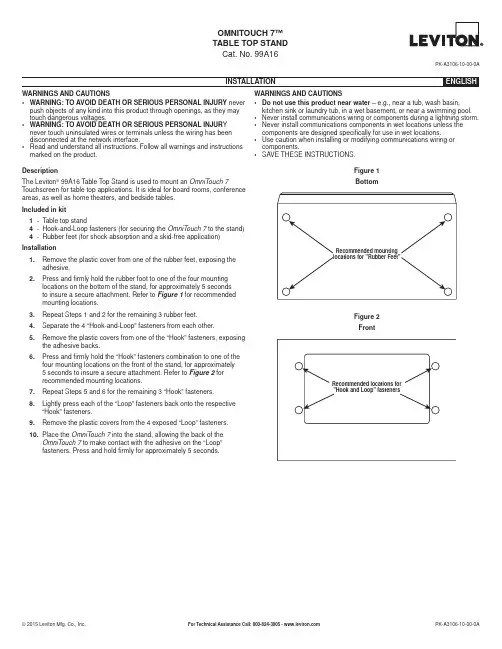
OMNITOUCH 7™TABLE TOP STANDCat. No. 99A16PK-A3106-10-00-0AWARNINGS AND CAUTIONS• W ARNING: TO AVOID DEATH OR SERIOUS PERSONAL INJURY never push objects of any kind into this product through openings, as they may touch dangerous voltages.• W ARNING: TO AVOID DEATH OR SERIOUS PERSONAL INJUR Y never touch uninsulated wires or terminals unless the wiring has been disconnected at the network interface.• R ead and understand all instructions. Follow all warnings and instructions marked on the product.WARNINGS AND CAUTIONS• D o not use this product near water – e.g., near a tub, wash basin, kitchen sink or laundry tub, in a wet basement, or near a swimming pool.• N ever install communications wiring or components during a lightning storm.• N ever install communications components in wet locations unless the components are designed specifically for use in wet locations.• U se caution when installing or modifying communications wiring or components.• S AVE THESE INSTRUCTIONS.DescriptionThe Leviton® 99A16 Table Top Stand is used to mount an OmniTouch 7 Touchscreen for table top applications. It is ideal for board rooms, conference areas, as well as home theaters, and bedside tables.Included in kit1 - Table top stand4 - Hook-and-Loop fasteners (for securing the OmniTouch 7 to the stand)4 - Rubber feet (for shock absorption and a skid-free application) Installation1.R emove the plastic cover from one of the rubber feet, exposing theadhesive.2.P ress and firmly hold the rubber foot to one of the four mountinglocations on the bottom of the stand, for approximately 5 secondsto insure a secure attachment. Refer to Figure 1 for recommendedmounting locations.3.R epeat Steps 1 and 2 for the remaining 3 rubber feet.4.S eparate the 4 “Hook-and-Loop” fasteners from each other.5.R emove the plastic covers from one of the “Hook” fasteners, exposingthe adhesive backs.6. P ress and firmly hold the “Hook” fasteners combination to one of thefour mounting locations on the front of the stand, for approximately5 seconds to insure a secure attachment. Refer to Figure 2 forrecommended mounting locations.7. R epeat Steps 5 and 6 for the remaining 3 “Hook” fasteners.8.L ightly press each of the “Loop” fasteners back onto the respective“Hook” fasteners.9.R emove the plastic covers from the 4 exposed “Loop” fasteners.10.P lace the OmniTouch 7 into the stand, allowing the back of theOmniTouch 7 to make contact with the adhesive on the “Loop”fasteners. Press and hold firmly for approximately 5 seconds.Figure 1 BottomFigure 2 FrontCOPYRIGHT AND TRADEMARK INFORMATIONThis document and all its contents herein are subject to and protected by international copyright and other intellectual property rights and are the property of Leviton Manufacturing Co., Inc, its subsidiaries, affiliates and/or licensors. Use herein of third party trademarks, service marks, trade names, brand names and/or product names are for informational purposes only, are/may be the trademarks of their respective owners; such use is not meant to imply affiliation, sponsorship, or endorsement. No part of this document may be reproduced, transmitted or transcribed without the express written permission of Leviton Manufacturing Co., Inc.FOR CANADA ONLYFor warranty information and/or product returns, residents of Canada should contact Leviton in writing at Leviton Manufacturing of Canada Ltd to the attention of the Quality Assurance Department, 165 Hymus Blvd, Pointe-Claire (Quebec), Canada H9R 1E9 or by telephone at 1 800 405-5320.LEVITON LIMITED WARRANTYLeviton warrants to the original consumer purchaser and not for the benefit of anyone else that products manufactured by Leviton under the Leviton brand name (“Product”) will be free from defects in material and workmanship for the time periods indicated below, whichever is shorter: • OmniPro II and Lumina Pro: three (3) years from installation or 42 months from manufacture date. • Omni LTe, Omni IIe, and Lumina: two (2) years from installation or 30 months from manufacture date. • BitWise Controllers, Accessories: two (2) years from installation or 30 months from manufacture date. • Lumina Gateway Controllers: two (2) years from installation or 30 months from manufacture date. • Thermostats, Accessories: two (2) years from installation or 30 months from manufacture date. • Batteries: Rechargeable batteries in products are warranted for ninety (90) days from date of purchase. Note: Primary (non-rechargeable) batteries shipped in products are not warranted. Products with Windows®Operating Systems: During the warranty period, Leviton will restore corrupted operating systems to factory default at no charge, provided that the product has been used as originally intended. Installation of non-Leviton software or modification of the operating system voids this warranty. Leviton’s obligation under this Limited Warranty is limited to the repair or replacement, at Leviton’s option, of Product that fails due to defect in material or workmanship. Leviton reserves the right to replace product under this Limited Warranty with new or remanufactured product. Leviton will not be responsible for labor costs of removal or reinstallation of Product. The repaired or replaced product is then warranted under the terms of this Limited Warranty for the remainder of the Limited Warranty time period or ninety (90) days, whichever is longer. This Limited Warranty does not cover PC-based software products. Leviton is not responsible for conditions or applications beyond Leviton’s control. Leviton is not responsible for issues related to improper installation, including failure to follow written Installation and operation instructions, normal wear and tear, catastrophe, fault or negligence of the user or other problems external to the Product. To view complete warranty and instructions for returning product, please visit us at .。


CZ801电子皮带秤控制仪表使用说明书上 海 滇 驰 电 子 电 器 有 限 公 司目录第一章 前言 (4)1.1 声明 (4)1.2 概述 (4)1.3 使用环境 (4)1.4 电源 (4)第二章 仪表构成 (5)2.1 人机界面(触摸屏) (5)2.2 控制主板 (5)2.2.1 称重传感器输入 (5)2.2.2 速度传感器输入 (5)2.2.3 开关量输入 (5)2.2.4 开关量输出 (5)2.3 模拟量卡(选配) (6)2.4 通讯卡(选配) (6)第三章 控制仪表安装 (7)3.1 总述 (7)3.2 安装 (7)3.3 接线 (7)第四章 使用操作 (8)4.1 首页界面 (8)4.2 称量界面(主页) (9)4.3 仪表设置 (10)4.3.1 参数设置 (10)4.3.2 秤数据设置 (12)4.3.3 输入输出设置 (14)4.3.4 报警设置 (15)4.3.5 通讯打印 (16)4.4 校准 (17)4.4.1 手动建立测试周期(推荐) (17)4.4.2 自动建立测试周期 (18)4.4.3 零点校准 (19)4.4.4 挂码校准 (20)4.4.5 链码校准 (21)4.4.6 电子校准 (22)4.4.7 实物校准 (23)附录1 端子接线图 (24)附录2 数据设定记录 (25)第一章 前言1.1 声明在使用本仪表前请认真仔细地阅读和理解本使用说明书,任何不当的操作可能导致人身伤害或者设备的损坏。
1.2 概述电子皮带秤控制仪表通过检测称重传感器的重量信号和皮带的速度信号,对皮带上的流动物料进行连续称重,能指示物料的瞬时传送量,并能进行累计计量,计量出物料总量的一种控制仪表装置。
本仪表采用新型微处理器为控制核心。
采用人机界面(触摸屏)作为显示操作器件,比较传统的普通液晶显示加按键操作方式具有显示内容直观丰富、使用操作简便、界面友好易懂等优点,出厂默认配置7寸触摸屏,用户根据需要可选择其它屏幕尺寸的触摸屏。
FT1807的中文使用说明书FT1807菜单中文说明APO功能: 离开特征的准许/ 失去能力自动的力量。
可得的价值: 30MIN/1HOUR/3HOUR/5HOUR/8HOUR/走开假设值: 走开2 AR BEP功能: 在艺术操作期间的选择哔哔声选项。
可得的价值: 在 RNG/ 总是 /走开中假设值:在 RNG 中在 RNG 中: 健全的哔哔声只有当收音机最初发现你是在范围里面的时候。
总是: 哔哔声声音每一次输询传输从另一个车站被收到( 每一 15 或 25 秒何时在范围中).走开: 没有注意哔哔声声音。
3 AR INT功能: 在艺术操作期间的选择输询间隔。
可得的价值: 25SEC/15SEC假设值: 25SEC4 ARS功能: 活化/ 解除动员自动的重复人变化特征。
可得的价值: ON/OFF假设值: 在5 BCLO功能: 准许/ 失去能力忙碌的频道锁- 出自特征。
可得的价值: ON/OFF假设值: 走开6 哔哔声功能: 准许/ 失去能力主要哔哔声。
可得的价值: KY+ SCN/ 钥匙 /走开假设值: KY+SCNKY+SC: 当你按任何的钥匙时候 , 哔哔声听, 或当扫描机停止的时候。
钥匙: 哔哔声声音当你按任何的钥匙时候。
走开: 哔哔声是残废的。
7 铃功能: 选择 CTCSS/直流/EPCS 呜钟者重复。
可得的价值: 1/3/5/8/ CNTNUE(连续的响)/走开假设值: 走开8 BNK.LNK功能: 为记忆银行联编扫描的选择记忆银行 (s)。
为细节看见第 46 页。
9 BNK nm功能: 为一个记忆银行规画一个阿尔发/ 数值的标签。
为细节看见第 39 页。
10 CLK.SFT功能: 处理器时钟频率的改变。
可得的价值: ON/OFF假设值: 走开这个功能唯一的是过去一直移动膺造的回应 "小鸟", 它应该落下吗在一之上需要频率。
11 CW 身份证功能: 在艺术操作期间的准许/ 失去能力 CW 视为同一。

注意:1. 未经三洋书面许可,不得以任何形式复制本手册的任何部分。
2. 本手册的内容如有变更,恕不另行通知。
3. 本手册如有任何不清楚之处或任何错误、遗漏之处,请与三洋联系。
SANYO Electric Co.,Ltd.版权所有日本付印目录安全操作预防措施P. 2使用注意事项P. 7设备上的标识P. 9部件组成P. 10 控制面板和键盘P. 12 远距离报警端子P. 14 安装安装地点P. 15 预防污染P. 16 安装P. 16 运行前准备箱体和附件灭菌P. 17 连接N2(或者O2)气瓶P. 18连接进气喷口P. 19连接CO2气瓶P. 20启动设备启动程序P. 21独立内门P. 21操作规程控制面板键盘操作P. 22紫外灯P. 23更改紫外灯开启时间设置P. 24气瓶自动转换P. 25键锁定功能P. 27水位传感器P. 28报警与安全功能P. 29报警自动恢复时间设置P. 31日常维护和保养箱体和附件灭菌P. 32拆卸附件P. 33增湿盘注水P. 35校准温度校准P. 36CO2校准P. 36O2校准P. 37故障排除P. 38环境条件P. 39培养箱报废处置P. 39堆叠放置组件P. 40规格P. 42性能P. 43安全检查单P. 44安全操作预防措施本手册包括有重要的安全规定,请用户务必遵照执行。
这里所介绍的事项和规程旨在使你能正确安全地使用本设备。
如果遵照执行此处所述的预防措施,则将使用户和任何其他人免于可能发生的伤害。
“警告”和“注意”示意如下:以下为标识的含义:该标识指注意。
该标识指禁止。
该标识指务必遵守的规定。
务必将本手册保存在本设备用户方便取用的地方。
< 设备上的标识 >此标识被标注于高压电的电器罩盖上,用来防止触电意外的发生。
只有合格的工程技术人员或维修服务人员才能取下此电器罩盖。
安全操作预防措施本设备不得安放在室外使用。
如果本设备被雨水淋湿,则可能会引起漏电和触电。
1807中文说明书简易操作手册1:在主机安装完毕后,按住(PWR)键三秒开机,完成后,在显示VFO(446.000)的情况下可以进行你需要的任何一项操作。
2:设置手动自动下差:在显示VFO的模式下按住(MHZ SET)键三秒进入主菜单,旋动(DIAL)旋纽到第四项菜单(ARS),轻按(MHZ SET)键进入第四项主菜单选择开关手动自动下差(ON/OFF),设置完毕后轻按(MHZ SET)键退出菜单。
3:设置差频:在显示VFO模式下按住(MHZ SET)键三秒进入主菜单,旋动(DIAL)旋纽到第43项(RPT)菜单,轻按(MHZ SET)键进入此项菜单设置上下差频(-RPT,+RPT,OFF)4:设置差频数值:在显示VFO模式下按住(MHZ SET)键三秒进入主菜单,旋动(DIAL)旋纽到第46项(SHIFL)菜单,轻按(MHZ SET)键进入此项菜单后(7.6MHZ)设置差频值,机器默认数值为7.6MHZ,旋动(DIAL)旋纽设置你需要的差频值,设置完毕后轻按(MHZ SET)键推出主菜单。
5:设置亚音编码:在显示VFO模式下按住(MHZ SET)键三秒进入主菜单,旋动(DIAL)旋纽到第49项(SQLTYP)菜单,轻按(MHZ SET)键进入此项菜单设置你需要的编码,一般选择(TONE)编码(TONE/TSQL/DCS/RVTN/OFF)6:设置亚音数值:在显示VFO模式下按住(MHZ SET)键三秒进入主菜单,旋动(DIAL)旋纽到第52项()菜单,轻按(MHZ SET)键进入此项菜单后(100MHZ)设置亚音,旋动(DIAL)旋纽进行设置你需要的亚音值。
7:储存频道:在显示VFO的模式下,用手咪输入你想要的频点,然后按住(MW D/MR)键,直至屏幕右下角出现数字(0),如果此数字一直在闪烁,表示此频道为空,然后旋动(DIAL)纽选择频道号码,选定后轻按(MW D/RW)键,完成频道存储。
XM003(文件编号:S&CIC1807)八位单片机1概述本文档仅对芯片做简单介绍,具体开发请参考更详细的XM003用户使用手册。
XM003为带有FLASH 的增强型8位8051内核微控制器(1T 工作模式),指令集与标准的80C51完全兼容并具备更高效能。
XM003内嵌8K 的FLASH 数据存储区,用于存放用户程序代码。
该FLASH 存储区支持在应用编程(IAP )功能,即可通过片内固件更新程序代码。
IAP 功能可以对数据存储区进行读写操作,同时读数据也可以通过MOVC 指令来实现。
XM003提供丰富的特殊功能模块,包括:256字节SRAM ,768字节XRAM 。
最多可达18个标准管脚。
两组标准16位定时器/计数器:定时器0及1。
一组带有3路管脚输入捕获模式的16位定时器:定时器2。
一组看门狗定时器(WDT )。
一组自唤醒定时器(WKT )。
一组带自动重装载功能的定时器:定时器3。
一组标准串行口(UART )。
一组SPI 。
一组I2C 。
6通道增强型PWM 输出。
8路12位ADC 。
上述功能对应产生17个中断源,具有4级中断优先级配置。
XM003支持3组时钟源输入,包括:外部时钟,10kHz 内部RC 振荡时钟和一个出厂时已校准到室温下精度达±1%的16MHz 内部高速时钟。
XM003提供额外的电源监控管理模块,例如上电复位和4级低电压检测,该模块用于保障芯片在上电及掉电时系统稳定工作。
XM003可运行在两种低功耗模式:空闲模式和掉电模式,可通过软件选择运行在哪种模式。
空闲模式时,芯片主时钟关闭,但部分功能模块仍然运行。
掉电模式下芯片全部时钟关闭确保芯片功耗达到最低。
在正常工作模式下,也可选择主时钟除频方式工作,确保在功耗和性能之间灵活运用。
高效能、丰富的功能模块及配置,XM003可灵活用于各种应用场合,家电产品,甚至是马达控制等高端需求控制系统。
www.s up er ch ip .c nXM003(文件编号:S&CIC1807)八位单片机2特性●CPU :–全静态8位1T 8051内核CMOS 微控制器。
1807中文说明书简易操作手册
1:在主机安装完毕后,按住(PWR)键三秒开机,完成后,在显示VFO(430.000)的情况下可以进行你需要的任何一项操作。
2:设置手动自动下差:在显示VFO的模式下按住(MHZ SET)键三秒进入主菜单,旋动(DIAL)旋纽到第四项菜单(ARS),轻按(MHZ SET)键进入第四项主菜单选择开关手动自动下差(ON/OFF),设置完毕后轻按(MHZ SET)键退出菜单。
3:设置差频:在显示VFO模式下按住(MHZ SET)键三秒进入主菜单,旋动(DIAL)旋纽到第43项(RPT)菜单,轻按(MHZ SET)键进入此项菜单设置上下差频(-RPT,+RPT,OFF)
4:设置差频数值:在显示VFO模式下按住(MHZ SET)键三秒进入主菜单,旋动(DIAL)旋纽到第46项(SHIFL)菜单,轻按(MHZ SET)键进入此项菜单后(7.6MHZ)设置差频值,机器默认数值为7.6MHZ,旋动(DIAL)旋纽设置你需要的差频值,设置完毕后轻按(MHZ SET)键推出主菜单。
5:设置亚音编码:在显示VFO模式下按住(MHZ SET)键三秒进入主菜单,旋动(DIAL)旋纽到第49项(SQLTYP)菜单,轻按(MHZ SET)键进入此项菜单设置你需要的编码,一般选择(TONE)编码(TONE/TSQL/DCS/RVTN/OFF)
6:设置亚音数值:在显示VFO模式下按住(MHZ SET)键三秒进入主菜单,旋动(DIAL)旋纽到第52项()菜单,轻按(MHZ SET)键进入此项菜单后(100MHZ)设置亚音,旋动(DIAL)旋纽进行设置你需要的亚音值。
7:储存频道:在显示VFO的模式下,用手咪输入你想要的频点,然后按住(MW D/MR)键,直至屏幕右下角出现数字(0),如果此数字一直在闪烁,表示此频道为空,然后旋动(DIAL)纽选择频道号码,选定后轻按(MW D/RW)键,完成频道存储。
8:频道模式与频率模式的转换:按(MW D/MR)可以进行转换。
9:发射功率调节:轻按(A/N LOW)键,发射功率分别是LOW1(5W),LOW2(10W),LOW3(25W),LOW4(50W)之间顺序转换。
10:机器复位操作:同时按住(REW)(LOW)(D/MR)键,开机,然后按(D/RW)键,机器将恢复到出厂的设置。
11:自动关机设置:在显示VFO的模式下按住(MHZ SET)键三秒进入主菜单,旋动(DIAL)旋纽到第1项(APO)菜单,轻按(MHZ SET)键进入第一项主菜单选择(30MIN,1H,3H,5H,8H)关机时间。
2:屏幕亮度调节:在显示VFO的模式下按住(MHZ SET)键三秒进入主菜单,旋动(DIAL)旋纽到第16项(DIMMER)菜单,轻按(MHZ SET)键进入主菜单选择(OFF,1-10)屏幕亮度。
然后轻按(MHZ SET)退出菜单。
13:键盘锁定:在显示VFO的模式下按住(MHZ SET)键三秒进入主菜单,旋动(DIAL)旋
纽到第26项(LOCK)菜单,轻按(MHZ SET)键进入主菜单选择(OFF关闭,KEY仅锁手咪键盘,DIAL仅锁频道旋纽,K+D锁S手咪和频道旋纽,PTT仅锁发射,K+P锁手咪键盘和发射键,D+P锁频道选牛和发射键,ALL全部锁定)需要的选项。
八重州FT-1807
1.开机
2.轻点MW.D/MR,直到出现430.000,(VFO)输入频率,轻点SET/MHZ,可以调频率的大数。
常按SET/MHZ,出现菜单,调至43项,轻点SET/MHZ,出现SIMP,旋转信道钮,出现-RPT(下差),+RPT(上差),轻点SET/MHZ退回菜单
3.旋转至菜单46项,轻点SET/MHZ,出现7.6M,通过旋钮调你所要的差频数。
4.常按SET/MHZ,退出菜单。
常按MW.D/MR,信道闪烁,旋至你要的信道,在轻点两下MW.D/MR 存储信道。
5.如果要调第二个信道,重复上面的步骤。
菜单26项,锁频:KEY,锁车台上的键(PTT和旋钮除外)
DIAL,锁旋钮键
K+D,锁旋钮键和台子上的键
PTT,锁发射键
K+P, 锁台子上的键和发射键
D+P,锁旋钮键和发射键
ALL,锁上述所有的键
OFF,开锁
菜单16项,调节屏幕灯光
如果要复位:按住MWD/MR、A/NLOW、DWREV三键同时开机,轻点一下MWD/MR,即可复位AESU八重洲FT-1807车载电台调频方法
①安装好主机后,按住(PWR)键5秒开机。
在显示VFO(446.000)的情况下可进行你需要的任何一项操作。
②设置手动自动下差:在显示VFO的模式下,按住{MHz(SET)}键三秒进入主菜单,旋动(DIAL)旋钮到第四项菜单(ARS)后,轻按SET键进入第四项主菜单选择开关手动下差(ON/OFF),设置完毕后轻按SET键退出菜单选项设置。
③设置中继差频:在显示VFO的模式下,按住{MHz(SET)}键三秒进入主菜单,旋动(DIAL)旋钮到43项(RPT)菜单,轻按SET键进入主菜单设置上下差频。
如深圳中继台,下差需要选择(-RPT)选项④设置中继台频差值:在显示VFO的模式下,按住{MHz(SET)}三秒进入主菜单,旋动(DIAL)旋钮到46项(SHIFL)菜单设置差频值。
按SET键进入菜单后(7.6MHz),旋动(DIAL)旋钮设置中继差频值(Hz)设置完毕后轻按SET键退出主菜单。
⑤设置中继亚音编码:在显示VFO的模式下,按住{MHz(SET)}键三秒进入主菜单,旋动(DIAL)旋钮到49项(SQLTYP)菜单,轻按SET键设置你需要的编码,如深圳中继,需要选择(TONE)编码(TONE/TSQL/DCS/RVTN/OFF)⑥设置中继亚音值:按住SET三秒进入主菜单,旋转DIAL旋钮到52项菜单,轻按SET键进入菜单100MHz),旋动(DIAL)旋钮设置需要的亚音值,如深圳,亚音值为(88.5)⑦恢复出厂设置:按住*+SET键,开机后轻按(MWD /MR)后重新开机,再关机,按住*+SET键后轻按(MWD/MR)键重新开机复位成功。
以上的YAESU 八重洲FT-1807的简单操作方法。