simpack齿轮啮合力
- 格式:docx
- 大小:15.10 KB
- 文档页数:2
需要模型SIM SIM 是关一的采传统在风机开发要对大量的名型来做载荷分MPACK 中的模MPACK 中的脚关于某新型2M 一:原型在该项目中采用了创新的统风机在传动某2发中使用多体名义和失效工分析,但是SIM 模型主要使用脚本运行环境MW 风机SI 型机和中,用于模型的传动链设计动轴上严重的MW 风机体软件进行载荷工况进行分析MPACK 软件用了SIMPAC 境也使用户能IMPACK 模型和测试型验证的2MW 计概念(Larus 紧弯矩,这是依机仿真模荷分析是非常。
在过去,一件不仅可以做CK 中的叶片能够高效的处型试验验证。
W 风机的原型紧凑型)的机依靠在主风轮模型试验常有必要的。
一般都采用类做载荷分析,而片模型以及与处理大量的仿型机使用的是机型(如图1所轮上使用了承验证。
而且,在风机类似Flex5所而且其模型更与空气动力学仿真工况。
本是由德国W2所示)。
在该承受弯矩的轴机的型号认证所创建的简单更加真实和详学接口等。
同本文主要描述2e 风能公司该机型中,避轴承、柔性联证中,单风机详细。
时,述的就开发避免了联轴器和齿叶根速度得到速和二图进塔筒通过型使来施间具Bush 齿轮箱弹性支根、塔筒顶部度。
为了观察真到了正常发电和湍流强度被二:多体图2所示就进行创建的。
筒和叶片使用过SIMPACK 使用Craig-Ba 施加变桨控制传动系中的具有一个转动h单元进行模支撑位置位于部和根部都安真实的风向和电情况下的测被储存在采集图1体模型就是在SIMPA SIMPACK 用柔性体建模的叶片生成器ampton 方法进制。
变桨运动的主要部件有动自由度,用模拟。
低速轴于其质心位置这装了应变片。
和风速,在主试数据。
这集矩阵里。
1 包含Larus 型ACK 中搭建的模型包含了该模。
塔筒是在器模块进行建进行缩减。
叶动是通过用户子有轮毂、主轴、用来表示承受轴和高速轴之这些措施来实。
并且,还测主风向上安装些数据被划分s 紧凑型传动的该风机的动该风机的主要ANSYS 中使建模,并且带叶片与主风轮子程序与下边、内齿圈、齿受弯矩的轴承之间的齿轮箱实现的。

simpack如何制作齿轮模型
如何制作齿轮动力学模型
欢迎加群191630051制作齿轮模型的难度在于绘制齿轮,我们现在用最简单的方式制作简单的齿轮动力学模型。
1、首先在三维建模软件中制作出想要的齿轮模型,我们直接导入到Simpack 中去,因为Simpack做齿轮外形太复杂,Simpack稍微入门的盆友应该知道,Bodies在运动学模型中的作用就是“好看”。
(导入的步骤不说了,因为我已经制作相关教程了)
2、新建一个参考坐标系(方法略),它和已有参考坐标系的距离也就是齿轮的中心距。
3、Modify第一个Bodies,导入第一个齿轮,它的Joints是齿轮中心和原始坐标系03铰接,并且赋予初速度,设置为Independent。
4、新建一个体,导入第二个齿轮,它的Joints是齿轮中心和新建参考坐标系03铰接,设置为Dependent。
(并通过调节第二个齿轮
的转动角度来使两个齿轮近似啮合)
5、新建一个约束,从一个齿轮的中心到另一个齿轮的中心,我们选择14号约束。
把传动比设为-2,也就是转动方向相反,输入转速是输出转速的2倍。
点击Assembly System观察是否满足运动要求。
6、至此,一个小齿轮带动大齿轮的模型便建立了起来,点击在线积分观看运动情况,虽然传动的啮合不是很准确,但是完全不会影响到计算要求,所以本人认为这是最简单的建立齿轮模型的方法。

如何制作齿轮动力学模型
欢迎加群191630051制作齿轮模型的难度在于绘制齿轮,我们现在用最简单的方式制作简单的齿轮动力学模型。
1、首先在三维建模软件中制作出想要的齿轮模型,我们直接导入到Simpack 中去,因为Simpack做齿轮外形太复杂,Simpack稍微入门的盆友应该知道,Bodies在运动学模型中的作用就是“好看”。
(导入的步骤不说了,因为我已经制作相关教程了)
2、新建一个参考坐标系(方法略),它和已有参考坐标系的距离也就是齿轮的中心距。
3、Modify第一个Bodies,导入第一个齿轮,它的Joints是齿轮中心和原始坐标系03铰接,并且赋予初速度,设置为Independent。
4、新建一个体,导入第二个齿轮,它的Joints是齿轮中心和新建参考坐标系03铰接,设置为Dependent。
(并通过调节第二个齿轮的转动角度来使两个齿轮近似啮合)
5、新建一个约束,从一个齿轮的中心到另一个齿轮的中心,我们选择14号约束。
把传动比设为-2,也就是转动方向相反,输入转速是输出转速的2倍。
点击Assembly System观察是否满足运动要求。
6、至此,一个小齿轮带动大齿轮的模型便建立了起来,点击在线积分观看运动情况,虽然传动的啮合不是很准确,但是完全不会影响到计算要求,所以本人认为这是最简单的建立齿轮模型的方法。

基于ANSYS和SIMPACK的齿轮副激励对箱体的振动响应
分析
胡士华;万里荣;覃莉莉;杨婧
【期刊名称】《西部交通科技》
【年(卷),期】2024()1
【摘要】齿轮箱体是列车的不可或缺的装置,在服役时受到齿轮啮合的激振作用。
文章为分析齿轮箱体在齿轮副激励时的响应特点,使用SIMPACK及ANSYS软件建立得到带刚性和柔性两种箱体下的整车模型,在两种不同速度工况下对箱体振动特性进行仿真及响应分析。
结果表明,200 km/h工况的振动加速度比300 km/h工况下的振动加速度大,这是因为此工况下齿轮副啮合频率为1634 Hz,而柔性箱体在十阶模态下为1667 Hz.共振现象导致振动加速度偏大。
【总页数】4页(P193-196)
【作者】胡士华;万里荣;覃莉莉;杨婧
【作者单位】柳州铁道职业技术学院;柳州市质量检验检测研究中心
【正文语种】中文
【中图分类】U211.3
【相关文献】
1.耦合箱体振动的行星齿轮传动系统动态响应分析
2.齿轮副激励对高速列车齿轮箱体振动特性的影响分析
3.内外激励下高速列车齿轮箱箱体动态响应分析
4.基于
ANSYS和SIMPACK联合仿真的大跨钢箱提篮拱桥车-桥耦合振动分析5.基于小滚轮高频激励的高速列车齿轮箱箱体振动试验
因版权原因,仅展示原文概要,查看原文内容请购买。
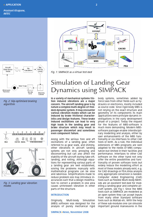
2SIMPACK »News, November 2008»Simulation of Landing Gear Dynamics using SIMPACK Fig. 1: SIMPACK as a virtual test-bed Fig. 2: Slip-optimised brakingalgorithmFig. 3: Landing gear vibrationmodes In a variety of mechanical systems fric-tion induced vibrations are a major concern. the aircraft landing gear is by nature a complex multi-degree-of-free-dom dynamic system. It may encounter various vibration modes which can be induced by brake frictional character-istics and design features. these brake induced oscillations can lead to very high loads in the landing gear and brake structure which may result in passenger discomfort and sometimes even component failure. Along with the serious fore and aft oscillations of a landing gear, often referred to as gear walk, and shimmy, other vibrations in aircraft landing systems are not only annoying and disconcerting but can also affect the stability of the aircraft during take-off, landing, and rolling. Although equa-tions for representing various parts of a landing gear are well established, solving the problems manually with mathematical programs can be slow and laborious. Simplifications made to reduce problem size may introduce in-accuracies such that a design modifica-tion to correct a problem in one area causes unforeseen vibration in other parts of the structure. INtroduCtIoN Originally, Multi-body Simulation (MBS) software was designed for the analysis of purely mechanical rigid body systems, sometimes added by force laws from other fields such as hy-draulics or electronics, mostly included as source code. Since rigid body MBS is not relying on the exact structure and geometry of its components its main applications were principle dynamic in-vestigations in the early development phase of a project. Today the request for the features of MBS-software is much more demanding. Modern MBS-software packages enable interdiscipli-nary modelling and analysis, either by user enhancements of the MBS func-tionality or via interfaces to other CAE tools or both. As a rule, the individual extensions of MBS programs are well adapted to the needs of MBS compu-tation but limited in their facilities and performance. Interfaces to other CAE software on the other hand not only offer the entire possibilities and func-tionality of proven software tools but widely reduce the modelling effort as most of these models already exist, e.g. for CAD drawings or FEA stress analysis only appropriate conversion is needed. Computer Aided Engineering (CAE) tools such as Flexible Multi-body Meth-ods are an excellent test-bed for mod-elling a landing gear and complete air-craft system, see Fig.1. Since the MBStools such as SIMPACK are modelled asan open system they can accept inputsfrom many other standard softwaretools such as Matlab etc. With the help of these sub-modules one can simulate important ground manoeuvres inthe3»Fig. 5: Effect of mechanical trailFig. 6: Shimmy Analysis Fig 4: Complex ground manouvre pre-design phase to save high costs offlight-tests.Clearly MBS is the favoured tool foranalysis of the dynamics of the landinggear and brake system. It also allowsconcurrent engineering with otherComputer Aided Engineering (CAE) tools such as Nastran which ensures ac-curate modelling for the purpose.ModellINg lANdINggeAr IN SIMPACKIn SIMPACK this multi-body system isrepresented by rigid body elementssuch as main-fitting, the shock tube,and two or four wheels, respectively.The shock absorbers (oleo) are locatedbetween the shock tube and main fit-ting. All landing gears have one trans-lational degree of freedom for theshock absorber and one rotational de-gree of freedom for each wheel.The main landing gears may have anadditional bogie attached to the shocktube with a rotational degree of free-dom along the y-axis with 4 wheels at-tached to it. To model landing gears oflarge aircraft such as A380 main land-ing gear which has 6 wheels, a bogie,and a pitch trimmer in addition can bemore complex. To model the systemsuccessfully one needs to define prop-er force elements to simulate the be-haviour of the system. SIMPACK has abuilt-in library of many force elementsand it is also possible to write so calleduser-routines which gives additionalfreedom to model different systems.Force elements apply external or inter-nal forces and torques in the system.They may depend upon the state of thesystem, e.g. the distance between twopoints, and upon time. Force elementsdo not affect the degrees of freedomof the system, but may introduce addi-tional states, or boundary conditions,to the differential equation system ofthe MBS model.The force elements describing thelanding gear characteristics havebeen modeled in detail for this workby means of so-called user-routines inSIMPACK. While the equations of thephysical phenomena as such are validindependently from the exact aircrafttype and can be taken from standardtextbooks the parameters for the forceelements are usually proprietary. It isalso possible to model individual bodyelements in a tool like NASTRAN andthen import it in SIMPACK using the interface FEMBS [3].For transport aircraft the main task of vertical energy dissipation is almost ex-clusively taken over by an oleo-pneu-matic shock-strut. This device combines a gas spring with oil and additional friction damping [1]. Damping force is provided by oil flow forced through an orifice by vertical strut motion. Often the oil flow is “controlled” by means of a metering pin. The gas spring is represented by a law of polytropic expansion as with spring force. The properties of the passive damper are determined by the laws describing the flow of a viscous fluid, e.g. oil, through an orifice. It is possible to program ac-tive, semi-active, and passive elements using either library elements or by means of user-elements in SIMPACK. Tyre elements can also be modelled the same way. One can make use of ‘Con-trol Elements’ in SIMPACK or SIMAT interface to model an ABS algorithm based on slip-optimization principle. It can be further enhanced as shown in Fig. 2. For further details about the force elements please refer to the lit-erature [1, 3].reSultS ANd ANAlySIS The results presented here are for a two mass model main landing gear of the Embraer regional aircraft and a complete large transport aircraft. It is possible to simulate complex ground manoeuvres using these sub-modules, see Fig. 5. With the help of modelling elements one can study landing gear and brake interaction and the related friction induced vibrations such as gear walk and shimmy, see Fig. 4. One can also perform parameter variation to study and optimize various parameters affecting landing gear shimmy. For the simulation of rolling and braking ma-noeuvres it is safe to assume that the aircraft is in static-equilibrium on the ground. This work was conducted by Dr. Khap-ane during his employment at DLR.literature 1. W .R. Krüger and M. Spieck, Interdisciplinary Landing Gear Layout for large Transport Air-craft. AIAA, 4964, 1998.2. R . Lernbeiss, Simulation eines Flugzeugfahr-werks bei elastischer Betrachtung des Feder-beines. Dipl.Arbeit at DLR, Oberpfaffenhofen.3. P . Khapane, Gear walk instability studies using flexible multibody methods in SIMPACK. Jour-nal of Aerosp.Sci.Technol., 10:19-25, 2006.。
收稿日期:2002-07-02 第19卷 第6期计 算 机 仿 真2002年11月 文章编号:1006-9348(2002)06-0087-02齿轮啮合力仿真计算的参数选取研究龙凯,程颖(北京理工大学车辆与交通工程学院,北京100081)摘要:该文通过建立某传动系统的三维实体模型,以Hertz 弹性撞击理论为基础,合理地定义了齿轮激振力的参数,利用多体动力学仿真软件ADA MS 进行了齿轮啮合力仿真计算,并给出某一特定传动条件下的齿轮激振力的计算结果。
结果表明,该文提出的齿轮激励力仿真计算时参数选取是合理的。
关键词:齿轮;激振力;仿真中图分类号:TP391.9 文献标识码:A1 前言如何准确、快速地确定齿轮传动激振力,对于正确分析齿轮系统动力学行为具有重要的意义[1]。
以Hertz 弹性撞击理论分析为基础,利用动力学仿真软件ADAMS 可以较方便地求取齿轮激振力,但计算参数选取对计算结果的准确性有很大影响,成为人们应用动力学仿真软件ADAMS 准确、快速解决实际问题的难点和重点。
本文对齿轮激振力仿真计算的参数确定进行了深入研究,合理地定义了仿真参数。
2 轮齿激振力的理论分析轮齿碰撞所引起的激励力,可以作为两个变曲率半径柱体撞击问题[2]。
解决此问题可以直接从Hertz 静力弹性接触理论中得到。
图1 两简单旋转体建立空间坐标系对于两简单旋转体建立空间坐标系如图1所示,用a 表示接触区的有效尺寸,用R 表示相对曲率半径,用R1和R2表示每个物体的有效半径,用l 表示物体横向和深度两方面的有效尺寸。
受到法向力P 作用。
变形前两表面上对应点S1(x ,y ,z1)和S2(x ,y ,z2)之间的间隙由Hertz 理论对接触区几何假设可得:h =x 2/2R +y 2/2R(1)其中1/R =1/R1+1/R2是相对曲率。
由于该表达式关于原点对称,接触区一定在原点两边扩展相同的距离。
在压缩过程中,两物体内远处的点T1和T2分别向着原点平行于z 轴移动位移δ1和δ2。
simpack齿轮修形参数
齿轮是机械传动中常见的一种装置,用于传递动力和转速。
在实际应用中,齿轮的修形参数是非常重要的,它们直接影响着齿轮的运行性能和寿命。
齿轮修形参数主要包括齿侧间隙、齿顶高度、齿根高度等。
齿侧间隙是齿轮齿廓与相邻齿轮齿廓之间的间隙,它的大小决定了齿轮的传动精度和运行平稳性。
齿顶高度是齿轮齿廓的最高点到基圆的距离,它的大小直接影响着齿轮的载荷能力和强度。
齿根高度是齿轮齿廓的最低点到基圆的距离,它的大小决定了齿轮的抗疲劳性能和寿命。
在simpack软件中,可以通过调整齿轮修形参数来优化齿轮的性能。
首先,我们需要根据实际需求和设计要求确定合适的修形参数范围。
然后,通过仿真分析和优化算法,找到最佳的修形参数组合。
在调整齿侧间隙时,我们可以根据齿轮的传动精度要求和承载能力来确定合适的间隙大小。
较小的间隙可以提高传动精度,但会增加齿轮的磨损和噪声;较大的间隙可以降低磨损和噪声,但会降低传动精度。
调整齿顶高度时,我们需要考虑到齿轮的载荷能力和强度要求。
较大的齿顶高度可以提高齿轮的载荷能力和强度,但会增加摩擦和磨损;较小的齿顶高度可以降低摩擦和磨损,但会降低载荷能力和强
度。
调整齿根高度时,我们需要考虑到齿轮的抗疲劳性能和寿命要求。
较大的齿根高度可以提高齿轮的抗疲劳性能和寿命,但会增加重量和成本;较小的齿根高度可以降低重量和成本,但会降低抗疲劳性能和寿命。
通过合理调整齿轮的修形参数,可以优化齿轮的性能和寿命。
在simpack软件中,我们可以通过模拟分析和优化算法,找到最佳的修形参数组合,从而实现齿轮的高效传动和可靠运行。
simpack齿轮啮合力
齿轮啮合力是指在齿轮传动中,两个啮合齿轮之间产生的力。
这个力的大小与齿轮的参数、工作条件以及传动系统的设计有关。
下面我将从多个角度来回答关于Simpack齿轮啮合力的问题。
首先,Simpack是一种用于多体动力学仿真的软件,可以模拟
机械系统的运动和力学行为。
在Simpack中,可以通过建立齿轮模
型来研究齿轮传动中的啮合力。
齿轮啮合力的计算通常涉及到齿轮的几何参数、材料特性、输
入转矩等因素。
Simpack可以通过定义齿轮的几何参数(如模数、
齿数、压力角等)和材料特性(如弹性模量、泊松比)来建立齿轮
模型。
然后,通过给定的输入转矩和工作条件(如转速、负载等),Simpack可以计算出齿轮啮合力。
此外,Simpack还可以考虑其他因素对齿轮啮合力的影响,比
如齿轮的偏心、振动和动态载荷等。
通过在Simpack中设置适当的
边界条件和加载条件,可以模拟实际工作条件下齿轮传动中的啮合力。
齿轮啮合力的大小对于齿轮传动的设计和分析非常重要。
通过Simpack的仿真分析,可以评估齿轮传动的工作性能、寿命和可靠性。
同时,还可以优化齿轮的设计参数,以满足特定的工作要求。
总结起来,Simpack可以用于建立齿轮模型并计算齿轮啮合力。
通过考虑齿轮的几何参数、材料特性和工作条件,Simpack可以提
供全面的齿轮啮合力分析和评估。
这对于齿轮传动的设计和优化具
有重要意义。