VF3330K-3GD1-02 SMC电磁阀
- 格式:doc
- 大小:735.64 KB
- 文档页数:3
DSG-03电磁换向阀的特点及应用2011年11月15日13:53时,7#高炉炉顶¢650液压放散阀自动打开,造成高炉减风,后续在更换电磁换向阀后再次造成放散阀打开,致使高炉二次减风。
后经原因分析,认为是电磁换向阀内部定位器失效,导致电磁阀误动作。
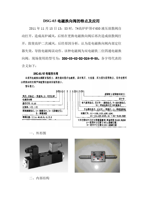
该种电磁阀为双电磁铁二位四通电磁换向阀,现场使用的型号为:DSG-03-02-D2-D24-N-50。
各字母代表的含义如下:一、外形图二、内部结构该阀主要由阀体1,一个或两个电磁铁,控制阀芯3和一个或两个复位弹簧4组成。
在未通电状态下,控制阀芯2由复位弹簧4保持在中位,或初始位置(脉冲阀芯除外)。
由湿式电磁铁2完成控制阀芯3的操作。
为确保正确的功能,务必在电磁铁衔铁压力腔中充满油液。
电磁铁2的力经推杆5作用在控制阀芯3上,将其由静止位置推到所需的切换位置。
使P至A和B至T,或有使P至B和A至T之间处于连通状态。
当电磁铁2断电时,控制阀芯3被复位弹簧4推回初始位置。
手动应急按钮6,用于在电磁铁不同电的情况下,驱动控制阀芯3的运动。
这是一种双电磁铁二位方向阀,带定位机构。
阀在两个位置之间切换。
在多数情况下,无需持续向电磁铁供电,阀可保持在任一切换位置。
其功能符号如下:三、炉顶放散阀液压原理及结构1、炉顶放散阀液压原理图如下所示:开炉顶液压系统液压泵共三台,采用两用一备的工作方式,目前启用为1#、2#液压泵。
P=20MPa N=37kW Q=95L/min n=1480r/min。
两台泵压力油共同进入系统主进油管,通往高炉40m平台阀站。
压力油由主进油管分别通过阀台到炉顶各阀油缸(共15个),通过阀台上的电磁换向阀实现压力油进出管路的切换实现各阀动作(其中包括炉顶放散)。
如图所示炉顶放散阀控制阀台主进油管路上有截止阀A、通过阀台后进回油管各有一截止阀B1、B2,阀台上依次有单向截止阀控制油路方向、溢流阀控制放散开关速度、二位四通电磁换向阀控制油路转换,均可通过远程计算机和机旁操作使电磁阀得、失电控制放散开关。

SMC比例阀工作原理[SMC ITV系列电气比例阀] 电气比例阀通过电信号控制气压力,可以实现气压力的连续、无级调节,能实现远程控制和程序控制,对于需要对气压力进行连续或者无级调节的场合,特别适用于电气比例阀。
对于SMC ITV系列电气比例阀有以下特点:1、灵敏度高、性能好。
保护等级为IP65.电缆方向有直线型和直角型。
2、SMC ITV0000系列为薄型(仅15mm),轻(100g)。
最多可集装至10位。
响应快(无负载时为0.1s)。
快换接头链接。
带错误显示灯(LED)。
3、SMC ITV2000/ITV3000系列为正压型,设定压力范围有三档。
在平衡状态时耗气量为0.在不加压状态下,可进行零位调整和满位调整。
在加压状态下若断电,能暂时保持输出压力不变。
有两种监控方式(模拟输出、开关输出)可供选择。
4、SMC ITV系列电气比例阀配线方法把电缆接到本体插座上应按SMC ITV系列电器使用说明书上的配线图进行配线。
配线一旦失误,阀可能损坏。
另外,DC电源应使用容量足够、电压波动小的电源。
5、SMC ITV系列电气比例阀特性曲线参见SMC ITV系列电气比例阀样本6、SMC ITV系列电气比例阀使用注意事项1)SMC ITV电气比例阀之前,应设置5μm以下过滤精度和油雾分离器,保证气源处理系统达到SMC压缩空气清净化系统第④系列的要求,向ITV比例阀提供清洁干燥的压缩空气,以便能达到ITV电气比例阀应有的各种特性。
2)SMC ITV电气比例阀之前,不得装油雾器。
3)SMC ITV电气比例阀在加压状态下切断电源,出口侧压力能暂时保持,但不能一直保持。
*SMC ITV电气比例阀其它使用注意事项,请参见SMC ITV系列电器使用说明书。
SMC ITV系列电气比例阀型号列表SMC ITV系列电气比例阀样本SMC ITV系列电气比例阀使用说明书SMC ITV电气比例阀配线图2、SMC ITV系列电气比例阀动作原理[SMC ITV系列电气比例阀动作原理图]SMC ITV2000/ITV3000系列电气比例阀动作原理图1-供气先导阀 2-膜片 3-排气阀 4-供气阀芯 5-先导室 6-压力传感器 7-排气先导阀8-控制回路[SMC ITV系列电气比例阀控制框图]SMC ITV2000/ITV3000系列电气比例阀控制框图SMC ITV2000/ITV3000系列电气比例阀动作原理图控制框图如上所示。

4V330C-10电磁阀的原理1. 电磁阀的基本原理电磁阀是一种利用电磁力控制流体流动的装置。
它由电磁铁和阀体组成,通过控制电磁铁的通断来控制阀门的开闭。
当电磁铁通电时,产生的磁场会吸引阀芯使之打开或关闭;当电磁铁断电时,磁场消失,弹簧的作用下使阀芯复位,从而控制流体的流动。
2. 4V330C-10电磁阀的特点4V330C-10电磁阀是一种常用的气动阀件,具有以下特点:- 通用性好,可与各种气动执行器组合使用;- 结构简单,零部件少,故障率低;- 可靠性高,使用寿命长;- 控制灵活,响应速度快。
3. 4V330C-10电磁阀的结构4V330C-10电磁阀一般由阀体、电磁线圈、阀芯、弹簧等部件组成。
其中,电磁线圈为电磁阀的核心部件,其通电后产生磁场,控制阀芯的移动;阀体内部布置有阀芯和弹簧,当电磁铁通电时,磁性铁芯吸引阀芯进行动作,从而控制气源的开关。
4. 4V330C-10电磁阀的工作原理4V330C-10电磁阀的工作原理是在电气信号的控制下,通过电磁阀内部的螺栓和阀芯的升降,实现通气和切断气路的转换。
具体步骤如下:(1) 施加电压:当给定电磁阀加上一定电压时,电磁线圈产生磁场,吸引阀芯往下移动;(2) 气路开通:阀芯移动到位后,气路打通,气源供气;(3) 断电弹簧复位:断电后,弹簧的作用下使阀芯复位关闭气路。
5. 4V330C-10电磁阀的应用领域4V330C-10电磁阀广泛应用于气动系统中,如气动控制设备、气动执行器等。
其控制灵活性和稳定性使其成为现代自动化控制系统中不可或缺的一部分。
由于其结构简单、使用寿命长等优点,也在工业自动化生产中得到了广泛的应用。
6. 4V330C-10电磁阀的维护与保养为确保4V330C-10电磁阀的正常运行,需要对其进行定期的维护与保养。
主要包括以下几个方面:- 定期清洗阀体和阀芯,保持其清洁;- 定期检查电磁线圈和连接线路,确保电路畅通;- 定期检查阀体和阀芯的密封性能,如有损坏及时更换。


方向控制器4、5通先导式电磁阀1》4通电磁阀/盒式集装式SJ:1.SJ2000系列/CAD,2.SJ3000系列/CAD卖点特长:扁平盒式结构。
省空间:阀宽7.5mm(SJ2000)、10mm(SJ3000)。
SJ2000、SJ3000可混装使用。
采用插座式连接方式,易于增减集装位数和阀的更换。
单电控。
具有4位双3通阀规格。
2》真空节流破坏阀SJ3A6系列卖点特长:内置有2个滑阀。
能够用1个阀来控制真空吸着和破坏。
阀宽10mm(与SJ3000系列相同)。
带有能够调节空气流量的节流阀。
真空侧与破坏侧内置多种可交换的过滤器。
可以与4通电磁阀SJ2000/SJ3000混合使用。
3》5通电磁阀SY:1.SY3000系列2.SY5000系列3. SY7000系列4.SY9000 系列卖点特长:3通阀和5通阀能够混合安装使用。
消耗功率:0.1W (带省电回路)有铝制一体型、DIN导轨式、组合集装型等丰富的集装式类型可供选择。
4》新款5通电磁阀新SY:1.SY3000系列2.SY5000系列卖点特长:阀体宽度不变,流量最多增加80%SY3000宽:10mm、SY5000宽:15mm。
寿命2亿次(金属密封)7000(橡胶密封)插入式金属底板(IP40)/插入式插件连接底板(IP67)底面配管,省空间5》5通电磁阀SV:1.SV10002系列2.SV2000系列3.SV3000系列4.SV4000系列卖点特长:便于实现集装式阀的增连以及规格变更。
单电控。
具有4位双3通阀规格。
6》4、5通电磁阀SYJ1.SYJ3000系列2.SYJ5000系列3.SYJ7000系列卖点特长:3通阀和5通阀能够混合安装使用。
消耗功率:0.1W (带省电回路)7》5通电磁阀/盒式集装式SZSZ3000系列卖点特长:具有便于实现阀的交换的盒式结构。
带有开关的阀使得维护时更安全。
采用扁平盒式结构更加节省空间。
8》大型5通电磁阀VP1.VP4□50系列2.VP4□70系列卖点特长:用于大型缸驱动。
Piping for the One-touch fitting•Insert the tube all the way into the fittingso that it cannot be pulled out.•Insertion with excessive force can cause damage.•Ensure there is no leakage after piping.•Use the product within the specified operating pressure and temperature range.TroubleshootingSpecifications / DimensionsRefer to the product catalogue or operation manual from SMC website(URL ) for more information about the product specifications anddimensions.Note: Specifications are subject to change without prior notice and any obligation on the part of the manufacturer.© 2011-2015 SMC Corporation All Rights ReservedAkihabara UDX 15F, 4-14-1, Sotokanda, Chiyoda-ku, Tokyo 101-0021, JAPANPhone: +81 3-5207-8249 Fax: +81 3-5298-5362URL Refer to the operation manual from SMC website (URL ) for moreinformation about troubleshooting.Function SettingPress the S buttonfor 2 secondsor longer.Press the S button once in measurement mode.[P_1] or [n_1] and [the current set value] are displayed in turn.in turnS∗: For models with switch outputs for both OUT1 and OUT2, [P_2] or [n_2] will be displayed too.Set as above.∗: If a mode other than Hysteresis Mode is selected, refer to the operation manual from SMC website(URL ) or contact SMC.∗: Note that the set value and hysteresis settings are limited by each other.<Operation>(The illustration shows PFMB7201, when not using the reversed display function.)Press the △or ▽button to change the set value.The △button is to increase and the ▽button is to decrease the set value.Press the△button continuouslyto keep increasing the set value.Press the S button to complete the setting.Return to measurement mode.S∗2: This setting is only available for models with switch outputs for both OUT1 and OUT2.∗3: This setting is only available for models with the external input.∗4: This setting is only available for models with the analogue output.Peak/Bottom value displayThe maximum (minimum) flow from when the power was supplied to this moment isdetected and updated. In peak/bottom display mode, the maximum (minimum) flow isdisplayed•For peak display, when the △button is pressed for 1 second or longer,[the maximum flow] and [Hi] are displayed in turn.To release holding the display of the maximum flow, press the △button for 1 second orlonger again to return to measurement mode.•For bottom display, when the ▽button is pressed for 1 second or longer,[the minimum flow] and [Lo] are displayed in turn.To release holding the display of the minimum flow, press the ▽button for 1 second orlonger again to return to measurement mode.If the △and ▽buttons are pressed simultaneously for 1 second or longer while the flowvalue is being held, the peak (bottom) values are reset.Reset operationThe accumulated flow value can be reset, when displaying the accumlated flow.The reset the accumulated flow, press the △and ▽buttons simultaneously for1 second or longer.The peak/bottom value can be reset, when displaying the peak value (bottom value).To reset the peak/bottom value, press the △and ▽buttons simultaneously for 1 secondor longer.Key lock functionTo use each of these functions, refer to the operation manual from SMC website(URL ) or contact SMC.MaintenanceTo change setting, refer to the operation manual from SMC website(URL ) or contact SMC.12321Safety InstructionsMounting•Never mount the product in a place where it will be used as a mechanical support.•Mount the product so that the fluid flows in the direction indicated by the arrow on the sideof the body.Safety InstructionsMounting and InstallationThese safety instructions are intended to prevent hazardous situations and/orequipment damage.These instructions indicate the level of potential hazard with the labels of"Caution", "Warning" or "Danger". They are all important notes for safety and mustbe followed in addition to International standards (ISO/IEC) and other safetyregulations.InstallationPanel mounting (Only PFMB7201)•Refer to the diagram and table below for mounting details.•Refer to the dimension from SMC website (URL )for panelthickness and panel mount cut-out dimensions.OperatorBodyPFMB7201PFMB7501/7102/7202DisplayPFMB7201PFMB7501/7102/7202Bracket mounting•Refer to the diagram and table below for mounting details.•Refer to the dimension from SMC website (URL )for bracketthickness and mounting hole dimensions.Connecting/Disconnecting•When mounting the connector, insert it straight into the socket, holding the lever andconnector body, and push the connector until the lever hooks into the housing, and locks.+ 2 1-1234Power is supplied∗: The outputs will continue to operate during setting.∗: If a button operation is not performed for 30 seconds during the setting, the display will flash.(This is to prevent the setting from remaining incomplete if, for instance, an operator were to leave during setting)∗: 3 step setting mode and Function selection mode are reflected on each other.Flow Setting (set value only) of OUT1 · OUT2Flow[L/min][H_1]Switch ONSwitch OFFSet value[P_1]Outline of settingsDIN rail mounting (Only PFMB7201)•Refer to the diagram and table below formounting details.3 step setting modeIn this mode, only the set values can be input, in just 3 steps.∗: When the reversed display is used, the function of the△and▽buttons is reversed.Piping•Never mount the product upside down.•The straight piping length shall be 8 cm or longer.Otherwise, if a straight section of piping is not installed, the accuracy varies byapproximately ±2%F.S.•Avoid sudden changes in the piping size on the IN side of the product.•Do not release the OUT side piping port of the product directly to the atmospherewithout the piping connected.If the product is used with the piping port released to atmosphere, the accuracy may vary.Piping for the metal attachment•Tighten to the specified torque. Refer to the table below for the required torque values.•Use a suitable spanner for the appropriate torque. Do not use a spanner 40 cm orlonger.•If the tightening torque is exceeded, the product can be broken.If the tightening torque is insufficient, the fitting may become loose.•Avoid any sealing tape getting inside the flow path.•Ensure there is no leakage after piping.•When mounting the fitting, a spanner should be used on the metal part (attachment) ofthe fitting only.Holding other parts of the product with a spanner may damage the product.Specifically, make sure that the spanner does not damage the connector.Direct mounting•Refer to the diagram and table below for mounting details.•Refer to the dimension from SMC website (URL )for mountinghole size.Thank you for purchasing an SMC PFMB7 series Digital Flow Switch.Please read this manual carefully before operating the product and make sure youunderstand its capabilities and limitations. Please keep this manual handy forfuture reference.Before UseDigital Flow SwitchPFMB7201/7501/7102/7202Connector pin numbers (lead wire)Press the▽button continuouslyto keep decreasing the set value.PF※※-OMP0003-AHow to reset the product after a power cut or when the power has beenunexpectedly removedThe settings of the product are retained from before the power cut orde-energizing.The output condition also recovers to that before power cut or de-energizing, butmay change depending on the operating environment. Therefore, check the safetyof the whole installation before operating the product.settingsdefault settings are shown below.When the flow exceeds the set value [P_1], the switch will be turned ON.When the flow falls below the set value by the amount of hysteresis [H_1] or more, theswitch will turn OFF.If the operation shown in the diagram below is acceptable, then keep these settings.For more detailed settings, set each function in the function selection mode.Default settingsWiringConnection•Connections should only be made with the power supply turned off.•Use a separate route for the product wiring and any power or high voltage wiring.Otherwise, malfunction may result due to noise.•Ensure that the FG terminal is connected to ground when using a commerciallyavailable switch-mode power supply. When a switch-mode power supply is connectedto the product, switching noise will be superimposed and the product specification canno longer be met. This can be prevented by inserting a noise filter, such as a line noisefilter and ferrite core, between the switch-mode power supply and the product or byusing a series power supply instead of a switch-mode power supply.Error indicationNOTEThe direct current power supply used should be UL approved as follows.Circuit (class 2) of maximum 30 Vrms (42.4 V peak) or less, with UL 1310class 2 power supply unit or UL 1585 class 2 transformer.The product is a UL approved product only if it has a mark on the body.Function selection modeIn measurement mode, press the S button for 2 seconds or longer, to display [F 0].The [F] indicates the mode for changing each Function Setting.Press the S button for 2 seconds or longer in function selection mode to return tomeasurement mode.。
Doc. no. VP3145-OMH0005-D3 Port Air Operated ValveSeries: VPA31∗5Safety Instructions ---------------------------------------------------------------------------------- 2,3 Design -------------------------------------------------------------------------------------------------- 4 Selection ----------------------------------------------------------------------------------------------- 4 Mounting ----------------------------------------------------------------------------------------------- 4 Piping --------------------------------------------------------------------------------------------------- 5 Lubrication --------------------------------------------------------------------------------------------- 5 Air Supply --------------------------------------------------------------------------------------------- 5 Operating Environment----------------------------------------------------------------------------- 5 Maintenance ------------------------------------------------------------------------------------------- 5 Specific Product Precautions ---------------------------------------------------------------------- 6,7 Trouble shooting -------------------------------------------------------------------------------------- 8 Remedy ------------------------------------------------------------------------------------------------- 9Safety InstructionsThese safety instructions are intended to prevent hazardous situations and/or equipment damage.These instructions indicate the level of potential hazard with the labels of “Caution,” “Warning” or “Danger.” They are all important notes for safety and must be followed in addition to International Standards (ISO/IEC)*1) , and other safety regulations.*1) ISO 4414: Pneumatic fluid power -- General rules relating to systems. ISO 4413: Hydraulic fluid power -- General rules relating to systems.IEC 60204-1: Safety of machinery -- Electrical equipment of machines .(Part 1: General requirements)ISO 10218: Manipulating industrial robots -Safety. etc.Caution Caution indicates a hazard with a low level of risk which, if not avoided, could resultin minor or moderate injury.Warning Warning indicates a hazard with a medium level of risk which, if not avoided, could result in death or serious injury.DangerDanger indicates a hazard with a high level of risk which, if not avoided, will resultin death or serious injury.Warning 1. The compatibility of the product is the responsibility of the person who designs the equipment ordecides its specifications.Since the product specified here is used under various operating conditions, its compatibility with specific equipment must be decided by the person who designs the equipment or decides its specifications based on necessary analysis and test results.The expected performance and safety assurance of the equipment will be the responsibility of the person who has determined its compatibility with the product.This person should also continuously review all specifications of the product referring to its latest catalog information, with a view to giving due consideration to any possibility of equipment failure when configuring the equipment.2. Only personnel with appropriate training should operate machinery and equipment.The product specified here may become unsafe if handled incorrectly.The assembly, operation and maintenance of machines or equipment including our products must be performed by an operator who is appropriately trained and experienced.3. Do not service or attempt to remove product and machinery/equipment until safety is confirmed.1.The inspection and maintenance of machinery/equipment should only be performed after measures to prevent falling or runaway of the driven objects have been confirmed.2.When the product is to be removed, confirm that the safety measures as mentioned above are implemented and the power from any appropriate source is cut, and read and understand the specific product precautions of all relevant products carefully.3. Before machinery/equipment is restarted, take measures to prevent unexpected operation and malfunction.4. Contact SMC beforehand and take special consideration of safety measures if the product is to be used in any of the following conditions.1. Conditions and environments outside of the given specifications, or use outdoors or in a place exposed to direct sunlight.2. Installation on equipment in conjunction with atomic energy, railways, air navigation, space, shipping, vehicles, military, medical treatment, combustion and recreation, or equipment in contact with food and beverages, emergency stop circuits, clutch and brake circuits in press applications, safety equipment or other applications unsuitable for the standard specifications described in the product catalog.3. An application which could have negative effects on people, property, or animals requiring special safety analysis.e in an interlock circuit, which requires the provision of double interlock for possible failure by using a mechanical protective function, and periodical checks to confirm proper operation.Safety InstructionsCaution1. The product is provided for use in manufacturing industries.The product herein described is basically provided for peaceful use in manufacturing industries.If considering using the product in other industries, consult SMC beforehand and exchange specifications or a contract if necessary.If anything is unclear, contact your nearest sales branch.Limited warranty and Disclaimer/Compliance RequirementsThe product used is subject to the following “Limited warranty and Disclaimer” and “Compliance Requirements”.Read and accept them before using the product.Limited warranty and Disclaimer1.The warranty period of the product is 1 year in service or 1.5 years after the product is delivered,whichever is first.∗2)Also, the product may have specified durability, running distance or replacement parts. Please consult your nearest sales branch.2. For any failure or damage reported within the warranty period which is clearly our responsibility,a replacement product or necessary parts will be provided.This limited warranty applies only to our product independently, and not to any other damage incurred due to the failure of the product.3. Prior to using SMC products, please read and understand the warranty terms and disclaimers noted in the specified catalog for the particular products.∗2) Vacuum pads are excluded from this 1 year warranty.A vacuum pad is a consumable part, so it is warranted for a year after it is delivered.Also, even within the warranty period, the wear of a product due to the use of the vacuumpad or failure due to the deterioration of rubber material are not covered by the limitedwarranty.Compliance Requirements1. The use of SMC products with production equipment for the manufacture of weapons of massdestruction(WMD) or any other weapon is strictly prohibited.2. The exports of SMC products or technology from one country to another are governed by therelevant security laws and regulation of the countries involved in the transaction. Prior to the shipment of a SMC product to another country, assure that all local rules governing that export are known and f ollowed.CautionSMC products are not intended for use as instruments for legal metrology.Measurement instruments that SMC manufactures or sells have not been qualified by type approval tests relevant to the metrology (measurement) laws of each country.Therefore, SMC products cannot be used for business or certification ordained by the metrology (measurement) laws of each country.WarningWarningDesign / Selection1. Confirm the specifications. Products represented in this manual are designed only for use in compressed air systems (including vacuum).Do not operate at pressures or temperatures, etc., beyond the range of specifications, as this can cause damage or malfunction. (Refer to the specifications.)Please contact SMC when using a fluid other than compressed air (including vacuum).We do not guarantee against any damage if the product is used outside of the specification range.2. Actuator driveWhen an actuator, such as a cylinder, is to be driven using a valve, take appropriate measures (cover installation or approach prohibition) to prevent potential danger caused by actuator operation.3. Holding pressure (including vacuum)Since the valves are subject to air leakage, they cannot be used for applications such as holding pressure (including vacuum) in a pressure vessel.4. Not suitable for use as an emergency shutoff valve, etc.The valves listed in this manual are not designed for safety applications such as an emergency shutoff valve. If the valves are used for the mentioned applications, additional safety measures should be adopted.5. Release of residual pressureFor maintenance purposes install a system for releasing residual pressure.6. Operation in a vacuum conditionWhen a valve is used for switching a vacuum, take measures to install a suction filter or similar to prevent external dust or other foreign matter from entering inside the valve. In addition, at the time of vacuum adsorption, be sure to vacuum at all times. Failure to do so may result in foreign matter sticking to the adsorption pad, or air leakage causing the workpiece to drop.7. Regarding a vacuum switch valve and a vacuum release valveIf a non-vacuum valve is installed in the middle of piping system having a vacuum, the vacuum condition will not be maintained. Use a valve designed for use under vacuum condition.8. VentilationProvide ventilation when using a valve in a confined area, such as in a closed control panel. For example, install a ventilation opening, etc. in order to prevent pressure from increasing inside of the confined area.9 .Do not disassemble the product or make any modifications, including additional machining.Doing so may cause human injury and/or an accident. When the product is disassembled for maintenance, refer to “Overhaul / Cleaning / Addition of grease (VPA31*5V series: Vacuum Specification)”.Selection1. Use in low temperature environments Valve use is possible to temperature to 0o C. Take appropriate measures to avoid freezing or congealing of drain, water, etc.2. Pilot airThe pilot port should be pressurized by a compressed air at the specified pressure.3. Mounting orientationMounting orientation is free.Mounting1. Operation manualInstall the products and operate them only after reading the operation manual carefully and understanding its contents. Also, keep the manual where it can be referred to as necessary.2. Ensure sufficient space for maintenance activities.When installing the products, allow access for maintenance.3. Tighten threads with the proper tightening torque.When installing the products, follow the listed torque specifications.4. If air leakage increases or equipment does not operate properly, stop operation.Check mounting conditions when air and power supplies are connected. Initial function and leakage tests should be performed after installation.5. Painting and coatingWarnings or specifications printed or affixed to the product should not be erased, removed or covered up.Please consult with SMC before applying paint to resinous parts, as this may have an adverse effect due to the solvent in the paint.Be sure to read before handling.CautionWarningWarningPiping1. Preparation before pipingBefore piping is connected, it should be thoroughly blown outwith air (flushing) or washed to remove chips, cutting oil andother debris from inside the pipe.2. Wrapping of pipe tapeWhen screwing piping orfittings into ports, ensure thatchips from the pipe threads orsealing material do not enterthe piping. Also, if pipe tape isused, leave 1 thread ridgesexposed at the end of thethreads.3. Connection of fittingsWhen screwing fittings into valves, tighten as follows.Tightening Torque for PipingConnection thread size (R, NPT)Proper tightening torque (N·m)1/8 3~53/8 15~201/2 20~253/4 28~301 36~381 1/440~421 1/248~502 48~50Follow the procedure of the manufacturer when fittings other thanSMC is used.1) If the fitting is tightened with excessive torque, a large amountof sealant will seep out. Remove the excess sealant.2) Insufficient tightening may cause seal failure or loosen thethreads.3) For reuse(1) Normally, fittings with a sealant can be reused up to 2 to 3times.(2) To prevent air leakage through the sealant, remove anyloose sealant stuck to the fitting by blowing air over thethreaded portion.(3) If the sealant no longer provides effective sealing, windsealing tape over the sealant before reusing. Do not use anyform of sealant other than the tape type of sealant.(4) Once the fitting has been tightened, backing it out to itsoriginal position often causes the sealant to becomedefective. Air leakage will occur.4. Uni thread fittings1) First, tighten the threaded portion by hand, then use a suitablewrench to tighten the hexagonal portion of the body further atwrench tightening angle shown below. For the reference valuefor the tightening torque, refer to the table below.Connection Female Thread: Rc, NPT, NPTFUni thread sizeWrench tightening angleafter tightened by hand(deg)Tightening torque(N·m)1/8 30 to 60 3 to 53/8 15 to 45 14 to 161/2 15 to 30 20 to 22Connection Female Thread: GUni thread sizeWrench tightening angleafter tightened by hand(deg)Tightening torque(N·m)1/8 30 to 45 3 to 43/8 15 to 30 8 to 91/2 15 to 3014 to 152) The gasket can be reused up to 6 to 10 times. It can bereplaced easily when it has sustained damage. A broken gasketcan be removed by holding it and then turning it in the samedirection as loosening the thread. If the gasket is difficult toremove, cut it with nippers, etc. In such a case, use caution notto scratch the seat face because the seat face of the fitting’s45° gasket is the sealing face.5. Piping to productsWhen piping to a product, refer to the operation manual toavoid mistakes regarding the supply port, etc.LubricationThis is a valve which requires lubrication. Besure to lubricate it for operation.It may cause problems such as damage andmalfunction of the valve if it is not lubricated.A valve of vacuum specification needs overhaulfor cleaning and addition of grease because itcannot be lubricated without it. (Refer to page 8.)1) If a lubricant is used in the system, use class 1 turbine oil (noadditive), ISO VG32.2) Please contact SMC regarding class 2 turbine oil (withadditives), ISO VG32.Lubrication amountIf too much oil is supplied, the oil will be accumulated in theproduct, causing malfunction or response delay.Air Supply1. Use clean air.Do not use compressed air that contains chemicals, syntheticoils including organic solvents, salt or corrosive gases, etc., asit can cause damage or malfunction.1. Install an air filter.Install an air filter upstream near the valve. Select an air filterwith a filtration size of 5 ㎛or smaller.2. Take measures to ensure air quality, such as byinstalling an aftercooler, air dryer, or waterseparator.Compressed air that contains a large amount of drainage cancause malfunction of pneumatic equipment such as valves.Therefore, take appropriate measures to ensure air quality,such as by providing an aftercooler, air dryer, or waterseparator.Be sure to read before handling.CautionCautionWarningWarningAir Supply3. If excessive carbon powder is seen, install a mist separator on the upstream side of the valve.If excessive carbon dust is generated by the compressor, it may adhere to the inside of a valve and cause it to malfunction.For compressed air quality, refer to SMC’s Best Pneumatics catalog.Operating Environment1. Do not use in an atmosphere having corrosivegases, chemicals, sea water, water, water steam, or where there is direct contact with any of these . 2. Do not use in an environment where flammable gas or explosive gas exists. Usage may cause a fire or explosion.The products do not have an explosion proof construction.3. Do not use in a place subject to heavy vibration and/or shock.4. The valve should not be exposed to prolonged sunlight. Use a protective cover.Note that the valve is not for outdoor use. 5. Remove any sources of excessive heat.6. If it is used in an environment where there is possible contact with a waterdrop, oil, weld spatter, etc., exercise preventive measures.(1) Temperature of ambient environmentUse the valve within the range of the ambient temperature specification of each valve. In addition, pay attention when using the valve in environments where the temperature changes drastically.(2) Humidity of ambient environmentIf the humidity rises, take measures to prevent the adhesion of water droplets on the valve.Maintenance1. Perform maintenance inspection according to the procedures indicated in the operation manual.If handled improperly, malfunction and damage of machinery or equipment may occur.2. Removal of equipment, and supply/exhaust of compressed airWhen components are removed, first confirm that measures are in place to prevent workpieces from dropping, run-away equipment, etc. Then, cut off the supply pressure and electric power, and exhaust all compressed air from the system using the residual pressure release function.When the equipment is operated after remounting or replacement, first confirm that measures are in place to prevent lurching of actuators, etc. Then, confirm that the equipment is operating normally.3. Low frequency operationValves should be operated at least once every 30 days to prevent malfunction. (Use caution regarding the air supply.)4. If the volume of air leakage increases or the valve does not operate normally, do not use the valve.Perform periodic maintenance on the valve to confirm the operating condition and check for any air leakage.1. Drain flushing Remove drainage from the air filters regularly.CautionCautionCautionVPA31∗5 SeriesPrecautions for 3 Port Air Operated Valve ③Be sure to read before handling.Other Precautions1. Pressure balance among each portThis valve is pressure-unbalanced type. Operate it within this pressure range: IN ≧ OUT ≧ EXH. If not operated in the range, the valve will malfunction.2. Use as 2 port valve1) Plug EXH port in case of pressure-in and plug IN port in case of vacuum use.2) This valve has slight air leakage and can not be used for such purposes as holding air pressure (including vacuum) in the pressure container.3. Piping (Vacuum Use)1) Piping in general:Vacuum pump/BlowerVacuum pad/TankPlug (2 port valve)IN port = Air releasingAir pressure-inEXH port = (Suction side)OUT port = (Load side)VPA31∗5 SeriesSpecific Product PrecautionsBe sure to read before handling .Caution1) How to overhaul (Remove air supply before starting disassembly .)Remove the four hexagon socket head cap screws ○11and take the housing. The guide ring ○9 can be found on the body, and take it away with a flat head screw driver to take the internal parts away.2) How to add greaseTake the parts off and wipe off the dust adhered on them.Wipe off the dust inside the body ○1, too. Take the O-rings ○5 and ○7 in the sliding part off of the spool valve ○6, wipe them to clean and apply grease. Apply grease to the portion A of the spool valve ○6, internal surface of the guide ring and portions B, C, D of the body ○1, too. Note 1) Do not wash the O-ring and the spool valve with organic solvent or such.Note 2) It is suggested to use the silicone grease “G-40M” made by Shin-Etsu Chemical Co., Ltd.3) Overhaul1. Insert the element ○2 and the spring washer ○3 in the direction that the figure shows. 2. Insert the spool valve ○6 and the guide ring ○9 together into the body ○1.*Be sure to have a performance inspection and an air leakage test after overhaul of the valve.Performance deterioration, damage and such caused by overhaul for cleaning are out of SMC’s guarantee. (Contact SMC for repair if it needs to be guaranteed.)∗VPA31∗5 SeriesSpecific Product Precautions ②Be sure to read before handling .- 8 -VP3145-OMH0005-DTrouble shootingRemedy)①⑤According to the failure, check the cause of the failure from which seems to effect the failure more than the other and devise a countermeasure.⑥④②③- 9 -VP3145-OMH0005-DRemedyIf no improvement is achieved in spite of the above countermeasure, inside of the valve may have somefailure. In this case, stop using the valve immediately.If any of followings are carried out, inside of the valve may have some failure. In this case, stop usingthe valve immediately.1. Oil other than the specified one has been lubricated.2. Lubrication has been stopped intermediately, or lubrication was suspended temporary.3. Water splashed directely.4. Strong impact was given.5. Foreign matter such as drain and particle invaded.6. Prohibited way of using the valve which is written at ''Precautions'' section in this operationmanual was carried out excluding above-mentioned.∗ Return us the failure valve in just the state when the failure occurred to the valve.- 10 -VP3145-OMH0005-D□D R enewal2018.8 4-14-1, Sotokanda, Chiyoda-ku, Tokyo 101-0021 JAPANTel: + 81 3 5207 8249 Fax: +81 3 5298 5362URL Note: Specifications are subject to change without prior notice and any obligation on the part of the manufacturer.© 2018 SMC Corporation All Rights ReservedVP3145−OMH0005−D。
主管道过滤器 AFF11C-06D-T AFF11C-06D-T 油雾分离器AM450C-06D-T AM450C-06D-T 冷冻式干燥机IDFA11E-23IDFA11E-23自动排水器AD400-04AD400-04自动排水器AD402-04AD402-04三联件AC20-02-A AC20-02-A三联件AC20-02C-A AC20-02C-A三联件AC30-03-A AC30-03-A三联件AC30-03D-A AC30-03D-A三联件AC40-04-A AC40-04-A三联件AC40-04D-A AC40-04D-A两联件AC20A-02-A AC20A-02-A两联件AC20A-02C-A AC20A-02C-A两联件AC30A-03-A AC30A-03-A两联件AC30A-03D-A AC30A-03D-A两联件AC40A-04-A AC40-04-A两联件AC40A-04D-A AC40-04D-A过滤减压阀AW20-02-A AW20-02-A过滤减压阀AW20-02C-A AW20-02C-A过滤减压阀AW30-03-A AW30-03-A过滤减压阀AW30-03D-A AW30-03D-A过滤减压阀AW40-04-A AW40-04-A过滤减压阀AW40-04D-A AW40-04D-A空气过滤器AF30-03D-A AF30-03D-A减压阀AR20-02-A AR20-02-A减压阀AR30-03-A AR30-03-A减压阀AR40-04-A AR40-04-A油雾器AL30-03-A AL30-03-A压力表G36-10-01G36-10-01压力表G46-10-01G46-10-01安装托架AR22P-270AS AR22P-270AS安装托架AR32P-270AS AR32P-270AS安装托架AR42P-270AS AR42P-270AS油雾分离器AFM40-04D-A AFM40-04D-A微雾分离器AFD40-04D-A AFD40-04D-A电磁阀SY5120-4LZD-01SY5120-4LZD-01电磁阀SY5120-4DZD-01SY5120-4DZD-01电磁阀SY5120-5LZD-01SY5120-5LZD-01电磁阀SY5120-5DZD-01SY5120-5DZD-01电磁阀SY5220-5DZD-01SY5220-5DZD-01电磁阀SY5320-5DZD-01SY5320-5DZD-01电磁阀SY7120-4LZD-02SY7120-4LZD-01电磁阀SY7120-4DZD-02SY7120-4DZD-01电磁阀SY7120-5LZD-02SY7120-5LZD-01电磁阀SY7120-5DZD-02SY7120-5DZD-01电磁阀SY7220-5DZD-02SY7220-5DZD-01电磁阀SY7320-5DZD-02SY7320-5DZD-01电磁阀SY9120-5DZD-03SY9120-5DZD-01电磁阀VFS1120-5DZB-01VFS1110-5DZD-01电磁阀VF3130-5DZB-02VFS2120-5DZD-02电磁阀VF5120-5DZB-03VF3130-5DZD-01电磁阀VFS4110-5DZB-04VF5110-5DZD-01消音器AN101-01AN101-01消音器AN10-01A10-01消音器AN20-02/AN30-03/AN40-04AN20-02/30-03/40-04排气节流阀ASN2-01/02/03/04ASN2-01/02/-03/-04单向节流阀AS1201F-M5-06A AS1101-M5-06A单向节流阀AS2201F-01-06SA AS1101-01-06AS单向节流阀AS2201F-02-06S AS2101-02-06A单向节流阀AS3201F-03-08S AS3101-03-08A单向节流阀AS4201F-04-10S AS4101-04-10A气管TU0604BU-20TU0604BU-20气管TU0805BU-20TU0805BU-20气管TU1065BU-20TU1065BU-20气管TU1208BU-20TU1208BU-20接头KQ2H06-01AS KQ2H06-01-A接头KQ2L08-02AS KQ2L08-02-A接头KQ2T04-00A KQ2T04-00-A接头KQ2U10-00A KQ2U10-00-A接头KQ2H12-00A KQ2H12-00-A变径接头KQ2R06-08A KQ2R06-08-A隔板接头KQ2E04-00A KQ2E04-00-A隔板接头KQ2E12-03A KQ2E12-03-APLU1/4PLU1/4口径3/4,自动排水,带滤芯闭塞指示器口径3/4,自动,带滤芯闭塞指示器适用11KW,环保冷媒,不锈钢热交换器,已带自动排水器,接管口径3/4口径1/2,自动排水,带手动开关口径1/2,自动排水口径1/4,手动排水,带托架Y200T两件,不带压力表口径1/4,自动排水,带托架Y200T两件,不带压力表口径3/8,手动排水,带托架Y300T两件,不带压力表口径3/8,自动排水,带托架Y300T两件,不带压力表口径1/2,手动排水,带托架Y400T两件,不带压力表口径1/2,自动排水,带托架Y400T两件,不带压力表口径1/4,手动排水,带托架Y200T一件,不带压力表口径1/4,自动排水,带托架Y200T一件,不带表口径3/8,手动排水,带托架Y300T一件,不带表口径3/8,自动排水,带托架Y300T一件,不代表口径1/2,手动排水,带托架Y400T一件,不带表口径1/2,自动排水,带托架Y400T一件,不带表口径1/4,手动排水,不带托架不带表口径1/4,自动排水,不带托架不带表口径3/8,手动排水,不带托架不带表口径3/8,自动排水,不带托架不带表口径1/2,手动排水,不带托架不带表口径1/2,自动排水,不带托架不带表口径3/8,自动排水,不带托架口径1/4,不带托架不带表口径3/8,不带托架不带表口径1/2,不带托架不带表口径3/8,不带托架口径1/8,适用AC/AW/AR---20,30系列口径1/8,适用AC/AW/AR---40系列适用AW/AR---20系列适用AW/AR---30系列适用AW/AR---40系列口径1/2,自动排水,不带托架口径1/2,自动排水,不带托架口径1/8,2位5通单电控AC220V,不带托架口径1/8,2位5通单电控AC220V,不带托架口径1/8,2位5通单电控DC24V,不带托架口径1/8,2位5通单电控DC24V,不带托架口径1/8,2位5通双电控DC24V,不带托架口径1/8,3位5通电磁阀DC24V,不带托架口径1/4,2位5通单电控AC220V,不带托架口径1/4,2位5通单电控AC220V,不带托架口径1/4,2位5通单电控DC24V,不带托架口径1/4,2位5通单电控DC24V,不带托架口径1/4,2位5通双电控DC24V,不带托架口径1/4,3位5通电磁阀DC24V,不带托架口径3/8,2位5通单电控DC24V口径1/8,2位5通单电控DC24V口径1/4,2位5通单电控DC24V口径3/8,2位5通单电控DC24V口径1/2,2位5通单电控DC24V口径1/8,烧结金属型口径1/8,树脂型口径对应1/4,3/8/,1/2,树脂型口径1/8,1/4,3/8,1/2口径M5,插管6口径1/8,插管6口径1/4,插管6口径3/8,插管8口径1/2,插管10PU气管,外径6,内径4,颜色蓝色,20米1卷PU气管,外径8,内径5,颜色蓝色,20米1卷PU气管,外径10,内径6.5,颜色蓝色,20米1卷PU气管,外径12,内径8,颜色蓝色,20米1卷插管6,螺纹1/8,直通型插管8,螺纹1/4,直角型T型三通插管4Y型三通插管10直通双边插管128接头变径6快插隔板两边插管4隔板一边插管12,一边内螺纹3/8堵头1/4。