意科IECCO 安装调试指南(690V)
- 格式:pdf
- 大小:1.71 MB
- 文档页数:40

安全声明为保证安全、正确、高效地使用装置,请务必阅读以下重要信息。
警告!a)严格遵照执行国家及电力行业相关安全规程。
工作在高电压环境下,应严肃认真对待,以避免人身伤害或设备损坏;b)在操作中不应触摸电路,可能会有致命的电压、电流;c)在拆卸开装置面板后,应避免触及电路,产品包含电子电路,如果遭受静电,可能会受到损坏。
电子电路也可能含有致命的高电压;d)不管运行条件如何,必须将装置与保护地相连。
这也适用于一些特殊的场合,如在台桌上测试演示及离线配置。
不经恰当接地操作装置,可能会损坏装置,也可能会发生事故引起伤害;e)在正常运行期间,严禁断开、连接与端子相连的导线或连接件,可能会有致命的危险电压、电流,也可能会中断设备的运行,损坏端子及测量电路;f)严禁不短接电流互感器的二次绕组就断开其二次回路的连接。
运行的电流互感器在二次绕组开路时,会产生危险高电压,可能会损坏互感器,也可能引起人身伤害;g)在装置带电或者与带电回路相连接时,严禁拆卸前面板,可能会有致命的电压、电流。
小心!a)在移动装置的模件时,应使用经过验证的防静电袋。
在对模件进行操作或处理时,应使用导电腕环套与保护地相连,并在适当的防静电表面操作。
静电放电可能会引起模件损坏;b)不得将装置与带电导线相连,这可能会使装置内部电路受到损坏;注意!a)装置上电使用前请仔细阅读说明书,参照说明书对装置进行操作、定值/运行参数整定和测试。
如有随机资料,相关部分以资料为准;b)装置上电前,应明确连线与正确示图相一致;c)装置的“运行参数”和“保护定值”同样重要,应准确设定才能保证装置保护以外功能的正常运行;d)改变当前保护定值组将不可避免地要改变装置的运行,在作改变前应谨慎,并按规程作校验;e)装置操作密码为:99。
目录安全声明1概述 (1)1.1 适用范围 (1)1.2功能配置 (1)1.3性能特点 (2)2 技术参数及性能 (4)2.1额定电气参数 (4)2.2技术性能 (4)2.3过载能力 (5)2.4 环境条件 (5)2.5 绝缘性能 (6)2.6 耐湿热性能 (6)2.7 电磁兼容性能 (6)2.8 机械性能 (6)2.9结构 (6)3保护功能及原理 (8)3.1SPL 691线路保护测控装置 (8)3.2SPL 693分段保护测控装置 (12)4测控及其他功能 (13)4.1测量控制功能 (13)4.2其他功能 (13)5系统异常处理 (14)5.1母线TV断线 (14)5.2线路抽取电压断线 (14)5.3控制回路断线 (14)5.4事故总信号 (14)6信息记录和分析 (15)6.1保护信息 (15)6.2测控信息 (15)7自动化系统接入 (16)7.1通信与规约 (16)7.2时钟同步 (16)7.3 测量与控制 (16)7.4装置信息代码表 (17)8硬件构成 (22)8.1 硬件配置 (22)8.2 结构特点 (23)8.3 安装尺寸 (24)8.4 面板布置 (25)8.5 背板布置 (27)8.6 模件说明 (28)9定值与运行参数 (35)9.1 SPL 691定值与运行参数 (35)9.2 SPL 693定值与运行参数 (39)10订货须知 (43)1概述1.1 适用范围SPL 690系列数字式线路保护测控装置是以电流电压保护为基本配置,同时集成了各种测量和控制功能的多功能装置,适用于66kV及以下电压等级的配电线路。


E-ink Electronic NameplateInstallation and Operating ManualV 1.0Remark:⏹All rights reserved for translation, reprint or reproduction⏹Contents may change without prior announcement⏹All technical specifications are guideline data and not guaranteed features⏹Taiden Co., Ltd. is not responsible for any damage caused by improper use of this manual⏹The equipment must be connected to earth!⏹This product conforms to the rules of the European directive 2004/108/EC.⏹To protect your hearing, avoid high pressure level on earphones. Adjust to a lower and convenient level.⏹If any detailed information is needed, please contact your local agent or TAIDEN service center in your region.Any feedback, advice and suggestion about the products is appreciated.⏹TAIDEN CongressMatrix、mMediaCongress are the registered trademarks of TAIDEN Co., Ltd.⏹CobraNet is the registered trademark of Cirrus Logic, Inc.⏹Dante is the registered trademark of Audinate Pty Ltd.⏹In order to extend the life time of the whole system, we strongly recommend that the congress systembe scheduled to shut down every day in the evening when not in use.ContentsChapter 1. Introduction (1)1.1 Summary (1)Chapter 2 E-ink Electronic Nameplate (3)2.1 Functions and instructions (3)2.2 Installation (5)2.2.1 Desktop fixed Installation of HCS-1082(S(N)) (5)2.2.2 Installation of HCS-1082S(N)/FM (6)2.3 Connection and operation (7)Chapter 3 Technical specifications (9)3.1 System specifications (9)3.2 E-ink nameplate (10)Chapter 1. IntroductionFeatures■Elegant and ergonomic tabletop design with an ultra-thin 8 mm screen■1904 x 464 pixels display■High contrast■Paper like reading - low eye strain■Contents may be permanently displayed after power down■Ultra wide viewing angle■Dramatic energy savings■Double side panel■Optional microphone state indicating light On/Off■USB Type-C Connector■Network port (RJ45), support PoE■Bi-color LED indicator on the top to display request to speak or speaking status■Button on the base for making a request to speak or for another user-defined functionality■Extension port can connect to an external request-to-speak button, IC card reader or fingerprint identification module■For use with TAIDEN conference system: Connection in the same system with conference main unit through PoE switchPower supply from conference unit (e.g.HCS-8668) through USB Type-C connection.Automatically bounded to the conference unitonce connectedDisplay of delegate profile in user-defined layout when bound to a conference unit■For stand-alone use:PC connected plug-and-play application.Nameplate can be automatically recognized as aUSB flash drive so that pictures from PC can becopied to the nameplate for displayBuilt-in Web Server offers control of nameplates using a standard internet browserControl all or part nameplates in the network via Nameplate Server■Combination with Electronic Nameplate Management Software:Users can flexibly set display contents, such asenterprise logo, conference logo, conferencename, name and title of the delegate, which canbe displayed on the nameplate when thedelegate signs in on the conference unitContents on the front or rear side of the nameplate can be managed independently, orsynchronouslyDefault screen setting is available for pre-meeting display or absence displayMicrophone state indicating light On/Off settingControlling of a certain or multiple nameplate display is available after seating is assignedProduct type:HCS-1082_BE-ink Electronic Nameplate (tabletop, double screen, 14.74”, microphone status indicator, USB connector to HCS-86** series multimedia congress terminal, Nameplate management system needed, black)HCS-1082_WE-ink Electronic Nameplate (tabletop, double screen, 14.74”, microphone status indicator, USB connector to HCS-86** series multimedia congress terminal, Nameplate management system needed, white)HCS-1082N_BE-ink Electronic Nameplate (tabletop, double screen, 14.74”, microphone status indicator, USB connector to HCS-86** series multimedia congress terminal, RJ45 connector supports PoE, Nameplate management system or Nameplate server needed, black)HCS-1082N_WE-ink Electronic Nameplate (tabletop, double screen, 14.74”, microphone status indicator, USB connector to HCS-86** series multimedia congress terminal, RJ45 connector supports PoE, Nameplate management system or Nameplate server needed, white)HCS-1082S_BE-ink Electronic Nameplate (tabletop, single screen, 14.74”, microphone status indicator, USB connector to HCS-86** series multimedia congress terminal, Nameplate management system needed, black)HCS-1082S_WE-ink Electronic Nameplate (tabletop, single screen, 14.74”,microphone status indicator, USB connector to HCS-86** series multimedia congress terminal, Nameplate management system needed, white)HCS-1082SN_BE-ink Electronic Nameplate (tabletop, single screen, 14.74”, microphone status indicator, USB connector to HCS-86** series multimedia congress terminal, RJ45 connector supports PoE, Nameplate management system or Nameplate server needed, black)HCS-1082SN_WE-ink Electronic Nameplate (tabletop, single screen, 14.74”, microphone status indicator, USB connector to HCS-86** series multimedia congress terminal, RJ45 connector supports PoE, Nameplate management system or Nameplate server needed, white)HCS-1082S/FME-ink Electronic Nameplate (flush-mounting, single screen, 14.74”, microphone status indicator, USB connector to HCS-86** series multimedia congress terminal, Nameplate management system needed, white)HCS-1082SN/FME-ink Electronic Nameplate (flush-mounting, single screen, 14.74”, microphone status indicator, USB connector to HCS-86** series multimedia congress terminal, RJ45 connector supports PoE, Nameplate management system or Nameplate server needed, white)Chapter 2 E-ink Electronic NameplateFront of HCS-1082(N) Backside of HCS-1082(N)Front of HCS-1082S(N) Backside of HCS-1082S(N)Front of HCS-1082S(N)/FM Backside of HCS-1082S(N)/FMSide of HCS-1082(S(N)) Top view and bottom view of HCS-1082(S(N))Figure 2.1.1 E-ink nameplateFigure 2.1.1:1. E-ink screenContents may be permanently displayed after power down;HCS-1082(N): double 14.74” screens;HCS-1082S(N): single 14.74” screen;HCS-1082S(N)/FM: single 14.74” screen;Contents can be set by the TAIDEN Electronic Nameplate System.2 & 3. Microphone state indicatorWork state Indicating lightMicrophone On Red (on)First in request list Green (flash)Not first in request list Green (on)4. USB Type-C connectorConnecting to congress terminal via USB cable5. Cat.5e Cable with RJ45 socketSupports PoE;When wiring, we suggest you to choose a shielded RJ45 plugs.Note:please select one conection mode from USB or Cat.5e as needed6. Button for requesting to speak or other user defined function7. Power indicatorGreen light is on in active communication;8. Phoenix extension portConnecting to an external request-to-speak button, IC card reader or fingerprint identification moduleSpecial reminder: Please DO NOT press on the E-ink screen!Figure 2.2.1 Moving2.2.1 Desktop fixed Installation of HCS-1082(S(N))Note:☞The side with button (short lamp) is toward to delegate;☞The tabletop thickness is controlled between 18 mm and 22 mm; if less than 18 mm, please add the material to increase the thickness; if more than 22 mm, please increase the hole area at the screw hole position at the bottom of the tabletop to reduce thickness.Figure 2.2.2 Fixed installation of HCS-1082(S(N)) electronic nameplate2.2.2 Installation of HCS-1082S(N)/FMFigure 2.2.3 Fixing hole positioning diagram of HCS-1082S(N)/FM (unit: mm)Figure 2.2.4 Flush-mounted installation of the HCS-1082S(N)/FM1. Connection nameplates to main unitThere are two ways for electronic nameplates to access main unit:First, the electronic nameplates are directly connected to the conference units (eg. HCS-8668) via USB cable (Figure 2.3.1), and the electronic nameplates are automatically bound to the conference units at this time. The HCS-8531 Electronic Nameplate Client is needed for nameplate controlling.Second, through the PoE switch, using RJ45 cable, the electronic nameplates and the EXTEN SION port of the conference main unit can be connected to the same network, and under this connection mode, the electronic nameplate can be used independently, or can be manually bound to the conference unit. The HCS-8531 Electronic Nameplate Client is needed fornameplate controlling.Figure 2.3.2 Nameplates connection via cat.5e cable(with main unit)NumberFirst of all, make sure that the nameplates are connected properly to the CMU. All nameplates must be numbered when the system is used for the first time or when adding or replacing nameplates. The numbering function can be activated HCS-8531 Electronic Nameplate Client.The number indicating light of all connected nameplateswill blinkandscreens display:“Numbering…”. Press the key on the backside of allnameplates one by one. Once all nameplates numbered, restart the CMU to update the number information.2. Connection nameplates to networkThe HCS-1082 series electronic nameplate can be used independently without main unit, at this time, the electronic nameplates and the control computer should be connected to the same network (network switcher needed). HCS-8532 Electronic Nameplate Server is needed for nameplate controlling.The default IP address of nameplate is 192.168.1.82, so, please modify the IP address of the nameplate first. Connect only one nameplate to the newwork, and then enter the default IP address in browser to access the nameplate webpage to modify IP address, and then restart the nameplate.Figure 2.3.3 Nameplates connection via cat.5e cable(without main unit)3. Connection nameplates to computerWhen connecting to computer via USB cable, nameplate can be automatically recognized as a USB flash drive so that pictures from PC can be copied to the nameplate for display.Picture format: *.bmp, monochrome bitmap;Nameplate resolution: 1904*464;Front screen file name: 1.BMP;Back screen file name: 2.BMP;Double screens file name: 3.BMP.4. DisplayDisplay content can be set through nameplate system software, contents may be permanently displayed after power down.Press and hold the key on the back side for 3 seconds, or click “Display Nameplate Version” through nameplate system software, the screen of nameplates display the device information. Include: Device ID, Version and Build. Press the key again to exit versiondisplay.Figure 2.3.1 Nameplates connection via congress terminalChapter 3 Technical specifications 3.1System performanceConforms to IEC 60914, the international standard forcongress systemsSystem environmental conditionsWorking conditions fixed/stationary/transportableTemperature range:- Transport: -40 °C to +70 °C- Operating: 0 °C to +45 °CMax. relative humidity:< 95% (not condensing)Safety: Compliant to EN 60065EMC emission: Compliant to EN 55022EMC immunity: Compliant to EN 55024EMC approvals: CE, FCCPower harmonic: Compliant to EN 61000-3-2Voltage fluctuations and flicker: Compliant to EN61000-3-3Physical characteristicsTypes E-ink nameplate InstallationTabletop / Flush-mountedHCS-1082(S)Dimensions(mm)HCS-1082S/FMDimensions(mm)ColorHCS-1082(S): black (PANTONE 419 C) / white (PANTONE 420 C)HCS-1082S/FM: white (PANTONE 420 C)WeightHCS-1082(S): 1.3 kg HCS-1082S/FM: 0.8 kgElectrical characteristicsTypesHCS-1082(S) HCS-1082S/FMDisplay dimensions384 mm x 89 mm Resolution 1904 x 464Max. consumption 3 W Static consumption< 100 mWConnectionCat.5e cable with RJ45 socketType-C USB connectorCopyright by TAIDEN Last Revision: 12/2019TAIDEN INDUSTRIAL CO., LTD. 6/F, Block B, Future Plaza, 6060 Qiaoxiang Rd, Nanshan District, Shenzhen, China P .C.: 518053Website: 。

操作手册艾默生管道工具(上海)有限公司目录安全须知 (2)描述、规格及标准配置描述 (3)规格 (3)附件 (3)操作说明 (3)维修说明 (4)终身质保条款........................................................................................................................封底安全须知警告!请仔细阅读所有的安全注意事项和安全指导。
如果不遵从这些安全指导可能会导致电击、火灾或者严重人身伤害。
请妥善保存本安全注意事项和安全指导。
工作场所安全注意事项1. 保持工作场所干净整洁和照明充分。
混乱和昏暗的环境容易引起安全事故的发生。
2. 不要在易燃易爆等的危险环境下操作电动工具,例如易燃易爆的液体、气体或粉尘环境下。
电动工具可能会产生火花,会引燃这些粉尘或气体。
3. 在操作机器时,使无关人员(包括小孩、旁观者、非工作人员等)远离工作现场。
不相关的干扰会影响你对工具的正确使用。
用电安全1. 电动工具插头应该和插座相匹配。
任何时候都不要改变插头。
不要连接插有接地的电动工具的插头的适配器一起使用。
不改变插头和与插座相匹配将会减少电击事故的发生。
2. 避免身体与接地物体的表面接触,如金属管道、散热器、金属柜体和制冷设备。
如果身体和接地物体接触,会增加电击危险的机率。
3. 不要把电动工具防置于雨中或潮湿的环境下。
水进入电动工具将增加电击危险的发生。
4. 不要损坏电源线。
不要把电源线用来拖、拽电动工具。
使电源线远离热、油、尖锐边缘或移动物体。
电源线损坏或卷入其它物体中都会增加电击危险。
5. 当在室外使用电动工具时,请使用适合在室外工作的接线板,例如标记有“W-A”或“W”符号的接线板。
6. 仅限于使用有三股线的三头插头和三孔插座。
如果使用其他类型的,那么有可能没有接地而增加了电击的危险。
7. 请参照下表选择电线,如果尺寸不对,那么会引起较大的压降和电力损失。

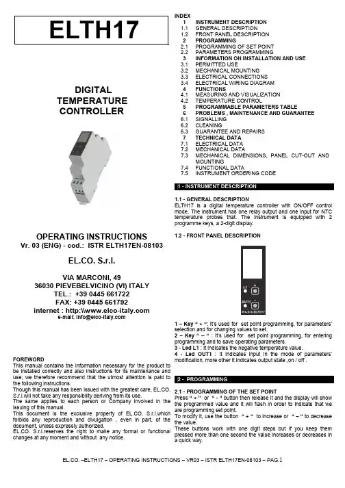
DIGITALTEMPERATURECONTROLLEROPERATING INSTRUCTIONS Vr. 03 (ENG) - cod.: ISTR ELTH17EN-08103EL.CO. S.r.l.VIA MARCONI, 4936030 PIEVEBELVICINO (VI) ITALYTEL.: +39 0445 661722FAX: +39 0445 661792internet : http:\\ FOREWORDThis manual contains the information necessary for the product to be installed correctly and also instructions for its maintenance and use; we therefore recommend that the utmost attention is paid to the following instructions.Though this manual has been issued with the greatest care, EL.CO. S.r.l.will not take any responsibility deriving from its use.The same applies to each person or Company involved in the issuing of this manual.This document is the exclusive property of EL.CO. S.r.l.which forbids any reproduction and divulgation , even in part, of the document, unless expressly authorized.EL.CO. S.r.l.reserves the right to make any formal or functional changes at any moment and without any notice. INDEXELTH17 1 INSTRUMENT DESCRIPTION1.1GENERAL DESCRIPTION1.2FRONT PANEL DESCRIPTION2 PROGRAMMING2.1PROGRAMMING OF SET POINT2.2PARAMETERS PROGRAMMING3 INFORMATION ON INSTALLATION AND USE3.1PERMITTED USE3.2MECHANICAL MOUNTING3.3ELECTRICAL CONNECTIONS3.4ELECTRICAL WIRING DIAGRAM4 FUNCTIONS4.1MEASURING AND VISUALIZATION4.2TEMPERATURE CONTROL5 PROGRAMMABLE PARAMETERS TABLE6 PROBLEMS , MAINTENANCE AND GUARANTEE6.1SIGNALLING6.2CLEANING6.3GUARANTEE AND REPAIRS7 TECHNICALDATA7.1ELECTRICAL DATA7.2MECHANICAL DATA7.3MECHANICAL DIMENSIONS, PANEL CUT-OUT ANDMOUNTING7.4FUNCTIONAL DATA7.5INSTRUMENT ORDERING CODE1.1 - GENERAL DESCRIPTIONELTH17 is a digital temperature controller with ON/OFF controlmode. The instrument has one relay output and one input for NTCtemperature probes that. The instrument is equipped with 2programme keys, a 2-digit display.1.2 - FRONT PANEL DESCRIPTION1 – Key “ +“: It’s used for set point programming, for parameters’selection and for changing values to set.2 – Key “ – “ : It’s used for set point programming, for enteringprogramming and to save operating parameters.3 - Led L1 : It indicates the negative temperature value.4 - Led OUT1 : It indicates input in the mode of parameters’modification, more other it indicates output state ,on / off .2 - PROGRAMMING2.1 - PROGRAMMING OF THE SET POINTPress “ + ” or “ - “ button then release it and the display will showthe programmed value and it will flash in order to indicate that weare programming set point.To modify it, use the button “ + “ to increase or “ – “ to decreasethe value.These buttons work with one digit steps but if you keep thempressed more than one second the value increases or decreases ina quick way.Exit from the Set programming mode happens automatically without pressing any button for round about 5 seconds, then the display will go back to the normal operating mode.The maximum value of set point that we can code, depends if weuse instrument’s or external probe and on minimum or maximumprogrammed differential.Instrument’s probe: min.-20°…..max +65°CExternal probe: min.-35°….max+98°CMaximum programmable value=set point + positive differentialMinimum programmable value=set point - negative differentialExample: with 5°C positive differential, the maximum programmable set-point will be of 60°C with probe on instrument and 93°C withexternal probe.With 5°C negative differential, the minimum programmable set-point will be of -15°C with probe on instrument and -30°C with external probe. 2.2 - PARAMETERS PROGRAMMING To enter the working parameters of instrument, we need to press “ + “ and “ – “ buttons simultaneously and to keep them pressed for 5 seconds, after whom the display will visualize the code that identify the first parameter and with “ + “ button will be possible to select the parameter that we intend to modify. Once we have selected the wished parameter, press “ – “ button , “ out1 “ led will light up and the display will visualize parameter’s code and its setting can be modified by “ + “ button . Once the whished value is programmed , press “ - “ button : the new value will be saved and the display will visualize once again the code of the selected parameter and “ out1 “ led will turn off. Working on “ + “ button then, it will be possible to select anotherparameter and modify it as described above. To exit the programming mode keep “ + “ and “ – “ buttons pressed simultaneously for 3 sec. till to exit the way ofprogramming. During the set-point programming (flashing display )we can not enter parameters’ programming.3.1 - PERMITTED USEThe instrument CANNOT be used in dangerous environments (flammable or explosive) without adequate protection. The installermust ensure that EMC rules are respected, also after the instrument installation, if necessary using proper filters. Whenever a failure or amalfunction of the device may cause dangerous situations forpersons, thing or animals, please remember that the plant has to be equipped with additional devices which will guarantee safety. 3.2 - MECHANICAL MOUNTINGThe instrument, in case 1 DIN Modules, is designed for mounting on DIN OMEGA rail.Avoid placing the instrument in environments with very high humidity levels or dirt that may create condensation or introduction of conductive substances into the instrument.Ensure adequate ventilation to the instrument and avoid installation in containers that house devices which may overheat or which may cause the instrument to function at a higher temperature than the one permitted and declared.Connect the instrument as far away as possible from sources of electromagnetic disturbances such as motors, power relays, relays, solenoid valves, etc.3.3 - ELECTRICAL CONNECTIONCarry out the electrical wiring by connecting only one wire to each terminal, according to the following diagram, checking that the power supply is the same as that indicated on the instrument and that the load current absorption is no higher than the maximum electricity current permitted.As the instrument is built-in equipment with permanent connection inside housing, it is not equipped with either switches or internaldevices to protect against overload of current: the installation willinclude an overload protection and a two-phase circuit-breaker,placed as near as possible to the instrument, and located in aposition that can easily be reached by the user and marked as instrument disconnecting device which interrupts the power supplyto the equipment. It is also recommended that the supply of all the electrical circuits connected to the instrument must be protect properly, using devices (ex. fuses) proportionate to the circulating currents. It is strongly recommended that cables with proper insulation, according to the working voltages and temperatures, be used. Furthermore, the input cable of the probe has to be kept separate from line voltage wiring. If the input cable of the probe is screened, it has to be connected to the ground with only one side.For the power supply it’s recommended to use an external transformer TRE, or with equivalent features, and to use only one transformer for each instrument because there is no insulation between supply and input. For the probe it is recommended to use an isolated NTC. We recommend that a check should be made that the parametersare those desired and that the application functions correctly before connecting the outputs to the actuators so as to avoid malfunctioning that may cause irregularities in the plant that could cause damage to people, things or animals. EL.CO. S.r.l. and its legal representatives do not assume any responsibility for any damage to people, things or animals deriving from violation, wrong or improper use or in any case not in compliance with the instrument’s features.3.4 - ELECTRICAL WIRING DIAGRAM PS. The neutral must always be connected to terminal A2ELTH1712-30VAC/DC4.1 - MEASURING AND VISUALIZATION The instrument only works with a NTC probe( 10K 25°C) Through “A” parameter is possible to choice whether working withthe probe on the instrument or with an external probe ( AI : instrument one– AE : external one). If during the setting of parameters we switch from external probe“AE” to the instrument’s one “AI”, it’s necessary to programme set-point once again, seeing that the working temperature range changes depending on the way of using the probe. The instrument allows the measure’s calibration, which can be used in order toadjust the device once again by “ H ” par , on the basis of application necessities. PS. Wait 3 minutes before checking the correct measurement oftemperature. 4.2 - TEMPERATURE CONTROL The regulating mode of instrument is ON/OFF type and it works on OUT output depending on the probe’s measure, on the Set Point and on the negative “ B “ or positive “ C “ operating differential.The faulty product must be shipped to EL.CO. with a detailed description of the faults found, without any fees or charge for EL.CO., except in the event of alternative agreements.7 - TECHNICAL DATA7.1 - ELECTRICAL DATAPower supply: 24 VAC/VDC, 200..240VAC +/- 10%Frequency AC: 50/60 HzInput/s: 1 input for isolated temperature probes NTC (103AT-2,10KΩ @ 25 °C)Output/s: 1 relay output SPDT 8A-AC1 (10A max. currentswitching),2A – AC15 25°CElectrical life for relay outputs: 100.000 op. ( AC1 nominal load)7.2 - MECHANICAL DATAHousing: Self-extinguishing plastic, UL 94 V0Dimensions: 1Din module, depth 64mmWhen it occurs an error for short circuit or interruption of the probe,the device is going to deactivate the output and the display will flashvisualizing two dashes “ - - “.Mounting: Enclosure on DIN OMEGA railConnections: 2,5 mm2 screw terminals blockDegree of front panel protection : IP 20Through “ D “ parameter we can regulate. operating mode ofoutput relay till reaching s et point : OFF “ D1 “ o ON “ D2 “ . Operating temperature: 0 ... 65°COperating humidity: 30 ... 95 RH% without condensationStorage temperature: -10 ... +65°C7.3 – MECHANICAL DIMENSIONS, PANEL CUT-OUT ANDMOUNTING [mm]Here below is a description of all the parameters available on theinstrument.Par.Descrizione Range Def.Note1AProbe rangeI : On the instrumentE : Outside-20….+65°C-35….+98°CI2 B Negative differential 0 – 9 °C 03 C Positive differential 0 – 9 °C 04 D Output relay operationD1=OFF / D2=OND1D2D15 H Probe calibration -5…..+5°C 0°C6.1 - SIGNALLINGError Signalling:Error Reason Action- - -The probe may beinterrupted or in shortcircuit, or may measure avalue outside the rangeallowedCheck the correctconnection of the probewith the instrument andcheck the probe workscorrectly7.4 - FUNCTIONAL FEATURESTemperature Control: ON/OFF modeMeasurement range NTC probe : -20….+65°C probe on theinstrument / -34….+98°C outside probeDisplay resolution: 1 ° COverall accuracy: +/- 0,5 % fsSampling rate: 12 samples per secondDisplay: 2Digit Red h 12 mmIn probe error status, the output will be off.Compliance: ECC directive EMC 89/336 (EN 61326), ECC directiveLV 73/23 and 93/68 (EN 61010-1)6.2 - CLEANINGWe recommend cleaning of the instrument with a slightly wet clothusing water and not abrasive cleaners or solvents which maydamage the instrument.7.5 - INSTRUMENT ORDERING CODEELTH17 a b cc d6.3 - GUARANTEE AND REPAIRSa : POWER SUPPLYThe instrument is under warranty against manufacturing flaws orfaulty material, that are found within 12 months from delivery date. 240 = 200..240 VAC24 = 24 VAC/VDCThe guarantee is limited to repairs or to the replacement of theinstrument.b : OUTPUT OUT TYPEThe eventual opening of the housing, the violation of the instrumentor the improper use and installation of the product will bring aboutthe immediate withdrawal of the warranty’s effects.R = Relay SPDT 8A-AC1In the event of a faulty instrument, either within the period ofwarranty, or further to its expiry, please contact our salesdepartment to obtain authorisation for sending the instrument to ourcompany.cc : SPECIAL CODESd : SPECIAL VERSIONS。

CLIO 电声测量系统ISA QC版中文使用简介目录一设备安装及调试 (03)1 硬件组成及系统需求 (03)2 软件安装 (04)3 主界面功能介绍 (05)4 系统校准 (06)二SPL测量及QC (07)1 接线方式 (07)2 MLS测试SPL (07)3 SPL数据的QC (10)三喇叭Q参数测量 (13)一.设备安装及调试:1.硬件组成及系统需求:HR-2000 ISA卡HR-2000 ISA卡适用于IBM兼容的PC机,要求具有8-BIT半长度ISA插槽和WIN95/98/ME操作系统。
需要使用DMA1或3,以及I/O地址300HEX或310HEX。
MIC-01或MIC-02 麦克风CLIO QC 功放&开关控制盒2.软件安装:I/O地址的选择:运行安装程序:出现如下画面,按照提示完成软件安装。
重启机器后,进入控制面板,选择“添加新硬件”选项。
选择添加“音频视频和游戏控制器”选择“从磁盘安装”,并选择CLIO软件的安装目录。
系统将找到HR-2000 ISA卡并给出现在使用的系统资源。
3.主界面功能介绍:4.系统校准:第一次运行CLIO系统,需要对系统进行校准。
校准时,需要短接HR-2000卡A 通道的输入和输出端。
双击CLIO WIN图标点击generator图标,系统将发出1KHz的音频信号。
点击多功能仪表图标当仪表读数为0.775时,表示输出输入正常,可以进行系统校准。
在File菜单选择Calibration开始自动校准,完成后即可进行项目测试。
二.SPL测量及QC1.接线方式:如上图,将HR-2000卡上的INPUT A和OUTPUT A分别与CLIO功放的TO CLIO 和FROM CLIO连接;将麦克风与CLIO功放的INPUT1连接;连接PC的打印接口与CLIO功放的控制接口;将脚踏开关连接到CLIO功放上.2. MLS测试SPL:进入外接设备控制对话框,确认所有选项正确.在主介面点击MLS图标:出现如下MLS测试画面:各功能键说明如下:开始MLS测试每次测试完毕自动保存结果不间断循环测试MLS运算对话框MLS设定对话框时间范围频率范围显示相位显示组延迟测试画面其它选项:输入通道选择信号输入输出通道Y轴单位进行SPL测试时选择dBSPL平滑度通常选择1/3平滑点按键进入MLS设定对话框sampling:选择测量取样频率。
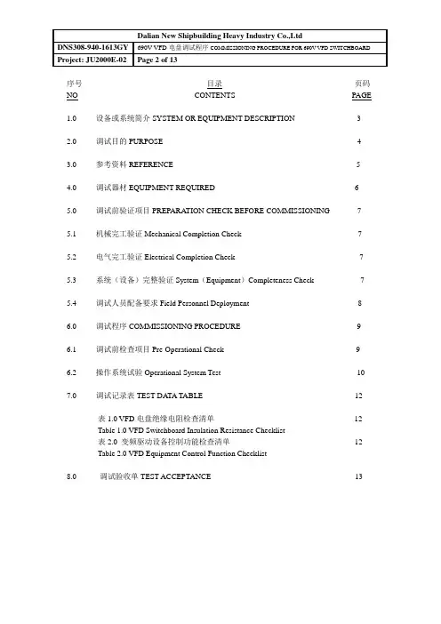
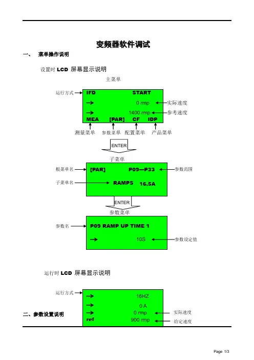
序号目录页码NO CONTENTS PAGE1.0 设备或系统简介SYSTEM OR EQUIPMENT DESCRIPTION 32.0 调试目的PURPOSE 43.0 参考资料REFERENCE 54.0 调试器材EQUIPMENT REQUIRED 65.0 调试前验证项目PREPARA TION CHECK BEFORE COMMISSIONING 75.1 机械完工验证Mechanical Completion Check 75.2 电气完工验证Electrical Completion Check 75.3 系统(设备)完整验证System(Equipment)Completeness Check 75.4 调试人员配备要求Field Personnel Deployment 86.0 调试程序COMMISSIONING PROCEDURE 96.1 调试前检查项目Pre-Operational Check 96.2 操作系统试验Operational System Test 107.0 调试记录表TEST DA TA TABLE 12表1.0 VFD电盘绝缘电阻检查清单12Table 1.0 VFD Switchboard Insulation Resistance Checklist表2.0 变频驱动设备控制功能检查清单12Table 2.0 VFD Equipment Control Function Checklist8.0 调试验收单TEST ACCEPTANCE 131.0设备或系统简介SYSTEM OR EQUIPMENT DESCRIPTION.690V VFD(变频驱动)电盘包括如下变流设备:The 690V VFD switchboard include the following facility.※ 4-整流器4-Rectifier※ 11-逆变器11-Inverter※ 6-制动断续器6-Braking chopper690V VFD电盘向如下交流负荷供电:The 690 volt VFD switchboard will feed AC power to the following:●4台绞车电机Four(4)unit Draw work motors.●6台泥浆泵Six(6)units Mud pump motors.●1台顶驱电机One(1)unit Top drive motor2.0调试目的PURPOSE2.1 确保690V VFD电盘的安装正确.To ensure proper installation of 690V VFD Switchboard system.2.2 证明VFD电盘的可操作性.To demonstrate the operational capabilities of VFD Switchboard.2.3 确保上述设备控制装置的功能.To ensure functionality of the above equipment control devices.3参考资料REFERENCE3.1 卖方文件VENDORS DOCUMENTATION3.1.1 安装检查及试验报告Installation Inspection and Test Reports.3.1.2 卖方制造厂证书Vendors Manufacturer Certificate.3.1.3 卖方调试程序V endor’s Testing & Commissioning Procedure.3.1.4 卖方设备清单V endors Equipment list3.2 工程图ENGINEERING DRAWING3.2.1 1572-E611-001 电气系统单线图OVERALL SINGLE LINE DIAGRAM3.2.2 1572-E611-004 变频驱动动力电气系统图VFD POWER SINGLE LINE DIAGRAM 3.2.3 1572-E611-005 变频驱动控制电气系统图VFD CONTROL SINGLE LINEDIAGRAM4.0调试器材EQUIPMENT REQUIRED4.1 万用表Multimeter4.2 500V高阻表Megger tester.4.3 双向无线电话Two way radios.4.4 1000V高阻表Megger tester.注意: 要求所有的测试仪器应在12个月的有效校准期内。
CTX690 Network Tone andProbe KitUSER MANUALIntroductionCongratulations on your purchase the CTX690. This Network Toner and Probe Kit is designed specifically for locating and tracing cables on inactive oractive networks, and live or dead phone lines, as well as coaxial video cabling systems. Today’s media networks have a combination of twisted pair data, telephone voice, coax and security/alarm video wiring. It provides 2 selectable powerful Net and Tel tones allow cabling installers, Datacom/Telecom technicians directly plug into an active networks, patch panel, wall outlet or live phone line, makes it easy to quickly isolate the right cable in the equipment closet, and locating an unlabeled network cables during installation and troubleshooting.Meter Description1. Net Toner2. F Male to Alligator ClipAdaptor (Optional)3. Trace Button/Volume Adjust4. Probe Tip5. RJ45 Connector6. RJ11 Connector7. Alligator Clips8. Mode Function SwitchesOperating InstructionsNote: To extend battery life, remember to turn off the probe and transmitter after tracing the cablesSelf Check•Turn the probe on and set the transmitter to TONE.•The RED LED on both units will light up. Replace the batteries if they do not.•Touch the probe to the transmitter wires and check for the generated tone..Cable/Wire tracing“Tone” mode transmits 2 selectable powerful net tones to allow the userto quickly and accurately trace wires or cables directly in connection with an active Network Hub, Switch, Router and Live Telephone LineSystems.Set the left slide switch in the “Tone” position, the tone LED constantlyflashing to indicate the “Tone” mode is on.I. Locating & tracing RJ45 cables or wall outlets on inactive and activenetworks on switch, Hub, router, patch panels, termination blocks orhidden within bundles.1. Use the RJ45 plug cable for tracing inactive & activenetwork cabling systems.2. The RJ45 plug cable can be used to connect an RJ45 network jack to betraced or use an optional RJ45 inline coupler to connect RJ45 plug andRJ45 plug of the cable to be traced.3. Select the right slide switch for an alternating tone (parallel or crosstone). When select parallel tone, 3/6 and 4/5 LEDs will be flashing.Select cross tone, 3/6 LED will be light on.4. Use the Net Probe to find the cable you have connected to, when thetip of the Net Probe touches the right wire/cable, the tone will be atits loudest, with a bright red signal light.5. Move left slide switch to “OFF/LINE” position, the tone LED turns off indicating that the tone is off.II. Tracing Live or Dead Telephone Lines1. Use the RJ11 plug cable for tracing dead & live phone lines.2. The RJ11 plug cable can be used to connect to aRJ11/RJ11 phone jack to be traced or use an optional RJ11 inlinecoupler to connect RJ11/RJ11 plug and RJ11/RJ11 plug of the cableto be traced.3. The far end of the cable being traced can be located by using the Net Probe.III. Locating individual wire, pairs with alligator clips.1. Connect the black alligator clip to the ground and then connect the redclip to the wire to be traced.2. Connect alligator clips across the line or attach one clip to ground andthe other clip to one wire of a cable or pair to be traced.IV. Coax Cable Tracing1. Tracing terminated coax cables∙Using optional F-male to alligator clips adapter.∙Connect the F-male adapter to the F-female connector of the Coax cable to be traced.∙Connect red clip of the adapter to the red clip on the toner.∙Connect black clip of the adapter to the black clip on the toner.2. Tracing un-terminated coax cables∙Connect the red clip to the outer shield and black clip to theground or to the center conductor.V. Isolating individual wire pairs for exact pair identification1. In “TONE” mode when both clips (red & black) connected to the pair,and move right slide switch to the 4/5 Cont LED position can be usedon a dead line to identify and verify having found both clips of a pair.2. When touching the wire together, momentarily shorting the far end of acable pair.3. The audible tone will be disappearing when you short the correct pair onthe far end. On the Net Toner the 4/5 Cont LED will turn off and theaudible tone will change the cadence of the tone generatedsimultaneously, indicating the pair has been found.Checking Status and Polarity of Phone LinesIndicates proper line polarity and status by lighting its LED eitherGreen or Red.Do not connect to circuit carrying AC voltage in OFF/LINE mode.1. Move the left slide switch in OFF/LINE position.2. Attach either the RJ11 plug cable for checkingLine 1 and Line 2. Or the alligator clips forchecking Line 1 only to the connection to betested.3. Connect black clip to Tip (+) and the red clip toRing (-) or one clip to each wire of the pair ifdesignation is unknown.•If the green light up indicates the polarity iscorrect/normal. It means that the black clip connects to Tip (+).If thered light up, it means the clips are reversed.• A bright LED indicates the line is not in use.• A dim LED indicates the circuit is in use.•Flickering red & green indicates presence of ACpower or ringing line.4. Dial the line to be verified. If the Net Toner is connectedto the correct line, the Line 1 LED will flickering red andgreen.5. Monitor the line; move the slide switch to “Cont”position, this will terminate the call to confirm theidentification.Testing Continuity of a Cable/Wire CircuitUse only on non-energized circuit.Do not connect to AC or DC voltage circuit in “Cont” mode.Before connecting to an unknown cable/wire to the NetToner in “Cont” mode, use the OFF/LINE mode to check andensure that cable/wire are not powered. Connecting the livepowered cable in “Cont” mode may damage the Net Toneror cause erroneous results.1. With the left slide switch in “Cont/Talk” positionand right slide switch in “Cont” position.2. Connect the red and black clips to both ends of thecable/wire that you want to test.3) The “Cont” LED indicator will light green. Bright greenindicates a low resistance path. Dim green indicates ahigh resistance path. No Light, indicates an opencircuit.4) When a short circuit is detected, the “Cont” LED indicator willlight green.5) Move th e left slide switch to “OFF/LINE” position whenfinished to avoid draining battery of clips touch duringstorage.Supply Talk Battery PowerThe talk battery mode should not be used with voltage present.The Net Toner will supply power to operate handsets. This feature particularly useful when two installers are working at terminal panels, and must have at least one identified pair connected between them. This model allows the installers to commutation using their handsets.*Please use a new battery to enhance talk power supply.1. With the left slide switch in the “Talk/Cont” position and the right slideswitch in the “Talk” position.2. Using the red & black clips connect the handsets in series as shownin the diagram.3. Place both headsets “OFF HOOK” or “Talk” position to establishcommunication.4. When finished, move the left slide switch to “Off/Line” position to avoiddraining battery. No power drain in “Cont/Talk” mode with clip openbut the clips touching during storage could drain the battery.Probe Functions and Indications(A) Tone tracing1) Set the〝Trace/Hub blink〞 selector to〝Trace〞↓position.2) Push〝Trace〞 button and the probe end becomesactive.3) Hold〝Trace〞 button to trace a line or plug theprobe’s RJ45 jack into a wall outlet or patch panelport using a jumper cable.4) The tone is loudest when the tip of the tracer isnear and parallel to the cable carrying the tonesignal.*Application Hint: To detect tracing tone signal at patch panel.For the best signal, usinga patch cable, one endconnect to Net Probe ProRJ45 jack, then use theother end patch cableconnect or touch thepatch panel port.(B) Signal strength LEDTouch the tip of the Probe to the insulation of each suspectwire/cable, when the tip touches the right cable, the tone willbe at its loudest and the〝Signal〞LED will turn on. (Youmay turn the volume down as the tip gets nearer to the rightcable to help distinguish between the cables and the tiptouch.)(C) Flashlight1) Set the left side light switch to〝ON〞↑position toturn the flashlight on to help you to find the target indark field.2) Set the switch to〝OFF〞↓position to turn off the light.(D) Ear Jack:In noisy environments, 2.5 mm headphone may be pluggedinto the ear jack on the right side of the Net Probe Pro, besure to fully seat the plug into the jack.The speaker is muted to avoid disturbing people nearly.(E) Hub Blink and Link Mode (Hub blink mode LED blink Yellow)To locate an active Ethernet port drop on Hub/Switch orRouter and identifies an unknown RJ45-outlet for activeEthernet.The probe will blink the corresponding port LED ofthe Hub or Switch at the other end for fastidentification.The feature provides a simple and effective way toidentify Switch, Hub port assignment on activenetworks; it’s perfect for tracing active network cablelocation.1. Hub BlinkThe probe will send signal to make the connectedPoE/Ethernet port blinking at a set frequency, this willenable help the installers to easily and quickly find theconnected port for an active Ethernet cable.1) Connect the probe’s right side “ Trace-Net” RJ45jack to a cable or network outlet at a room orworkstation for which the Ethernet port is to belocated.2) Set the rig ht side switch to "Hub Blink mode" ↑position, Blink Hub mode LED begin blinking Yellowand start to send a link pulses to connect the port ona Ethernet/PoE Switch or Hub.If an Ethernet link is active on the cable, theprobe begins blinking the link indication port ofthe Hub or Switch at the far end and Active LinkGreen LED will be on simultaneously.If no active connection was detected, the Active Link LEDwill be off.2. Link IndicatorIf an Ethernet link is active on the cable or networkoutlet, the Link Green LED will be blinking.Simultaneously the tester begins blinking with thelink indicator on a port of Hub/Switch at the far end.This will assist with troubleshooting forquickly determine whether an unknownoutlet or cable is connected to an activeHub/Switch.If an Ethernet line at far end, Hub is active on thecable the Link LED will be blinking.If no active connection was detected, the Link LED will beoff.NOTE: In Hub blink mode, if a cable is connected to remote unit or connected to a STP cable, this will cause the Link LED blink.(G) Replacing Tip1) Grasp the tip and gently turn it counterclockwiseuntil it separates form the probe body.2) Replace the old tip with acompatible new tip and reversestep1. Note: Do not overtightenthe tip.(H) Power / Battery Low1) Both units require onestandard or alkaline9V battery. Slide backthe battery cover toreplace new battery.2) When a low battery is indicated onunit, change the battery immediately,as continuing to test with a lowbattery may produce inaccurateresults.Copyright © 2019 TriplettSpecifications。
According to ATEX Directive 94/9/ECPowerful IND690 technologyfor hazardous areasTough but sensitive –even in hazardous areasTo see and be seen – BIG WEIGHT ®display.Bright, fast and clear, this active dot matrix display shows the result of the weighing operation. Readable from a distance, the BIG WEIGHT ®display is ideal for professional users. Protected behind scratch-proof safety glass the display will not dim over time.•Complies with ATEX Directive 94/9/EC for potentially explosive atmospheres•Protection class IP69K – ideal for the toughest working conditions•BIG WEIGHT ®display – bright, with graphics capability, even in poorly lit areas•Excellent performance – with software pacs to enhance further •Easily integratedIND690 displays say it loud and clear. Available in many langua-ges, to guide the user easily and reliably.1 terminal,2 models,3 types of installationSure to be just right for your purpose. Protected to Class IP69K and made of stainless steel, the bench model is also ideal for wall mounting, thanks to the adapter that allows it to be tilted andturned. Cables can be hidden underneath – the best protection against dirt and damage. The built-in model is also uncompromi-sing, featuring fast, universal installation, and maximum accessi-bility. Front side also IP69K + stainless steel.Keypad has a nice, substantial feelThe generous, easy-to-clean membrane with smooth surface and raised, embossed buttons meets all requirements related to ergonomics, hygiene and durability.A connectable PC keyboard (MFII/PS2) or barcode reader makes data entry even faster and easier.Interfaces for secure connectivityThe basic version is ready to go with an RS232 data interface (e.g. to connect a printer). Up to 8 more interfaces can be added easily and inexpensively for still greater modularity and flexibility.100% leakproof and yet open on all sides. Data and pulses for other devices.BIG WEIGHT ®is a registered trademark of Mettler-Toledo (Albstadt)GmbH. German Patent 197 32 659. European Patent 0 895 071.Relationship between categories and zonesHazardous areas are frequently subdivided into different zones according to the degree of the hazard. Depending on the zone, different categories of electrical equipment must be used.Category Specified type of Permitted for use Also permitted IND690xx hazardous in Zone for use in Zone permittedatmosphere for useGas/air mixture3Or vapor/air 2•mixture or mist3Dust/air mixture22•EN 1127-1:1997Since 1998 METTLER TOLEDOhas operated an approved qualityassurance system according toATEX Directive 94/9/EC for theproduction of instruments inten-ded for use in hazardous areas.The frequency of occurrence of an explosive mixtureHow frequently is an explosive atmosphere expected? The answer to this question is used to define separate zones in a factory or plant:Hazardous, explosive atomospheres are presentrarely and brieflyDue to gases, vapors, mists Zone 2Due to dusts Zone 22The more frequently an explosion hazard is expected to occur, the higher the safety requirements for instruments used. The ATEX Directive 94/9/EC defines categories for the various safety levels.Safety level of instrument Category For use in ZonesVery high level of safety10, 1, 2, 20, 21, 22High level of safety21, 2, 21, 22Normal level of safety32, 22Connection to the scale by weightDisplay and data entryStandard functionsHousings/ambient conditionsData interfacesGeneral dataOrdering informationDimensions (mm)IND690 bench modelIND690 built-in modelAccessories Multi-Range Application Terminal IND690xxAccessories application terminal IND690xxSubject to technical changes©Mettler-Toledo GmbH 22012876.Printed in GermanyDigital I/O interfaces outside hazardous areasThe 4-690 and 8-690 relay boxes are not designed for use inpotentially explosive areas. They may only be used in non-hazar-dous areas, or in hazardous areas if additional safety measuresare taken.Digital I/O Interfaces Order-No.4I/O-690 4 input/4 output22 011 965interface, 19-pole fem. conn.Relay box 4-690Relay box with 4 input/22 011 9674 output, for connectionto 4I/O-690Cable, 10m, for connecting00 504 4584I/O-690 with the relay boxMale connector, 19-pole00 504 461Relay box 8-690 Relay box with 8 input/22 011 9688 output for connection toRS485/422-690Analogue outputAnalogue Out-690 Analogue output22 011 9660-10V, 0-20mA,4-20 mA, 5-pole fem. conn.Cable for analogue output,00 204 930open end, 3mD/A male connector, 5-pole00 205 538Certifiable memoryAlibiMemory-690 Storage for metrologicallyrelevant records. Replacesthe alibi printer in certifiableapplications. 22 011 950Mechanical accessoriesWall bracket for bench model, stainless steel22 011 980Floor stand for bench model, stainless steel22 011 981Stand base stainless steel22 011 982Sales and service:ConformityQuality certificates。
E调试软件I E c o u t使用说明HEN system office room 【HEN16H-HENS2AHENS8Q8-HENH1688】IEC61850之调试软件IEDScout配置使用说明1.软件配置2.IEDSout不用安装直接复制到目录下运行文件夹内即可,第一次运行会提示无法找到配置文件,此时选”是”在弹出的框口中选择文件夹内的即可。
软件运行后进行连接配置:3. a.点击“options”?configuration或者直接点击弹出配置界面。
4.5. b.在Servers配置目标机器IP地址6.如果需要的server已经存在则不需要建立,或在IP Address中更新需要的IP即可,如果不存在点击7.“New”弹出新建窗口。
8.9. Name of new server:任意(填写自己易识别的名字即可)10. IP Address: 填写要连接的目标机器IP地址(如MOXA工控机11.c.配置本机IP12.填入本机IP(即运行IEDscout的电脑IP地址)13.14.d.其他保持默认值即可,点”apply”“OK”保存设置返回主界面即可。
15.搜索目标服务器建立连接a.点”Actions”?”Discover”或工具栏弹出搜索框。
b.选择相应的服务器,点击”Connect”搜索目标服务器,如果找到会自动返回主窗口显示目标服务器数据目录。
c.d.e.如果在连接过程中无法找到服务器可以点击“Actions”?”Messages”或查看相当的连接信息排除是否设置不正确16.查看数据17.连接建立后显示的数据目录结果标识如下图:18.19.a. 在连接建立后,主窗口显示目标服务器提供的所有数据目录结构,查看某一节点数的数据请双击该节点弹出20.数据结构窗口查看具体数值。
21.22.b. 数据节点有GGIO,SPC,LLN0,LPHD0等。
23. LLN0,LPHD为设备信息描述数据,描述设备的工作状态,产品类型等。
电气自动化及仪表安装调试规范唐山电通科技2021年9月16日建立电气施工规范一、安装程序、工艺及检验1).施工前要做如下准备:1.1由技术负责人组织参加施工的技工认真熟悉施工图纸及相关设计文件、标准规范,掌握设计意图及设计要求,对图中所选用的电气设备和主要材料进行统计。
做好施工图纸的审查、会审,参加设计交底及图纸会审。
1.2按施工作业计划备齐施工用料及施工机具。
1.3与设备材料部及质量管理部一起进行工程设备及材料的检验工作,要求设备、材料的规格、型号、数量应与图纸一致,附件、备件、质量合格证及技术文件齐全,同时应符合规范要求,按照要求及时进行施工前的报验,并作好检验记录。
1.4根据项目特点,组织学习安全规程及规章制度,开工前对施工人员进行全面的安全技术交底。
施工前组织与土建专业进行工序交接,核实土建工程是否达到电气施工要求,内容如下:(1)屋顶、楼板施工完毕,不得渗漏。
(2)室内地面的基层施工完毕。
(3)配电室门窗安装完毕,具备封闭条件。
(4)设备安装后不能再有可能损坏已安装设备的其他工作。
(5)混凝土基础及构架达到允许安装的强度,设备支架焊接质量应符合设计要求。
(6)施工设施及杂物须清除干净,并有足够的安装用地,施工道路畅通。
当主车间土建施工达到如上即可进行电气安装。
安装前的检查工作(1)清扫和清理电气设备、元件的赃污、缺陷,更换损坏的零部件;(2)所有可动部件、零件应动作灵活、无卡住、粘滞或松动现象;(3)所有接线紧固件齐全,已接线的螺钉应紧固;(4)电气设备的安装紧固件、构架、钢管及接头、连接件、导电装置、支架等非带电金属部分均应镀锌或涂漆防腐或采取镀锌制品;2).电缆桥架的安装。
为了保证投产后控制信号的稳定传输,要求将动力线与控制线分开,所以电缆桥架通常为单层桥架。
当桥架在车间墙边安装时,一般采用向墙边地面打膨胀螺栓固定的方式固定桥架支架。
如果电缆桥架需要延伸到厂房中心部位,这时采用在房梁上打膨胀螺栓,固定一段向下引出的型钢,再在型钢上焊上托架,对电缆桥架进行支撑。