蒂森控制板操作器说明
- 格式:docx
- 大小:170.92 KB
- 文档页数:40
伺服门机使用说明(V2.2)一、外型尺码二、面板布局X1X2X3X4+12V AC1注:1.SW 开关拨向上为ON ,拨向下为OFF 。
SW 在输出灯灭时拨动有效。
2.TR1~TR2顺时针方向为加减速时间增大方向,开关门速度变慢。
3.TR3~TR4顺时针方向为力矩增加方向。
三、接线四、接口说明1.输入输出用途端口标识说明输入X1开门动作,闭合有效X2关门动作,闭合有效X3备用X4慢关门动作,闭合有效输出MC-M1-M2开门到位,M1常闭,M2常开MC-M3-M4关门到位,M3常闭,M4常开MC-M5-M6堵转故障检出,M5常闭,M6常开M7-M8备用2.输入逻辑优先次序(1) 慢关门 (2) 开门 (3) 关门3.输入端子的接线方法控制信号可以使用外部电源或内部电源+12VX1X2X3X4XC 0V外部电源接线方法内部电源接线方法1+12VX1X2X3X4XC 0V 内部电源接线方法2五、运行原理开门曲线(达到速度上限)关门曲线(未达到速度上限)关门机械定义说明(1)终端开门到位区内为开门终端区,在开门终端区内输出开门到位信号。
关门到位区内为关门终端区,在关门终端区内输出关门到位信号。
(2)动作门机在正常定位移动或蠕动时的状态。
关门达到关门计算终端位置或开门达到开门计算终端位置以后蠕动频率继续运行,直至堵转发生。
动作状态的力矩限制由P6.01参数设置。
(3)保持在非关门终端位置没有开关门信号时的零速锁定状态,或在开关门终端区堵转发生后时的状态。
关门堵转保持状态下的力矩上限由P6.02设置。
(4)堵转门机在开门过程中力矩指令达到最大力矩上限;或者在关门过程中力矩指令超过关门堵转检出阀值(P6.03)且持续时间超过堵转检出时间(P6.04),则堵转状态检出。
关门时在关门终端外检出堵转,则输出堵转信号,转为零速保持状态,记忆故障位置,等待开门信号;在关门终端内检出堵转,不输出堵转信号,进入关门保持状态。
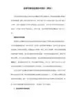
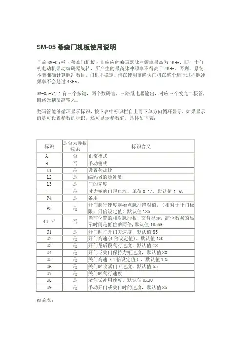
DIAGNOSTIC UNIT IFunction 01 00 Display of error stack as per:05.00显示故障堆栈 Example:ErrorExplanationWeighting BW任务特N emergency stop 紧急停梯 landing 楼层S stopping 停止undefined 未定义M spontaneous message 自发信息 explanations from page 21 解释21页B lift blocked 电梯被锁定ZZ Number of marking flag 标志编号..B operation phase 运行阶段Significance: Frequency levels of error: 含义:故障频繁度Level 1 infrequent 1度不频繁1) can be suppressed with switch 6S1 on circuit board MZ or with switch S5 on circuit board MZ1.1) Dependenton the function involved, reset can either mean emergency stop following by adjusting run or stopping of the lift installation2) Handshake is defined as cyclical data exchange (telegram) between two data carriers.1) SR module can be masked out via teach-in mode function AF 0d. Running-open operation and re-levelling with door open is not possible.1) Error from TCI work program 03.89/7 – no longer used.2) Error 35 00 and 3b 00 can no longer occur from work program 02.87/4 and error 36 00 can no longer occur from 06.95/25.1) SR module can be masked out through teach-in-mode function AF 0d. N Runnin-open operation andre-levelling with open door not possible.2) 0C 04 to 0C 0C leads also to stopping, if not provided otherwise in the lift-specific EPROM !1) If errors 65 00 to 74 00 occur more than 3 times, error 4F 00 will follow afterwards, which leads tospontaneous message and stopping1) DSP is the digital signal processor in the CPI controller2) Handshake is defined as cyclical data exchange (telegram) between two data carriers.Explanations of the existing error code numbers04 NN TCI control – Interrogation of ZSE solenoid switchesNN is represented as a hexadecimal number; in the event of errors, it indicates the number of ZSE switches (no other than the ZSE switch of the car position may be actuated).04 00 applies to ZSE 25 t o ZSE 3104 00 applies to ZSE 17 t o ZSE 2404 00 applies to ZSE 9 to ZSE 1604 0C applies to ZSE 1 to ZSE 8Example: 0 4 0 CHexadecimal number 0C∣∣Binary number 0 0 0 0 1 1 0 0∣∣∣∣∣∣∣∣assigned ZSE switch 8 7 6 5 4 3 2 1The example shows that ZSE switches ZSE3 and ZSE4 (in 3. and 4. landing) havebeen activated. (Also compare hexadecimal code in part 4, page 2)04 NN TCM control – Interrogation of ZSE solenoid switchesIf ZSE switches are closed in the third and fourth landing, the TCM controlwill file two errors: 04 03 und 04 0406 XX TCI control–Door locking not possible (from work program version 08.91/9)The lift will be put out of service for 15 min. after 3 unsuccessful doorlocking attempts. A new locking attempt will be initiated after expiry ofthis period of time.XX = StandortDoor variant – hinged door:A new locking attempt will also be made within these 15 min. after opening ofthe landing door (TK open) and closingit again (TK closed).Door variant D4 (with mechanical locking device)A start attempt will be enabled within 15 min., as soon as the controlreceives the bolt contact.06 XX TCM control–Door locking not possibleIf open bolt contact is recognized in the command chain preceding theposition the following error will follow14 XX (XX = bolt contact main side)18 XX (XX = bolt contact rear side)09 NN Car will be blocked in the landing >4 minExample LED Signal name (LED display on diagnostic unit Irow A)0 KKD0 LSD1 KK O.K.1 LS O.K.0 TSUD0 TSOD0 TSU1 TSO activatedFor LEDs and signal names see Operating Instructions of Diagnostic Unit I,function 05 00, column 0d (display of predefined memory locations, from page25).19 NN Door zone not detectedExample 1 9 C 81 VR1 A5A0 TO0 TU1 FL0 FS0 FO0 FUIn the operation phase STOP (lift at standstill), the CPU recognizes that thedoor zone calculated from the landing vanes was left.For LEDs and signal names see Operating Instructions Diagnostic Unit Ifunction 05 00, column 05 (display of predefined memory locations,from page25)1d NN Emergeny stop (wrong run direction)No run direction or both run directions were produced with the run contactoractivated and the brake disengaged.For LEDs and signal names see Operating Instructions, Diagnostic Unit I,function 05 00, column 05 (display of predefined memory locations from page25).In case of error 1d C8 the processor outputs the signals VR, A5A and FL (butwithout run directions); compare above representation of error 19 NN1E NN Deceleration not effectiveBinary display of car positionIt will be examined whether deceleration has been initiated already onreaching the marked terminal landing vanes.The position is indicated by the five bitst 20 to 25 as binary number.Example:27FO (run direction UP)26FU activated (run direction DOWN)252423Position (hexadecimal number converted into22binary number)211 201 E 9d: bits 20 to 27 stand for landing 29, therefore only run direction UPexists, since 26 = 0 and 27 = 1, and consequently 9 d will follow.Function 02 00 Display of order number (fromTCI work program version 06.88/6 and with TCM)显示定单号码(从TCI 06.88/6版工作程序起以及TCM梯)Example: Order No.: 27 70 06 42 10∣∣∣∣∣LED 5 12 3 10 1B A B A BFunction 03 00 Position indicator (decimal)楼层显示(十进制)Function 04 00 Operation phaseFunction 05 00 Display of specified memory locations1) Set function 05 00 with program selector wheel2) Press start-stop button3)Select desired column in 7-segment display with program selector wheelExample: Column 0d is desired. For example, select 0C 0d in 7-segment display, then left LED row B applies to column 0C and right LED row A applies to column0d, etc.4) Interrogate LED display (compare overview and signal description)5) Exit: press start-stop button for longer than 2 s.The LEDs listed in the table will light on selecting the respective column (Col) :1) Error markingExtension of columns for TCM control with MC1 or MC2 circuit boards1) pulses are counted dependent on the run direction (20 to 27 is displayed in LED row A/B)1) will be displayed as hexadecimal number in LED row A. Example: 09 in LED row A LEDs 0000 1001 light up2) displays last failure before current failure cause column 2C. Is displayed in hexadecimal numbers as in column 2C1) MF3 (VA) stands for circuit board MF3 with double-sided insertion 1) MF3 (VA) stands for circuit board MF3 with double-sided insertion1) MF3 (VA) stands for circuit board MF3 with double-sided insertion1) not assigned currently.Function 07 00 Display of parameters of CPI controller (only with TCM controls) 显示CPI。

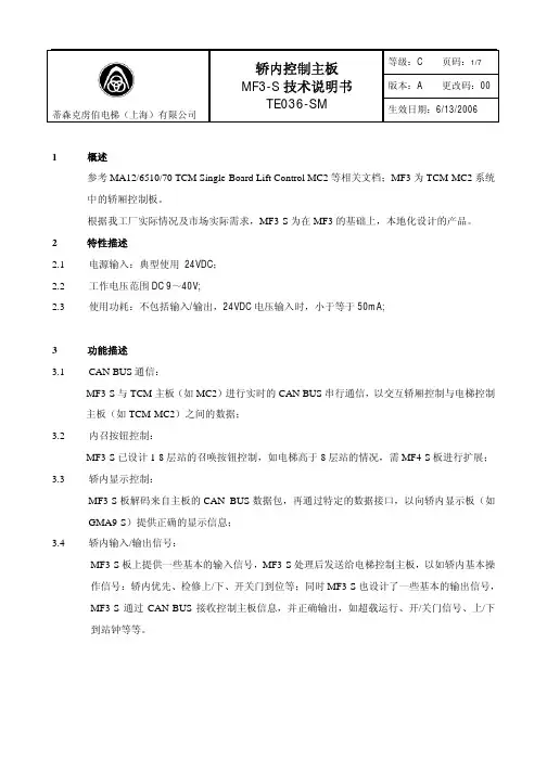
版本:A 更改码:00 蒂森克虏伯电梯(上海)有限公司MF3-S 技术说明书TE036-SM生效日期:6/13/20061 概述参考MA12/6510/70 TCM Single-Board Lift Control MC2等相关文档;MF3为TCM-MC2系统中的轿厢控制板。
根据我工厂实际情况及市场实际需求,MF3-S 为在MF3的基础上,本地化设计的产品。
2 特性描述2.1 电源输入:典型使用 24VDC ;2.2 工作电压范围DC 9~40V;2.3使用功耗:不包括输入/输出,24VDC 电压输入时,小于等于50mA;3 功能描述3.1CAN BUS 通信:MF3-S 与TCM 主板(如MC2)进行实时的CAN BUS 串行通信,以交互轿厢控制与电梯控制主板(如TCM-MC2)之间的数据;3.2 内召按钮控制:MF3-S 已设计1-8层站的召唤按钮控制,如电梯高于8层站的情况,需MF4-S 板进行扩展;3.3 轿内显示控制:MF3-S 板解码来自主板的CAN BUS 数据包,再通过特定的数据接口,以向轿内显示板(如GMA9-S )提供正确的显示信息;3.4 轿内输入/输出信号:MF3-S 板上提供一些基本的输入信号,MF3-S 处理后发送给电梯控制主板,以如轿内基本操作信号:轿内优先、检修上/下、开关门到位等;同时MF3-S 也设计了一些基本的输出信号,MF3-S 通过CAN-BUS 接收控制主板信息,并正确输出,如超载运行、开/关门信号、上/下到站钟等等。
版本:A 更改码:00蒂森克虏伯电梯(上海)有限公司MF3-S 技术说明书TE036-SM生效日期:6/13/20064 线路板安装及布局图版本:A 更改码:00蒂森克虏伯电梯(上海)有限公司MF3-S 技术说明书TE036-SM生效日期:6/13/2006版本:A 更改码:00蒂森克虏伯电梯(上海)有限公司MF3-S 技术说明书TE036-SM生效日期:6/13/20065 MF3-S 软件配置MF3-S 软件配置与MF3板完全兼容,即配用27C256存储芯片,工作程序根据最新释放版本,其中前后门由软件来定义,于我工厂电气车间进行烧录;版本:A 更改码:00蒂森克虏伯电梯(上海)有限公司MF3-S 技术说明书TE036-SM生效日期:6/13/20066 MF3-S 接口定义列表6.1接口类型中,表示方法: “I ”- 输入;“O ”-输出;“C ”- CAN BUS ;“M ”- 综合;“P ”- 电源信号功能信号名称端口定义 接插件 类型 接口 类型备注1-8层召唤按钮控制 Car call button 1-8层按钮输入 0V+24 V1-8按钮灯输出 X51:3-X58:3X51:4-X58:4 X51:1-X58:1 X51:2-X58:2 CH2.54 × 4I轿内优先控制Preference V 0V+24V X34:3 X34:4 X34:1 CH2.54× 4 I满载信号Occupied B 0VX15:1 X15:2 CH3.96 × 2 I 超载Overload UB 0VX9:2CH3.96 × 2 I开门按钮Door opening Button OT 0V+24V X59:3 X59:4 X60:1 CH2.54 × 4 I关门按钮Door closing button UT 0V +24VX60:3 X60:4 X60:1 CH2.54 × 4 I再平层传感器Re-leveling Sensor LN +24V0V X42:2 X42:1 X42:3 CH3.96 × 3 I检修上/下Insp. op UP Insp, op DOWN IF IFO IFU 0VX40.1 X40.2 X40.3 CH3.96 × 3 I安全触板/光幕Articulated Light barrier d. KK 0V L TX5:1 X5:2 X5:3 CH3.96 × 3 I光电选层器Selector Sensor LK +24V0VX2:2 X2:1 X2:3 CH3.96 × 3 I后门安全触板/光幕 Articul. lever Rear Light barrier KKD 0V L TDX6:1 X6:2 X6:3CH3.96 × 3I版本:A 更改码:00蒂森克虏伯电梯(上海)有限公司MF3-S 技术说明书TE036-SM生效日期:6/13/2006MF3-S 接口定义列表(续一)信号功能信号名称端口定义 接插件 类型 接口 类型备注根据工作程序指定的备用输入EBS10V ZTK X41:1 X41:2 X41:1 CH3.96 × 2 I前门开门到位Door open switch (Front)TSO 0V X3:1 X3:2 CH3.96 × 2 I后门开门到位Door open switch RearTSOD 0V X4:1 X4:2 CH3.96 × 2 I备用输入EES2 0V X47:1 X47:2 CH3.96 × 2 I召唤屏蔽使能Coding of calls AT 0V+24VX49;3 X49:4 X49:1 CH2.54 × 4I轿内显示板数据端Dataindicator MA/3TSData to MA X35M前门开/关门信号Door open/close .sig. (m.door)TU TO X43:1 X43:2 CH3.96 × 2 O后门开/关门信号Door open/cLose signal, rear side TUD TOD X45:1 X45:2 CH3.96 × 2 O前门强迫关门信号 Nudging main side ZTZ +24V X44:2 X44:1 CH3.96 × 2 O 后门强迫关门信号 Nudging rear side ZTZD + 24V X46:2 X46:1 CH3.96 × 2 O下到站钟输出 Gong, BOTTOM I < 600 mA GU +24V X22:2 X22:1 CH3.96 × 2 O上到站钟输出 Gong, top I < 600 mAGO + 24VX19:2 X19:1 CH3.96 × 2 O消防警示钟Fireman’s horn I < 600 mAFEH + 24V X21:2 X21:1CH3.96 × 2O版本:A 更改码:00蒂森克虏伯电梯(上海)有限公司MF3-S 技术说明书TE036-SM生效日期:6/13/2006MF3-S 接口定义列表(续二)信号功能 信号名称 端口定义 接插件 类型 接口 类型备注紧急呼叫信号 Call alarm I < 600 mA RW + 24V X20:2 X20:1 CH3.96 × 2 O备用3 RES3 I < 40 mA RES3X62:2 X62:1 CH3.96 × 2 O备用4 RES4 I < 40 mA RES4 +24VX63:2 X63:1 CH3.96 × 2OCAN BUS 总线 CAN bus HIGH CAN bus LOW Front + rear coding CAN-H CAN-L 0V COD X64:4 X64:3 X64:2 X64:1 CH2.54 × 4C信号同X65CAN BUS 总线 CAN bus HIGH CAN bus LOW Front + rear coding CAN-H CAN-L 0V COD X65:1 X65:2 X65:3 X65:4 CH3.96 × 4C信号同X64电源电压Voltage supplyVoltage supply+24V 0VX1:1 X1: 2 CH3.96 × 2 P Voltage supply Command accept + 24V 0V X31:1 X31:2CH3.96 × 2P批 准审 核编 制。
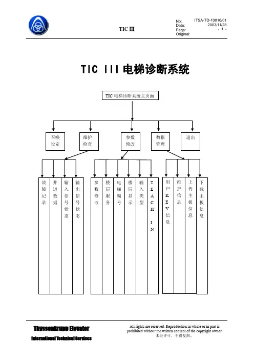
SM-05蒂森门机板使用说明目前SM-05板(蒂森门机板)能响应的编码器脉冲频率最高为4KHz,即:由门机电动机带动编码器旋转,所产生的最高脉冲频率不得高于4KHz。
否则,系统不能准确计算脉冲数目,门机不稳定。
请在使用前确认门机在整个运行过程脉冲频率不会超过4KHz。
SM-05-V1.1有三个按键,两个数码管,三路继电器输出,对应三个发光二极管,四路光耦隔离输入。
数码管能够循环显示标识,按下表中标识栏自上而下单方向循环显示,如果显示的是可设置参数的标识,还可显示参数值。
具体如下表:续前表:*具体显示数值由当时的脉冲数确定注:所有参数均为十六进制显示,最大不超过FFH,最小为0。
三个按键在数码管的下面,从左向右依次为:KEY1,KEY2,KEY3。
定义如下:续前表:三路继电器自左向右依次定义:过力矩输出,关门极限到达输出,开门极限到达输出。
各个继电器上面均有对应的发光二极管。
过程说明1.编码器A/B相的判别在43标识下,记下此时显示的脉冲,然后手动向开门方向轻轻推动轿门约20cm,如果脉冲数增加,说明A/B相连接正确;反之,如果脉冲数减少,则说明A/B相接反。
2.自学习过程:首先,确认门机系统没有收到任何形式的(包括端口和通讯)开门或关门信号;(如果不能保证,变频器会发生通讯故障)其次,确认门机板显示的标识在43标识下;最后,按下复合键;这时无论门在什么地方,都会先关门;到门刀收好后,(请现场安装调试工程师检查门刀是否收好,如果没收好,此次自学习结果无效。
)门才会以恒定的速度打开,并开始累计脉冲;当门开到开门极限,系统会记下此时的脉冲,并以相同的速度关门进行脉冲校验,此时显示的是F 标识;当门刀收好后,此时系统会判断自学习得到的脉冲和校验的得到的脉冲之间的差值,如果小于20个脉冲,则系统会认为自学习成功,自动切换到A 标识,否则,系统认为自学习失败,自动切换到43标识下。
3. 上电过程:系统上电后,首先以恒定的速度关门,在这期间,门不会响应任何端口或通讯请求,也不会响应键盘,直到门不能动,系统会修正脉冲数,并转入正常状态。
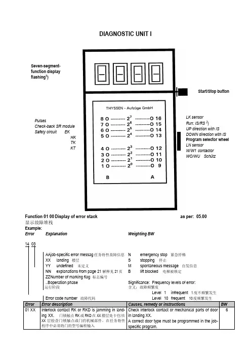
DIAGNOSTIC UNIT IFunction 01 00 Display of error stack as per: 05.00 显示故障堆栈Example:Error Explanation Weighting BW14 03AAjob-specific error messag任务特性故障信息N emergency stop 紧急停梯XX landing 楼层S stopping 停止YY undefined 未定义M spontaneous message 自发信息NN explanations from page 21 解释见21页 B lift blocked 电梯被锁定ZZ N umber of marking flag 标志编号..B o peration phase 运行阶段Significance: Frequency levels of error:含义:故障频繁度Level 1 infrequent 1度不频繁发生Error code number 故障代码Level 10 frequent 10度频繁发生Error Error description Causes, remedy or instructions BW01 XX Interlock contact RK or RKD is jamming in land-ing XX. 门锁触点RK或RKD在XX楼层处卡住/在XX层检查门锁触点或门的机械部件。
在任务特性程序中必须将门的型号编程输入Check interlock contact or mechanical parts of doorin landing XX.A correct door type must be programmed in the job-specific program.6Start/Stop buttonLK sensorRun: IS/RS2)UP direction with ISDOWN direction with ISProgram selector wheelLN sensorW/W1 contactorWO/WU SchützSeven-segment-function display flashing1)PulsesCheck-back SR module Safety circuit EKHKTKKT1) can be suppressed with switch 6S1 on circuit board MZ or with switch S5 on circuit board MZ1.1) Dependenton the function involved, reset can either mean emergency stop following by adjusting run or stopping of the lift installation2) Handshake is defined as cyclical data exchange (telegram) between two data carriers.1) SR module can be masked out via teach-in mode function AF 0d. Running-open operation and re-levelling with door open is not possible.1) Error from TCI work program 03.89/7 – no longer used.2) Error 35 00 and 3b 00 can no longer occur from work program 02.87/4 and error 36 00 can no longer occur from 06.95/25.1) SR module can be masked out through teach-in-mode function AF 0d. N Runnin-open operation and re-levelling with open door not possible.2) 0C 04 to 0C 0C leads also to stopping, if not provided otherwise in the lift-specific EPROM !1) If errors 65 00 to 74 00 occur more than 3 times, error 4F 00 will follow afterwards, which leads to spontaneous message and stopping1) DSP is the digital signal processor in the CPI controller2) Handshake is defined as cyclical data exchange (telegram) between two data carriers.04 NN TCI control – Interrogation of ZSE solenoid switchesNN is represented as a hexadecimal number; in the event of errors, it indicates the number of ZSE switches (no other than the ZSE switch of the car position may be actuated).04 00 applies to ZSE 25 to ZSE 3104 00 applies to ZSE 17 to ZSE 2404 00 applies to ZSE 9 to ZSE 1604 0C applies to ZSE 1 to ZSE 8Example: 0 4 0 CHexadecimal number 0C∣∣Binary number 0 0 0 0 1 1 0 0∣∣∣∣∣∣∣∣assigned ZSE switch 8 7 6 5 4 3 2 1The example shows that ZSE switches ZSE3 and ZSE4 (in 3. and 4. landing) have been activated.(Also compare hexadecimal code in part 4, page 2)04 NN TCM control – Interrogation of ZSE solenoid switchesIf ZSE switches are closed in the third and fourth landing, the TCM control will file two errors: 04 03und 04 0406 XX TCI control–Door locking not possible (from work program version 08.91/9)The lift will be put out of service for 15 min. after 3 unsuccessful door locking attempts. A new lockingattempt will be initiated after expiry of this period of time.XX = StandortDoor variant – hinged door:A new locking attempt will also be made within these 15 min. after opening of the landing door (TKopen) and closingit again (TK closed).Door variant D4 (with mechanical locking device)A start attempt will be enabled within 15 min., as soon as the control receives the bolt contact.06 XX TCM control–Door locking not possibleIf open bolt contact is recognized in the command chain preceding the position the following error willfollow14 XX (XX = bolt contact main side)18 XX (XX = bolt contact rear side)09 NN Car will be blocked in the landing >4 minExample 0 9 3 1Signal name (LED display on diagnostic unit I row A)0 KKD0 LSD1 KK O.K.1 LS O.K.0 TSUD0 TSOD0 TSU1 TSO activatedFor LEDs and signal names see Operating Instructions of Diagnostic Unit I, function 05 00, column0d (display of predefined memory locations, from page 25).19 NN Door zone not detectedExample1 VR1 A5A0 TO0 TU1 FL0 FS0 FO0 FUIn the operation phase STOP (lift at standstill), the CPU recognizes that the door zone calculatedfrom the landing vanes was left.For LEDs and signal names see Operating Instructions Diagnostic Unit I function 05 00, column 05(display of predefined memory locations,from page 25)1d NN Emergeny stop (wrong run direction)No run direction or both run directions were produced with the run contactor activated and the brakedisengaged.For LEDs and signal names see Operating Instructions, Diagnostic Unit I, function 05 00, column 05(display of predefined memory locations from page 25).In case of error 1d C8 the processor outputs the signals VR, A5A and FL (but without run directions);compare above representation of error 19 NN1E NN Deceleration not effectiveBinary display of car positionIt will be examined whether deceleration has been initiated already on reaching the marked terminallanding vanes.The position is indicated by the five bitst 20 to 25 as binary number.Example: 1 E 9 d0 27FO (run direction UP)1 26FU activated (run direction DOWN)0 251 241 23Position (hexadecimal number converted into1 22binary number)0 211 201 E 9d: bits 20 to 27 stand for landing 29, therefore only run direction UP exists, since 26 = 0 and 27 =1, and consequently 9 d will follow.Function 02 00 Display of order number (fromTCI work program version 06.88/6 and with TCM)显示定单号码(从TCI 06.88/6版工作程序起以及TCM梯)Example: Order No.: 27 70 06 42 10∣∣∣∣∣LED 5 12 3 10 1B A B A BFunction 03 00 Position indicator (decimal)楼层显示(十进制)Function 04 00 Operation phase1) Set function 05 00 with program selector wheel2) Press start-stop button3)Select desired column in 7-segment display with program selector wheelExample: Column 0d is desired. For example, select 0C 0d in 7-segment display, then left LED row B applies to column 0C and right LED row A applies to column 0d, etc.4) Interrogate LED display (compare overview and signal description)5) Exit: press start-stop button for longer than 2 s.The LEDs listed in the table will light on selecting the respective column (Col) :1) Error marking1) pulses are counted dependent on the run direction (20 to 27 is displayed in LED row A/B)1) will be displayed as hexadecimal number in LED row A. Example: 09 in LED row A LEDs 0000 1001 light up2)displays last failure before current failure cause column 2C. Is displayed in hexadecimal numbers as in column 2C1) MF3 (VA) stands for circuit board MF3 with double-sided insertion 1) MF3 (VA) stands for circuit board MF3 with double-sided insertion1) MF3 (VA) stands for circuit board MF3 with double-sided insertion1) not assigned currently.显示CPI。
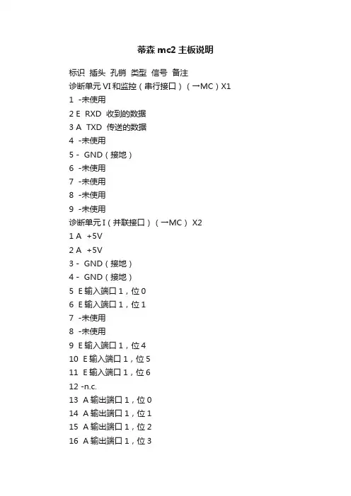
蒂森mc2主板说明标识插头孔销类型信号备注诊断单元VI和监控(串行接口)(→MC)X11 -未使用2 E RXD 收到的数据3 A TXD 传送的数据4 -未使用5 - GND(接地)6 -未使用7 -未使用8 -未使用9 -未使用诊断单元I(并联接口)(→MC) X21 A +5V2 A +5V3 - GND(接地)4 - GND(接地)5 E输入端口1,位06 E输入端口1,位17 -未使用8 -未使用9 E输入端口1,位410 E输入端口1,位511 E输入端口1,位612 -n.c.13 A输出端口1,位014 A输出端口1,位115 A输出端口1,位216 A输出端口1,位317 A输出端口1,位418 A输出端口1,位519 A输出端口1,位620 A输出端口1,位7本地总线(→MZ)X31 E/A CAN-H2 E/A CAN-L3 - GND(接地)群控总线(→MZ) X41 E/A CAN-H2 E/A CAN-L3 - GND(接地)驱动CPI(→MC) X51 -未使用2 -未使用3 A +24V4 A SWF5 E Channel A(槽道A) A脉冲6 E Channel B(槽道B) B脉冲7 - 0V8 E/A CAN-L 本地总线9 -未使用10 E STR11 A FO12 A +5V13 E Channel A(槽道A) *A脉冲14 E Channel B(槽道B) *B脉冲15 E/A CAN-H 本地总线旋转脉冲(减速的及液压的)(→MC) X6 1 A +24V2 A +12V3 E Pulses(脉冲)4 - GND(接地)额外串行接口MC(→MC) X71 A +24V2 E +12V (V)3 A Pulses(脉冲)4 - GND(接地)液压式驱动(→MZ,MC) X81 A +24V 输出I≤40mA2 A V2 备用输出1,X39:23 A V14 A FO FO←MC(V0)5 A FJR FJR←MZ(V)6 A FUR FUR←MZ(向下)7 A FOR FOR←MZ(向上)8 A FLR FLR←MZ(V2)9 A FSR FSR←MZ10 -平稳启动完成(启动)11 E STR STR(X5:10)12 - 0V平稳启动(→MC) X91 A SWF SWF←MC2 平稳启动完成电压供应5V X101 E +5V2 GND(接地)电压供应24V X111 E +24V2 GND(接地)额外串行接口MZ(→MZ) X121 A +5V2 E R×D(TTL)3 A T×D(TTL)4GND(接地)随行电缆(→MZ,MC,SR模块) X131 E ZS ZS-区域开关→SR模块2 A +24V 24V3 - 0V 0V4 E LK1 LK1-光幕选择器1→MC5 E LK LK-光幕选择器→MC6 E/A CAN-H 井道总线→MZ7 E/A CAN-L 井道总线→MZ井道总线主端(→MZ) X141 A INIH 初始化(站层号的编码)2 E/A CAN-H 井道总线3 E/A CAN-L 井道总线4 - GND(接地) GND(接地)井道总线后进口端(→MZ) X151 A INIH 初始化2 E/A CAN-H 井道总线→MS2等3 E/A CAN-L 井道总线→MS2等4 - GND(接地) GND(接地)附加作用的插头优选权(→MZ) X201 A +24V2 E V 优选权温度监控 X211 A +24V2 E V 温度监控过载(→MZ) X221 A +24V2 E ül过载启动抱闸(→MZ) X231 A =24V2 A VRB 抱闸磁铁启动1) 直接连接到平稳启动插头上。
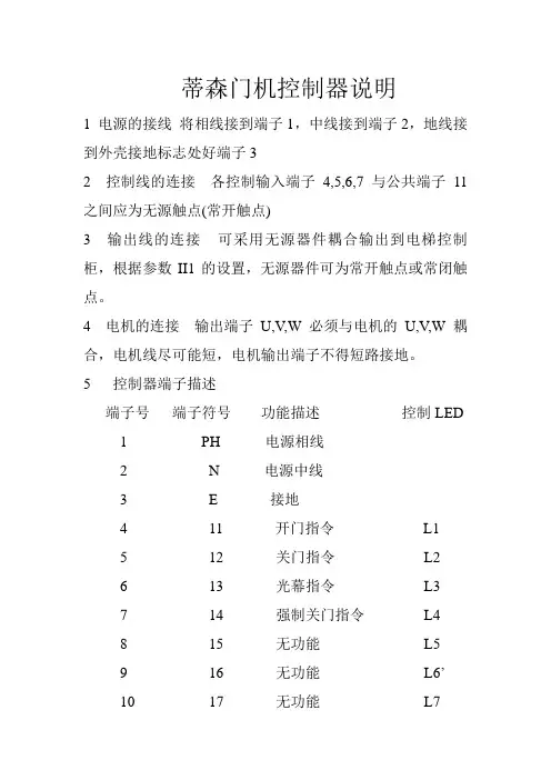
蒂森门机控制器说明1 电源的接线将相线接到端子1,中线接到端子2,地线接到外壳接地标志处好端子32 控制线的连接各控制输入端子4,5,6,7 与公共端子11之间应为无源触点(常开触点)3 输出线的连接可采用无源器件耦合输出到电梯控制柜,根据参数II1的设置,无源器件可为常开触点或常闭触点。
4 电机的连接输出端子U,V,W必须与电机的U,V,W耦合,电机线尽可能短,电机输出端子不得短路接地。
5 控制器端子描述端子号端子符号功能描述控制LED1 PH 电源相线2 N 电源中线3 E 接地4 11 开门指令L15 12 关门指令L26 13 光幕指令L37 14 强制关门指令L48 15 无功能L59 16 无功能L6’10 17 无功能L711 C 输入信号11到17的公共端12,13 继电器1 开门输出触点L9 14,15 继电器2 开门(重开门)输出触点L10 16,17 继电器3 门位置输出触点L11 18,19 继电器4 关门到位输出触点L1220 D 编码器A相脉冲输入L1521 TH 编码器B脉冲输入L1622 + 编码器电源电压+20V23 C 编码器电源接地GND3a Earth 编码器电缆屏蔽端24,25,26 U.V,W 电机接线端6 编码器接线指导黄色A相脉冲输出,绿色B相脉冲输出,棕色电源电压(DC20V)白色电源电压(0V)7控制器的调试与操作@检查总电源,检查现场电压是否符合门机控制器的电源要求(220V,50HZ)@将轿门定位到半开状态,用手将轿门拉到半开状态,以便接通电源盒输入指令后确定门的运行方向@接通电源,检查门运行方向,接通电源,屏幕显示“。
—”,按参数值+几次,注意轿门是否向关门方向移动。
如果轿门向关门方向移动,则说明电机接线正确。
如果轿门向开门方向移动,则必须交换两个相线来改变电机的转向。
@启动自学习运行,检查电机转向后可启动自学习运行,自学习方法:按下参数值+,直至门完全关闭,然后又完全打开,通过开门指令、门首先完全关闭,然后又完全打开。
版本:A 更改码:00 蒂森克虏伯电梯(上海)有限公司MF3-S 技术说明书TE036-SM生效日期:6/13/20061 概述参考MA12/6510/70 TCM Single-Board Lift Control MC2等相关文档;MF3为TCM-MC2系统中的轿厢控制板。
根据我工厂实际情况及市场实际需求,MF3-S 为在MF3的基础上,本地化设计的产品。
2 特性描述2.1 电源输入:典型使用 24VDC ;2.2 工作电压范围DC 9~40V;2.3使用功耗:不包括输入/输出,24VDC 电压输入时,小于等于50mA;3 功能描述3.1CAN BUS 通信:MF3-S 与TCM 主板(如MC2)进行实时的CAN BUS 串行通信,以交互轿厢控制与电梯控制主板(如TCM-MC2)之间的数据;3.2 内召按钮控制:MF3-S 已设计1-8层站的召唤按钮控制,如电梯高于8层站的情况,需MF4-S 板进行扩展;3.3 轿内显示控制:MF3-S 板解码来自主板的CAN BUS 数据包,再通过特定的数据接口,以向轿内显示板(如GMA9-S )提供正确的显示信息;3.4 轿内输入/输出信号:MF3-S 板上提供一些基本的输入信号,MF3-S 处理后发送给电梯控制主板,以如轿内基本操作信号:轿内优先、检修上/下、开关门到位等;同时MF3-S 也设计了一些基本的输出信号,MF3-S 通过CAN-BUS 接收控制主板信息,并正确输出,如超载运行、开/关门信号、上/下到站钟等等。
版本:A 更改码:00 蒂森克虏伯电梯(上海)有限公司MF3-S 技术说明书TE036-SM生效日期:6/13/20064 线路板安装及布局图版本:A 更改码:00 蒂森克虏伯电梯(上海)有限公司MF3-S 技术说明书TE036-SM生效日期:6/13/2006版本:A 更改码:00 蒂森克虏伯电梯(上海)有限公司MF3-S 技术说明书TE036-SM生效日期:6/13/20065 MF3-S 软件配置MF3-S 软件配置与MF3板完全兼容,即配用27C256存储芯片,工作程序根据最新释放版本,其中前后门由软件来定义,于我工厂电气车间进行烧录;版本:A 更改码:00 蒂森克虏伯电梯(上海)有限公司MF3-S 技术说明书TE036-SM生效日期:6/13/20066MF3-S 接口定义列表6.1接口类型中,表示方法:“I ”- 输入;“O ”-输出;“C ”- CAN BUS ;“M ”- 综合;“P ”- 电源信号功能信号名称端口定义接插件类型接口类型备注1-8层召唤按钮控制Car call button1-8层按钮输入0V +24 V1-8按钮灯输出X51:3-X58:3 X51:4-X58:4 X51:1-X58:1 X51:2-X58:2 CH2.54 × 4I轿内优先控制Preference V 0V +24V X34:3 X34:4 X34:1 CH2.54 × 4 I满载信号Occupied B 0V X15:1 X15:2 CH3.96 × 2 I 超载OverloadUB 0V X9:2 CH3.96 × 2 I开门按钮Door opening Button OT 0V +24V X59:3 X59:4 X60:1 CH2.54 × 4 I关门按钮Door closing buttonUT 0V +24V X60:3 X60:4 X60:1 CH2.54 × 4 I再平层传感器Re-leveling Sensor LN +24V 0V X42:2 X42:1 X42:3 CH3.96 × 3 I检修上/下Insp. op UP Insp, op DOWN IF IFO IFU 0V X40.1 X40.2 X40.3 CH3.96 × 3 I安全触板/光幕Articulated Light barrier d. KK 0V L T X5:1 X5:2 X5:3 CH3.96 × 3 I光电选层器Selector Sensor LK +24V 0V X2:2 X2:1 X2:3 CH3.96 × 3 I后门安全触板/光幕Articul. lever Rear Light barrierKKD 0V L TDX6:1 X6:2 X6:3CH3.96 × 3I版本:A 更改码:00 蒂森克虏伯电梯(上海)有限公司MF3-S 技术说明书TE036-SM生效日期:6/13/2006MF3-S 接口定义列表(续一)信号功能信号名称端口定义接插件类型接口类型备注根据工作程序指定的备用输入EBS10V ZTK X41:1 X41:2 X41:1 CH3.96 × 2 I前门开门到位Door open switch (Front)TSO 0V X3:1 X3:2 CH3.96 × 2 I后门开门到位Door open switch RearTSOD 0V X4:1 X4:2 CH3.96 × 2 I备用输入EES2 0V X47:1 X47:2 CH3.96 × 2 I召唤屏蔽使能Coding of calls AT 0V+24VX49;3 X49:4 X49:1 CH2.54 × 4I轿内显示板数据端Dataindicator MA/3TSData to MA X35M前门开/关门信号Door open/close .sig. (m.door)TU TO X43:1 X43:2 CH3.96 × 2 O后门开/关门信号Door open/cLose signal, rear side TUD TOD X45:1 X45:2 CH3.96 × 2 O前门强迫关门信号Nudging main side ZTZ +24V X44:2 X44:1 CH3.96 × 2 O 后门强迫关门信号Nudging rear side ZTZD + 24V X46:2 X46:1 CH3.96 × 2 O下到站钟输出Gong, BOTTOM I < 600 mA GU +24V X22:2 X22:1 CH3.96 × 2 O上到站钟输出Gong, top I < 600 mAGO + 24VX19:2 X19:1 CH3.96 × 2 O消防警示钟Fireman’s horn I < 600 mAFEH + 24V X21:2 X21:1CH3.96 × 2O版本:A 更改码:00 蒂森克虏伯电梯(上海)有限公司MF3-S 技术说明书TE036-SM生效日期:6/13/2006MF3-S 接口定义列表(续二)信号功能信号名称端口定义接插件类型接口类型备注紧急呼叫信号Call alarm I < 600 mA RW + 24V X20:2 X20:1 CH3.96 × 2 O备用3 RES3 I < 40 mA RES3X62:2 X62:1 CH3.96 × 2 O备用4 RES4 I < 40 mA RES4 +24VX63:2 X63:1 CH3.96 × 2OCAN BUS 总线CAN bus HIGH CAN bus LOW Front + rear coding CAN-H CAN-L 0V COD X64:4 X64:3 X64:2 X64:1 CH2.54 × 4C信号同X65CAN BUS 总线CAN bus HIGH CAN bus LOW Front + rear coding CAN-H CAN-L 0V CODX65:1 X65:2 X65:3 X65:4CH3.96 × 4C信号同X64电源电压Voltage supply Voltage supply+24V 0VX1:1X1: 2 CH3.96 × 2 P Voltage supply Command accept + 24V 0V X31:1 X31:2 CH3.96 × 2P。
DIAGNOSTIC UNIT IFunction 01 00 Display of error stack as per: 05.00 显示故障堆栈Example:Error Explanation Weighting BW14 03AAjob-specific error messag任务特性故障信息N emergency stop 紧急停梯XX landing 楼层S stopping 停止YY undefined 未定义M spontaneous message 自发信息NN explanations from page 21 解释见21页 B lift blocked 电梯被锁定ZZ N umber of marking flag 标志编号..B o peration phase 运行阶段Significance: Frequency levels of error:含义:故障频繁度Level 1 infrequent 1度不频繁发生Error code number 故障代码Level 10 frequent 10度频繁发生Error Error description Causes, remedy or instructions BW01 XX Interlock contact RK or RKD is jamming in land-ing XX. 门锁触点RK或RKD在XX楼层处卡住/在XX层检查门锁触点或门的机械部件。
在任务特性程序中必须将门的型号编程输入Check interlock contact or mechanical parts of doorin landing XX.A correct door type must be programmed in the job-specific program.6Start/Stop buttonLK sensorRun: IS/RS2)UP direction with ISDOWN direction with ISProgram selector wheelLN sensorW/W1 contactorWO/WU SchützSeven-segment-function display flashing1)PulsesCheck-back SR module Safety circuit EKHKTKKT1) can be suppressed with switch 6S1 on circuit board MZ or with switch S5 on circuit board MZ1.1) Dependenton the function involved, reset can either mean emergency stop following by adjusting run or stopping of the lift installation2) Handshake is defined as cyclical data exchange (telegram) between two data carriers.1) SR module can be masked out via teach-in mode function AF 0d. Running-open operation and re-levelling with door open is not possible.1) Error from TCI work program 03.89/7 – no longer used.2) Error 35 00 and 3b 00 can no longer occur from work program 02.87/4 and error 36 00 can no longer occur from 06.95/25.1) SR module can be masked out through teach-in-mode function AF 0d. N Runnin-open operation and re-levelling with open door not possible.2) 0C 04 to 0C 0C leads also to stopping, if not provided otherwise in the lift-specific EPROM !1) If errors 65 00 to 74 00 occur more than 3 times, error 4F 00 will follow afterwards, which leads to spontaneous message and stopping1) DSP is the digital signal processor in the CPI controller2) Handshake is defined as cyclical data exchange (telegram) between two data carriers.04 NN TCI control – Interrogation of ZSE solenoid switchesNN is represented as a hexadecimal number; in the event of errors, it indicates the number of ZSE switches (no other than the ZSE switch of the car position may be actuated).04 00 applies to ZSE 25 to ZSE 3104 00 applies to ZSE 17 to ZSE 2404 00 applies to ZSE 9 to ZSE 1604 0C applies to ZSE 1 to ZSE 8Example: 0 4 0 CHexadecimal number 0C∣∣Binary number 0 0 0 0 1 1 0 0∣∣∣∣∣∣∣∣assigned ZSE switch 8 7 6 5 4 3 2 1The example shows that ZSE switches ZSE3 and ZSE4 (in 3. and 4. landing) have been activated.(Also compare hexadecimal code in part 4, page 2)04 NN TCM control – Interrogation of ZSE solenoid switchesIf ZSE switches are closed in the third and fourth landing, the TCM control will file two errors: 04 03und 04 0406 XX TCI control–Door locking not possible (from work program version 08.91/9)The lift will be put out of service for 15 min. after 3 unsuccessful door locking attempts. A new lockingattempt will be initiated after expiry of this period of time.XX = StandortDoor variant – hinged door:A new locking attempt will also be made within these 15 min. after opening of the landing door (TKopen) and closingit again (TK closed).Door variant D4 (with mechanical locking device)A start attempt will be enabled within 15 min., as soon as the control receives the bolt contact.06 XX TCM control–Door locking not possibleIf open bolt contact is recognized in the command chain preceding the position the following error willfollow14 XX (XX = bolt contact main side)18 XX (XX = bolt contact rear side)09 NN Car will be blocked in the landing >4 minExample 0 9 3 1Signal name (LED display on diagnostic unit I row A)0 KKD0 LSD1 KK O.K.1 LS O.K.0 TSUD0 TSOD0 TSU1 TSO activatedFor LEDs and signal names see Operating Instructions of Diagnostic Unit I, function 05 00, column0d (display of predefined memory locations, from page 25).19 NN Door zone not detectedExample1 VR1 A5A0 TO0 TU1 FL0 FS0 FO0 FUIn the operation phase STOP (lift at standstill), the CPU recognizes that the door zone calculatedfrom the landing vanes was left.For LEDs and signal names see Operating Instructions Diagnostic Unit I function 05 00, column 05(display of predefined memory locations,from page 25)1d NN Emergeny stop (wrong run direction)No run direction or both run directions were produced with the run contactor activated and the brakedisengaged.For LEDs and signal names see Operating Instructions, Diagnostic Unit I, function 05 00, column 05(display of predefined memory locations from page 25).In case of error 1d C8 the processor outputs the signals VR, A5A and FL (but without run directions);compare above representation of error 19 NN1E NN Deceleration not effectiveBinary display of car positionIt will be examined whether deceleration has been initiated already on reaching the marked terminallanding vanes.The position is indicated by the five bitst 20 to 25 as binary number.Example: 1 E 9 d0 27FO (run direction UP)1 26FU activated (run direction DOWN)0 251 241 23Position (hexadecimal number converted into1 22binary number)0 211 201 E 9d: bits 20 to 27 stand for landing 29, therefore only run direction UP exists, since 26 = 0 and 27 =1, and consequently 9 d will follow.Function 02 00 Display of order number (fromTCI work program version 06.88/6 and with TCM)显示定单号码(从TCI 06.88/6版工作程序起以及TCM梯)Example: Order No.: 27 70 06 42 10∣∣∣∣∣LED 5 12 3 10 1B A B A BFunction 03 00 Position indicator (decimal)楼层显示(十进制)Function 04 00 Operation phase1) Set function 05 00 with program selector wheel2) Press start-stop button3)Select desired column in 7-segment display with program selector wheelExample: Column 0d is desired. For example, select 0C 0d in 7-segment display, then left LED row B applies to column 0C and right LED row A applies to column 0d, etc.4) Interrogate LED display (compare overview and signal description)5) Exit: press start-stop button for longer than 2 s.The LEDs listed in the table will light on selecting the respective column (Col) :1) Error marking1) pulses are counted dependent on the run direction (20 to 27 is displayed in LED row A/B)1) will be displayed as hexadecimal number in LED row A. Example: 09 in LED row A LEDs 0000 1001 light up2)displays last failure before current failure cause column 2C. Is displayed in hexadecimal numbers as in column 2C1) MF3 (VA) stands for circuit board MF3 with double-sided insertion 1) MF3 (VA) stands for circuit board MF3 with double-sided insertion1) MF3 (VA) stands for circuit board MF3 with double-sided insertion1) not assigned currently.显示CPI。
蒂森控制板操作器说明 YKK standardization office【 YKK5AB- YKK08- YKK2C- YKK18】DIAGNOSTIC UNIT IFunction 01 00 Display of error stackas per:显示故障堆栈 Example: Error Explanation Weighting BW14 03 任务特性故障信息 N emergency stop 紧急停梯 landing 楼层 S stopping 停止undefined 未定义 M spontaneous message 自发信息 explanations from page 21 解释见21B lift blocked 电梯被锁定Number of marking flag 标志编号operation phaseSignificance:Frequency levels of error:含义:故障频繁度Start/Stop buttonLK sensor Run: IS/RS 2)UP direction with IS DOWN direction with ISProgram selector wheelLN sensorW/W1 contactor WO/WU S chützSeven-segment-function display flashing 1)PulsesCheck-back SR moduleSafety circuit EK HKLevel 11) can be suppressed with switch 6S1 on circuit board MZ or with switch S5 on circuit board MZ1.1) Dependenton the function involved, reset can either mean emergency stop following by adjusting run or stopping of the lift installation2) Handshake is defined as cyclical data exchange (telegram) between two data carriers.1) SR module can be masked out via teach-in mode function AF 0d. Running-open operation and re-levelling with door open is not possible.1) Error from TCI work program 7 – no longer used.2) Error 35 00 and 3b 00 can no longer occur from work program 4 and error 36 00 can no longer occur from 25.1) SR module can be masked out through teach-in-mode function AF 0d. N Runnin-open operation and re-levelling with open door not possible.2) 0C 04 to 0C 0C leads also to stopping, if not provided otherwise in the lift-specific EPROM !1) If errors 65 00 to 74 00 occur more than 3 times, error 4F 00 will follow afterwards, which leads to spontaneous message and stopping1) DSP is the digital signal processor in the CPI controller2) Handshake is defined as cyclical data exchange (telegram) between two data carriers.Explanations of the existing error code numbers04 NN TCI control – Interrogation of ZSE solenoid switchesNN is represented as a hexadecimal number; in the event of errors, it indicates the number of ZSE switches (no other than the ZSE switch of the car position may be actuated).04 00 applies to ZSE 25 to ZSE 3104 00 applies to ZSE 17 to ZSE 2404 00 applies to ZSE 9 to ZSE 1604 0C applies to ZSE 1 to ZSE 8Example: 0 4 0 CHexadecimal number 0C??Binary number 00 0 0 1 1 0 0????????assigned ZSE switch8 7 6 5 4 3 2 1The example shows that ZSE switches ZSE3 and ZSE4 (in 3. and 4. landing) have been activated. (Alsocompare hexadecimal code in part 4, page 2)04 NN TCM control – Interrogation of ZSE solenoid switchesIf ZSE switches are closed in the third and fourth landing, the TCM control will file two errors: 04 03 und04 0406 XX TCI control–Door locking not possible (from work program version 9)The lift will be put out of service for 15 min. after 3 unsuccessful door locking attempts. A new lockingattempt will be initiated after expiry of this period of time.XX = StandortDoor variant – hinged door:A new locking attempt will also be made within these 15 min. after opening of the landing door (TK open)and closingit again (TK closed).Door variant D4 (with mechanical locking device)A start attempt will be enabled within 15 min., as soon as the control receives the bolt contact.06 XX TCM control–Door locking not possibleIf open bolt contact is recognized in the command chain preceding the position the following error willfollow14 XX (XX = bolt contact main side)18 XX (XX = bolt contact rear side)09 NN Car will be blocked in the landing >4 minExample 0 9 3 1LED Signal name (LED display on diagnostic unit I row A)KKDLSD1KK .1LS .TSUDTSODTSU1TSO activatedFor LEDs and signal names see Operating Instructions of Diagnostic Unit I, function 05 00, column 0d(display of predefined memory locations, from page 25).19 NN Door zone not detectedExample 1 9 C 81VR1A5ATOTU1FLFSFOFUIn the operation phase STOP (lift at standstill), the CPU recognizes that the door zone calculated from thelanding vanes was left.For LEDs and signal names see Operating Instructions Diagnostic Unit I function 05 00, column 05(display of predefined memory locations,from page 25)1d NN Emergeny stop (wrong run direction)No run direction or both run directions were produced with the run contactor activated and the brakedisengaged.For LEDs and signal names see Operating Instructions, Diagnostic Unit I, function 05 00, column 05(display of predefined memory locations from page 25).In case of error 1d C8 the processor outputs the signals VR, A5A and FL (but without run directions);compare above representation of error 19 NN1E NN Deceleration not effectiveBinary display of car positionIt will be examined whether deceleration has been initiated already on reaching the marked terminallanding vanes.The position is indicated by the five bitst 20 to 25 as binary number.Example: 1 E 9 d0 27FO (run direction UP)1 26FU activated (run direction DOWN)0 251 241 23Position (hexadecimal number converted into1 22binary number)0 211 201 E 9d: bits 20 to 27 stand for landing 29, therefore only run direction UP exists, since 26 = 0 and 27 = 1,and consequently 9 d will follow.Function 02 00 Display of order number (fromTCI work program version 6 and with TCM)显示定单号码(从TCI 6版工作程序起以及TCM梯)Example: Order No.: 27 7006 42 10?????LED 512 3 10 1B A B A BFunction 03 00 Position indicator (decimal)楼层显示(十进制)Function 04 00 Operation phaseFunction 05 00 Display of specified memory locations1) Set function 05 00 with program selector wheel2) Press start-stop button3)Select desired column in 7-segment display with program selector wheelExample: Column 0d is desired. For example, select 0C 0d in 7-segment display, then left LED row B applies to column 0C and right LED row A applies to column 0d, etc.4) Interrogate LED display (compare overview and signal description)5) Exit: press start-stop button for longer than 2 s.The LEDs listed in the table will light on selecting the respective column (Col) :Extension of columns for TCM control with MC1 or MC2 circuit boards1) Error marking1) pulses are counted dependent on the run direction (20 to 27 is displayed in LED row A/B)1) will be displayed as hexadecimal number in LED row A. Example: 09 in LED row A LEDs 0000 1001 light up2)displays last failure before current failure cause column 2C. Is displayed in hexadecimal numbers as in column 2C1) MF3 (VA) stands for circuit board MF3 with double-sided insertion1) MF3 (VA) stands for circuit board MF3 with double-sided insertion1) MF3 (VA) stands for circuit board MF3 with double-sided insertion1) not assigned currently.Function 07 00 Display of parameters of CPI controller (only with TCM controls) 显示CPI。
1 控制面板的操作1.1 概述控制面板操作必须由密码进入,防止被无关人员触动。
此密码在厂内预设定为 12343两行显示键区按下控制面板上的相应按钮可进入如下主菜单:(a)统计数据(b)故障记录(c)语言选择(d)参数设置每个主菜单又包括有多个子菜单。
每按“上翻”按钮一次,系统向前选定另一个主菜单或子菜单每按“下翻”按钮一次,系统向后选定另一个主菜单或子菜单按下“转换”按钮一次,退出主菜单或由子菜单退回到主菜单按下“送入”按钮一次,由主菜单进入子菜单,或者在子菜单中进行切换。
如果在5分钟内未有任何输入,显示器会自动切换到信息层;如果再过5分钟仍未有输入,则控制面板会黑屏,但是已经输入的数据会被保存,之后如果收到信的信息,控制面板会自动接通。
1.2 显示主菜单Enter Password1.3 统计菜单YESNO1.4 故障记录FXX =1.5 语言选择1.6 参数设置注:此通信参数用于DDU 与远程RS485通信。
1.6.1 设定时间和日期设定时间和日期(a)用 选择当前修改数值(b)用 键来增加或者减少数字值,数字范围:0~9(c) 按 键退出设置1.6.2设置通信的校验位设置通信的校验位YES(是)请使用无、奇、偶校验,此设置是基于485 ModbusYES 是请使用485 modbus者YES 是请使用RS 485 Modbus1.6.5设置服务密码设置服务密码用 键来选择数值范围内的四位数值1,2,3 和4.Save and exit Save and exit保存并退出保存并退出步骤说明:键入密码字12343按下(4)“送入” 键 确定所选Configuration(设置)出现在主菜单的上行显示原有的密码字密码设定的数位为5位,数字选择为1、2、3和4. 但是数字4不能用作密码的第一个数。
按(4)“送入” 键一次。
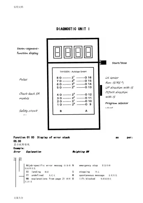
《LMS1电子板的教入操作》1. 作业前提:1). 适用于LMS1工作程序更换/升级后2). 新板的第一次运行2. 工具和器具的准备:1). Diagnostic unit I型诊断仪2). PDA和电脑不能进行LMS1调试3). 相当于轿厢额定标称载重量110%的标准砝码或重物3. LMS1电子板教入操作步骤:1). 准备——将电梯开到上端站的下一停站平层,并在确认轿厢内没有乘客后,将机房控制柜上的检修开关拨到“1”(检修状态)。
2). LMS1电子板教入——将Diagnostic unit I型诊断仪插入LMS1电子板,地址选择为1500(闪烁),按下Diagnostic unit I型诊断仪侧边的选择按钮,这时Diagnostic unit I型诊断仪显示持续为“15bF”,再次按选择按钮直到Diagnostic unit I型诊断仪显示“bFFF”。
a. 向上推动拨轮直到Diagnostic unit I型诊断仪显示表一中“显示”例所显示的地址,按下选择按钮后,会显示相应的数据,其含义请参照表一中右侧的“说明”例中的内容,再次按下Diagnostic unit I型诊断仪侧边的选择按钮,Diagnostic unit I型诊断仪将会显示表一中相应的“修改”例的地址。
如果不需要修改“说明”的参数,请继续向上或向下推动拨轮,将跳过相应的“修改”地址,显示下一个表一中“显示”例所显示的地址。
b. 如果需要修改其中参数,请按下Diagnostic unit I型诊断仪侧边的选择按钮并结合参照表一中右侧的“说明”例中的内容进行参数选择或修改后Diagnostic unit I型诊断仪将会自动显示完成提示“FEFE”,请按下Diagnostic unit I型诊断仪侧边的选择按钮,Diagnostic unit I型诊断仪将会自动显示下一行表一中“显示”例所显示的地址。
3). 所有参数检查/设定完成后,请向下拨动拨轮直到Diagnostic unit I型诊断仪显示退回到“bF00”或“bFFF”。
DIAGNOSTIC UNIT IFunction 01 00 Display of error stack as per:05.00显示故障堆栈 Example:ErrorExplanationWeighting BWlanding 楼层S stopping 停止undefined 未定义M spontaneous message 自发信息 explanations from page 21 解释21页B lift blocked 电梯被锁定 Number of marking flag 标志编Significance: Frequency levels of error:含义:故障频繁度Level 1 infrequent 1度不频繁11) Dependenton the function involved, reset can either mean emergency stop following by adjusting run or stopping of the lift installation2) Handshake is defined as cyclical data exchange (telegram) between two data carriers.1) SR module can be masked out via teach-in mode function AF 0d. Running-open operation and re-1) Error from TCI work program 03.89/7 – no longer used.2) Error 35 00 and 3b 00 can no longer occur from work program 02.87/4 and error 36 00 can no longer occur from 06.95/25.1) SR module can be masked out through teach-in-mode function AF 0d. N Runnin-open operation and21) If errors 65 00 to 74 00 occur more than 3 times, error 4F 00 will follow afterwards, which leads to1) DSP is the digital signal processor in the CPI controller2) Handshake is defined as cyclical data exchange (telegram) between two data carriers.Explanations of the existing error code numbers04 NN TCI control – Interrogation of ZSE solenoid switchesNN is represented as a hexadecimal number; in the event of errors, it indicates the number of ZSE switches (no other than the ZSE switch of the car position may be actuated).04 00 applies to ZSE 25 t o ZSE 3104 00 applies to ZSE 17 t o ZSE 2404 00 applies to ZSE 9 to ZSE 1604 0C applies to ZSE 1 to ZSE 8Example: 0 4 0 CHexadecimal number 0C∣∣Binary number 0 0 0 0 1 1 0 0∣∣∣∣∣∣∣∣assigned ZSE switch 8 7 6 5 4 3 2 1The example shows that ZSE switches ZSE3 and ZSE4 (in 3. and 4. landing) havebeen activated. (Also compare hexadecimal code in part 4, page 2)04 NN TCM control – Interrogation of ZSE solenoid switchesIf ZSE switches are closed in the third and fourth landing, the TCM controlwill file two errors: 04 03 und 04 0406 XX TCI control–Door locking not possible (from work program version 08.91/9)The lift will be put out of service for 15 min. after 3 unsuccessful doorlocking attempts. A new locking attempt will be initiated after expiry ofthis period of time.XX = StandortDoor variant – hinged door:A new locking attempt will also be made within these 15 min. after opening of the landing door (TK open) and closingit again (TK closed).Door variant D4 (with mechanical locking device)A start attempt will be enabled within 15 min., as soon as the control receives the bolt contact.06 XX TCM control – Door locking not possibleIf open bolt contact is recognized in the command chain preceding the position the following error will follow 14 XX (XX = bolt contact main side) 18 XX (XX = bolt contact rear side)09 NN Car will be blocked in the landing >4 minExample LED Signal name (LED display on diagnostic unit Irow A) 0 KKD 0 LSD 1 KK O.K. 1 LS O.K.0 TSUD 0 TSOD 0 TSU1 TSO activatedFor LEDs and signal names see Operating Instructions of Diagnostic Unit I, function 05 00, column 0d (display of predefined memory locations, from page 25).19 NN Door zone not detected0 TO0 TU1 FL0 FS0 FO0 FUIn the operation phase STOP (lift at standstill), the CPU recognizes that thedoor zone calculated from the landing vanes was left.For LEDs and signal names see Operating Instructions Diagnostic Unit Ifunction 05 00, column 05 (display of predefined memory locations,from page25)1d NN Emergeny stop (wrong run direction)No run direction or both run directions were produced with the run contactoractivated and the brake disengaged.For LEDs and signal names see Operating Instructions, Diagnostic Unit I,function 05 00, column 05 (display of predefined memory locations from page25).In case of error 1d C8 the processor outputs the signals VR, A5A and FL (butwithout run directions); compare above representation of error 19 NN1E NN Deceleration not effectiveBinary display of car positionIt will be examined whether deceleration has been initiated already onreaching the marked terminal landing vanes.The position is indicated by the five bitst 20 to 25 as binary number.0 211 201 E 9d: bits 20 to 27 stand for landing 29, therefore only run direction UPexists, since 26 = 0 and 27 = 1, and consequently 9 d will follow.Function 02 00 Display of order number (fromTCI work program version 06.88/6 and with TCM)显示定单号码(从TCI 06.88/6版工作程序起以及TCM梯)Example: Order No.: 27 70 06 42 10∣∣∣∣∣LED 5 12 3 10 1B A B A BFunction 03 00 Position indicator (decimal)楼层显示(十进制)Function 04 00 Operation phaseFunction 05 00 Display of specified memory locations1) Set function 05 00 with program selector wheel2) Press start-stop button3)Select desired column in 7-segment display with program selector wheelExample: Column 0d is desired. For example, select 0C 0d in 7-segment display, then left LED row B applies to column 0C and right LED row A applies to column0d, etc.4) Interrogate LED display (compare overview and signal description)5) Exit: press start-stop button for longer than 2 s.The LEDs listed in the table will light on selecting the respective column (Col) :Extension of columns for TCM control with MC1 or MC2 circuit boards1) Error marking1) pulses are counted dependent on the run direction (2071) will be displayed as hexadecimal number in LED row A. Example: 09 in LED row A LEDs2) displays last failure before current failure cause column 2C. Is displayed in hexadecimal1) MF3 (VA) stands for circuit board MF3 with double-sided insertion 1) MF3 (VA) stands for circuit board MF3 with double-sided insertion1。
TE014-SS 生效日期:2003-03-20 蒂森克虏伯电梯(上海)有限公司1前言1.1为进一步加强上海工厂的电梯配置管理、生产管理及质量管理,在本文中,就TIC-G1群控系统性能、功能等作比较详尽的说明,以及对群控系统的配置、部件号等方面作一些具体的规定。
1.2 TIC–G1群控系统采用“集中控制”、“外召发起”的群控技术,即由一个群控电脑主板,专门负责厅外召唤的信号登记和分配。
1.3 TIC–G1群控系统的调度原则,是基于外召唤发起的“最小等待时间”原则,其中充分考虑了电梯的“层楼距离”、“外召唤和指令的登记”情况、“超越情况”,以及“反向”情况等因素,实时分派具有最快响应时间可能性的电梯来应答每一个厅外召唤请求,从而充分挖掘电梯的运输能力,大大提高电梯的运行效率。
1.4 同时还具有“紧急供电运行”、“服务楼层设定”、以及“分散待梯”等运行功能,满足各种需求。
1.5 合同执行部门应根据本说明TE014-SS 生效日期:2003-03-20 蒂森克虏伯电梯(上海)有限公司2 TIC-G1群控系统的总体结构及性能指标2.1如图1所示,为TIC-G1群控系统总体结构框图TIC-G1总体结构框图2.2 对“每一组群控电梯”必须配一只群控柜,其中的主体是SM-GC电脑板。
SM-GC通过CAN-BUS 与各台控制柜电脑主板SM-01通信,从而调配群控内各台电梯投入有效的群控运行。
2.3 TIC-G1群控系统主要性能指标如下:2.3.1 TIC–G1群控系统的最大群控能力: 4台电梯群控;2.3.2各电梯的最大层站数:48层站;TE014-SS 生效日期:2003-03-20 蒂森克虏伯电梯(上海)有限公司2.3.3群控系统与各梯控制系统的通信方式:一对一的CAN BUS的串行通信;2.3.4后备运行:在群控电脑故障、维修或保养时,群控电脑的电源关断,各单梯可进行后备运行。
后备运行时,电梯的操作功能与单梯运行相同,一旦群控电脑恢复正常,电梯就立即自动转换成群控运行;2.3.5召唤重新分配:如果某一单梯主控电脑板失电,群控电脑就与该台电梯的召唤按钮直接通信,从而保证即使某台电梯主控电脑板失电,该台电梯的召唤按钮仍能继续在群控中发挥作用;2.3.6 切除怠慢电梯:如果系统发现某台电梯在收到分配到的召唤信号后,迟迟不关门运行,系统就会切除该台电梯,重新分配召唤,从而保证乘客不会有长时间的等待;2.3.7 直观的显示:群控电脑板上装有发光二极管显示,可通过它们直接监视群控电脑与单梯主控电脑之间的通信是否正常。