XT1511-RGBW全彩四合一灯珠规格书
- 格式:doc
- 大小:625.00 KB
- 文档页数:7
科锐xte 中文说明
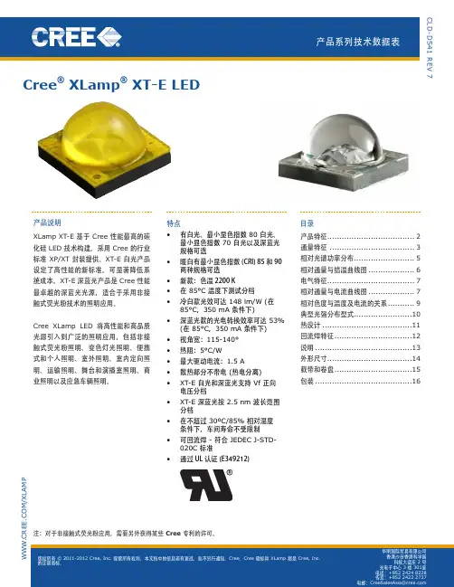
产品说明
X Lamp®X T-E采用Cree的行业标准XP/XT封装,是Cree性能最佳的以碳化硅为基底材料的LED技术。
X T-E白光LED设定了新的高性能标准,显著降低了系统成本。
X T-E宝蓝色LED是Cree性能最佳的宝蓝色光源,适用于非接触式荧光粉的应用。
Cree XL-amp LED为各类照明应用带来了卓越的照明性能与照明质量,这些应用包括非接触式荧光粉照明、变色照明、便携式照明和个人照明、室外照明、室内定向照明、运输照明、舞台照明、演播室照明、商业照明和应急车照明。
特点
·有白色、最低80-CRI白、最低
70-CRI白及宝蓝色等光色可选
·暖白色有最小显色指数85和90可
·新增特点:可以提供2200KCC
·在85°C时分档
·冷白光效最高达148 lm/W
(85°℃.350mA时)
·带墙上灯座的宝蓝色光效最高达5
(85°C、350mA时)
·视角:115-140°
·热阻:5C/W
·最大驱动电流:1.5A。
DATA SHEETIntroduction Performance Characteristics Mechanical Dimensions Characteristic Curves ReliabilityPacking Specification PrecautionP 2P 3P 5P 6P 9P 10P 11 CITILED COB SeriesStandard Type.Ra70 Min., Ra80 Min. Model CLU04Q-1212E11. Introduction1-1. Product Description1-2. Features・Mechanical Dimensions :28 × 28 × 1.4 (mm)・Package Structure :Aluminum Base Chip on Board ・Reference Assembly :M3 screw, Connector ・CRI (Ra):70 Min., 80 Min.・Nominal CCT :3,000K, 4,000K, 5,000K ( CRI(Ra) 70Min. )2,700K, 3,000K, 3,500K, 4,000K, 5,000K, 5,700K, 6,500K ( CRI(Ra) 80Min. )・Chromaticity Range:3-step Ellipse, the center refers to ANSI C78.377:2017. ( CRI(Ra) 70Min. )2-step Ellipse, the center refers to ANSI C78.377:2017. ( CRI(Ra) 80Min. )・Thermal Resistance :0.32C/W ・Maximum drive current :2760mA ・UL recognized component (E358566)・RoHS compliant・Better die arrangement for optics・Wide range of luminous flux and high efficacy・Improved lumen density compared with previous version CLU04Q -1212E1-303L7X4[1][2][3][4][5][1]:[2]:[3]:[4]:[5]:Nominal CCT CRI (Ra)Product NomenclatureCLU04Q 12123000K 70 Min.Product shape Die count in series Die count in parallel CITIZEN ELECTRONICS is the first COB manufacturer.With many years of knowledge, experience, and advanced packaging technology, we continue to produced high quality and highly reliable products.The new COB series, Version9, while keeping the conventional product lineup and package sizes, achieves both high color quality (2 Step ellipse) and higher driving capability.In addition, efficacy and reliability are improved by selecting superior materials and optimizing production processes.Our highly reliable and efficient COB light source contributes to the realization of a circular economy through energy saving and reduction of carbon emissions.2. Performance Characteristics2-1. Electro Optical Characteristics2-2. Absolute Maximum RatingsSymbol RatingPi 116.5*1If 2760*1Ir 1Top -40 ~ +100Tst -40 ~ +100Tc 120*2Tj140*3*2. Refer to 3. Outline drawing for Tc measurement point.*3. Junction temperature calculation formula : Tj = Tc + Rj-c × PiParameterInput Power (W)Forward Current (mA)Reverse Current (mA)Storage Temperature (C)Case Temperature (C)Junction Temperature (C)Operating Temperature (C)*1. Input power and forward current are the values when the LED is used within the range of the derating curve in this data sheet.( Tj=85C )Ra R9Tc25C*Min.Min.Min.Typ.Typ.Typ.Min.Typ.Max.CLU04Q-1212E1-303L7X43000K 70-5,6566,4286,9251761,08031.433.836.20.32CLU04Q-1212E1-403L7X44000K 70-5,6896,4656,9651771,08031.433.836.20.32CLU04Q-1212E1-503L7X45000K 70-5,7106,4896,9911781,08031.433.836.20.32CLU04Q-1212E1-272M2X22700K 8004,9915,6736,1111551,08031.433.836.20.32CLU04Q-1212E1-302M2X23000K 8005,1845,8926,3471611,08031.433.836.20.32CLU04Q-1212E1-352M2X23500K 8005,3036,0276,4931651,08031.433.836.20.32CLU04Q-1212E1-402M2X24000K 8005,4256,1666,6421691,08031.433.836.20.32CLU04Q-1212E1-502M2X25000K 8005,4096,1476,6231681,08031.433.836.20.32CLU04Q-1212E1-572M2X25700K 8005,3546,0856,5561671,08031.433.836.20.32CLU04Q-1212E1-652M2X26500K805,3046,0276,4941651,08031.433.836.20.32Notes :1. Citizen Electronics maintains a tolerance of ± 10% on luminous flux measurements.2. Citizen Electronics maintains a tolerance of ± 3% on forward voltage measurements.3. Citizen Electronics maintains a tolerance of ± 2 on Ra measurements. * : Values of Luminous flux at Tc=25C are provided as reference only.Product codeForward Current( mA )Thermal Resistance Rj-c ( C/W )CRI Nominal CCTLuminous flux( lm )Efficacy ( lm/W )Forward Voltage( V )Tj85C2,700K ( 0.4578, 0.4101)3,000K( 0.4339, 0.4033)3,500K ( 0.4078, 0.3930)4,000K ( 0.3818, 0.3797)5,000K ( 0.3446, 0.3551)5,700K ( 0.3287, 0.3425)6,500K( 0.3123, 0.3283)3-step Ellipse.2-step Ellipse.Color RegionNominal CCT Center Point ( x, y )---0.003540.00236-0.00507-0.001983-step 2-step 0.0083452.970.00634-0.00278 ( Rated current, Tj=85C )53.170.005560.004080.002720.00516-0.0027457.28Oval parameterMajor Axisa Minor Axisb E llipse Rotation Angleθ3-step 2-step * Color region stay within 3-step / 2-step ellipse from the chromaticity center.* The chromaticity center refers to ANSI C78.377:2017.* θ is the angle between the major axis of the ellipse and the x-axis, and a and b are the major and minor semi-axes of an ellipse.54.0059.6258.3859.460.009390.006260.004020.002680.00446-0.001900.008220.005482-3. Chromaticity CharacteristicsNote : Citizen Electronics maintains chromaticity ( x, y ) +/-0.0050.300.350.400.450.300.350.400.450.50yxx-y chart CIE19314,000K3,000KBlack Body Locus2,700K3,500K5,000K5,700K6,500K2-step 3-step3. Mechanical DimensionsUnit : mmTolerances unless otherwise specified : +/-0.3・Internal Circuit12 S 12 P Protection deviceLED deviceCathodeAnodeMarking 1 : Serial No.Marking 2 : Code No.CRI CCTDie count in parallel Die count in seriesCLU0xQ seriesMarking 3 : Data MatrixAN 12 12 ** ** *4. Characteristic Curves4-1. Forward Current Characteristics / Temperature CharacteristicsForward Current vs. Forward VoltageForward Current vs. Relative Luminous FluxTc=25CTc=25CCase Temperature vs. Forward VoltageCase Temperature vs. Relative Luminous FluxIf=1080mAIf=1080mA30.032.034.036.038.040.00100020003000V f [V ]If [mA]0%50%100%150%200%250%100020003000R e l a t i v e L u m i n o u s F l u x [a .u .]If [mA]32.033.034.035.036.0255075100125V f [V ]Tc [C]0%20%40%60%80%100%120%0255075100125R e l a t i v e L u m i n o u s F l u x [a .u .]Tc [C]4-2. Optical CharacteristicsTj=85CIf=1080mASpectrum : CRI(Ra) 80 Min.0%10%20%30%40%50%60%70%80%90%100%380430480530580630680730780R a d i a t i v e I n t e n s i t yWave length [nm]6,500K5,700K 5,000K 4,000K 3,500K 3,000K2,700KTj=85CIf=1080mASpectrum : CRI(Ra) 70 Min.0%10%20%30%40%50%60%70%80%90%100%380430480530580630680730780R a d i a t i v e I n t e n s i t yWave length [nm]5,000K4,000K3,000K4-2. Optical Characteristics (continued)4-3. Derating CharacteristicsRadiation Characteristic0%20%40%60%80%100%X Y80°70°60°50°40°30°20°10°-80°-70°-60°-50°-20°-30°-40°-10°90°-90°Case Temperaturevs. Allowable Forward Current1000200030000255075100125I f [m A ]Tc [C]5. Reliability5-1. Reliability Test5-2. Failure Criteria-40 C × 30 minutes – 100 C × 30 minutes, 100 cycle85 C, 85 %RH for 500 hoursThermal Shock TestContinuous Operation Test High Temperature Storage TestLow Temperature Storage Test Moisture-proof Test If=1080mA , Tj=140C (with Al-fin) ×1000hoursTest Item100 C × 1000 hours -40 C × 1000 hours Test ConditionIf=1080mA , Ta= 25C (with Al-fin) ×1000hours ( Tc=25C )U defines the upper limit of the specified characteristics. S defines the initial value.Note : Measurement shall be taken between 2 hours and 24 hours, and the test pieces should be return to the normal ambient conditions after the completion of each test.Total Luminous FluxΦvIf=1080mA<S × 0.85Measuring Item Symbol Measuring ConditionFailure CriteriaForward Voltage Vf If=1080mA >U × 1.1Unit : mmProduct : 30 pcs/tray1. TYPEe.g. CLU04Q-1212E12. P.No. ( Customer's P/N )3. Lot No.2175015(b)(a) Last two digit of the year 21 : Year 2021(b) Production month 7 : JulyNote: October, November and December are designated X,Y and Z.(c) CE's control number 4. Quantity(a)(c)Example of indication labele.g. 6. Packing Specification6-1. PackingAn empty tray is placed on top of a 6-tier tray which contain 30 pieces each.( Smallest packing unit : 180 pieces )A label with product name, quantity and lot number is placed on the upper empty tray.Tray ( Dimensions: 310 x 210 x 12 mm / Materials: Electrically conductive PS ) CUSTOMERTYPE P.NO Lot No Q'ty: CLU***-******-******* : ****** : ******* : ***--- ( 1 ) --- ( 2 ) --- ( 3 ) --- ( 4 )7. Precaution7-1. Handling with care for this product-Both the light emitting area and white rim around the light emitting area is composed of resin materials.Please avoid the resin area from being pressed, stressed, rubbed, come into contact with sharp metal nail(e.g. edge of reflector part) because the function, performance and reliability of this product are negatively impacted.-Please be aware that this product should not come into contact with any other parts while incorporating in your lightingapparatus or your other products.-Please be aware that careful handling is required after the attachment of lead wires to prevent the application of any loadto the connections.-For more information, please refer to application note "Instruction Manual(COB LED Package)".7-2. Countermeasure against static electricity-Handling of this product needs countermeasures against static electricity because this is a semiconductor product.-Please take adequate measures to prevent any static electricity being produced such as the wearing of a wristband oranti-static gloves when handling this product.-Every manufacturing facility in regard to the product (plant, equipment, machine, carrier machine and conveyance unit)should be connected to ground and please avoid the product to be electric-charged.-ESD sensitivity of this product is over 1000V (HBM, based on JEITA ED-4701/304).-After assembling the LEDs into your final product(s), it is recommended to check whether the assembled LEDs aredamaged by static electricity (electrical leak phenomenon) or not.-It is easy to find static damaged LED dies by a light-on test with the minimum current value.7-3. Caution of product assembly-Regarding this product assembling on the heat sink, it is recommended to use M3 screw.It might be good for screw tightening on the heat sink to do temporary tightening and final tightening.In addition, please don’t press with excess stress on the product.-The condition of the product assembling on the heat sink and the control of screw tightening torque needs to be optimized according to the specification of the heat sink.-Roughness, unevenness and burr of surface negatively impact thermal bonding between the product and heat sink andincrease heat thermal resistance between them.Confidence of thermally and mechanical coupling between the product and heat sink are confirmed by checkingthe mounting surface and measuring the case temperature of the product.-In order to reduce the thermal resistance at assembly, it might be good to use TIM (Thermal Interface Material) on whole contact surface of the product.In case of using thermal grease for the TIM, it might be good to apply uniformly on the contact surface of the product.In case of using thermal sheet for the TIM, it might be good to make sure that the product is NOT strained by stress when the screws are tightened for assembly.-For more information, please refer to application note "Instruction Manual(COB LED Package)".7-4. Thermal Design-The thermal design to draw heat away from the LED junction is most critical parameter for an LED illumination system. High operating temperatures at the LED junction adversely affect the performance of LED’s light output and lifetime. Therefore the LED junction temperature should not exceed the absolute maximum rating in LED illumination system. -The LED junction temperature while operation of LED illumination system depends upon thermal resistance of internal LED package (Rj-c), outer thermal resistances of LED package, power loss and ambient temperature. Please take both of the thermal design specifications and ambient temperature conditions into consideration for the setting of driving conditions.-For more information, please refer to application note "Thermal Management", "Instruction Manual(COB LED Package)".7-5. Driving Current-A constant current is recommended as an applying driving current to this product.In the case of constant voltage driving, please connect current-limiting resistor to each products in series and control the driving current to keep under the absolute maximum rating forward current value.-Electrical transient might apply excess voltage, excess current and reverse voltage to the product(s).They also affect negative impact on the product(s) therefore please make sure that no excess voltage, no excess current and no reverse voltage is applied to the product(s) when the LED driver is turn-on and/or turn-off.-For more information, please refer to application note "Driving", "Instruction Manual(COB LED Package)".7-6. Lighting at a minimum current value-A minimum current value of lighting of all dice is 15mA.When a minimum current is applied, LED dice may look different in their brightness due to the individual difference of the LED element, and it is not a failed product.7-7. Electrical Safety-This product is designed and produced according to IEC 62031:2008(IEC 62031:2008 LED modules for general lighting. Safety specification)-Dielectric voltage withstand test has been conducted on this product to see any failure after applyingvoltage between active pads and aluminum section of the product, and to pass at least 500V.-Considering conformity assessment for IEC62031:2008, almost all items of the specification depend uponyour final product of LED illumination system.Therefore, please confirm with your final product for electrical safety of your product.As well, the products comply with the criteria of IEC62031:2008 as single LED package.- A minimum current value of lighting of all dice is 60 mA. When a minimum current is applied, LED dice may look different in their brightness due tothe individual difference of the LED element, and it is not a failed product.7-8. Recommended soldering Condition (This product is not adaptable to reflow process.) -For manual solderingPlease use lead-free soldering.Soldering shall be implemented using a soldering bit at a temperature lower than 350C, and shall befinished within 3.5 seconds for one land.No external force shall be applied to resin part while soldering is implemented.Next process of soldering should be carried out after the product has return to ambient temperature.Contacts number of soldering bit should be within twice for each terminal.* Citizen Electronics cannot guarantee if usage exceeds these recommended conditions.Please use it after sufficient verification is carried out on your own risk if absolutely necessary.-For more information, please refer to application note "Instruction Manual(COB LED Package)".7-9. Eye Safety-The International Electrical Commission (IEC) published in 2006 IEC 62471”2006 Photobiological safety of lamps and lamp systems ” which includes LEDs within its scope.When sorting single LEDs according to IEC 62471, almost all white LEDs can be classifiedas belonging to either Exempt Group (no hazard) or Risk Group 1 (low risk).-However, Optical characteristics of LEDs such as radiant flux, spectrum and light distribution are factorsthat affect the risk group determination of the LED, and especially a high-power LED, that emits lightcontaining blue wavelengths,might have properties equivalent to those of Risk Group 2 (moderate risk).-Great care should be taken when directly viewing an LED that is driven at high current, has multipleuses as a module or when focusing the light with optical instruments, as these actions might greatlyincrease the hazard to your eyes.-It is recommended to regard the evaluation of stand-alone LED packages as a referenceand to evaluate your final product.7-10. This product is not designed for usage under the following conditions.If the product might be used under the following conditions, you shall evaluate its effect and appropriate them. In places where the product might:-directly and indirectly get wet due to rain and/or at place with the fear.-be damage by seawater and/or at place with the fear-be exposed to corrosive gas (such as Cl2, H2S, NH3, SOx, NOx and so on) and/or at place with the fear.-be exposed to dust, fluid or oil and/or at place with the fear.Precautions with regard to product use(1) This document is provided for reference purposes only so that CITIZEN ELECTRONICS' products are used as intended. CITIZEN ELECTRONICS neither makes warranties or representations with respect to the accuracy or completeness of the information contained in this document nor grants any license to any intellectual property rights or any other rights of CITIZEN ELECTRONICS or any third party with respect to the information in this document. Before purchasing or using any CITIZEN ELECTRONICS' products listed in this document, please confirm the latest product information with a CITIZEN ELECTRONICS‘s sales office, and formal specifications must be exchanged and signed by both parties prior to mass production.(2) All information included in this document such as product data, diagrams, charts, is current as of the date this document is issued.Such information, however, is subject to change without any prior notice.(3) CITIZEN ELECTRONICS has used reasonable care in compiling the information included in this document, but CITIZEN ELECTRONICS assumes no liability whatsoever for any damages incurred as a result of errors or omissions in the information included in this document.(4) Absent a written signed agreement, except as provided in the relevant terms and conditions of sale for product, and to the maximum extent allowable by law, CITIZEN ELECTRONICS assumes no liability whatsoever, including without limitation, indirect, consequential, special, or incidental damages or loss, including without limitation, loss of profits, loss of opportunities, business interruption and loss of data, and disclaims any and all express or implied warranties and conditions related to sale, use of product, or information, including warranties or conditions of merchantability, fitness for a particular purpose, accuracy of information, or no infringement.(5) Though CITIZEN ELECTRONICS works continually to improve products' quality and reliability, products can malfunction or fail. Customers are responsible for complying with safety standards and for providing adequate designs and safeguards to minimize risk and avoid situations in which a malfunction or failure of a product could cause loss of human life, bodily injury or damage to property, including data loss or corruption. In addition, customers are also responsible for determining the appropriateness of use of any information contained in this document such as application cases not only with evaluating by their own but also by the entire system. CITIZEN ELECTRONICS assumes no liability for customers' product design or applications.(6) The LEDs described in this brochure are intended to be used for ordinary electronic equipment (such as office equipment, communications equipment, measurement instruments and household appliances). Consult Citizen Electronics’s sales staff in advance for information on the applications in which exceptional quality and reliability are required, particularly when the failure or malfunction of the LEDs may directly jeopardize life or health ( such as for airplane, aerospace, submersible repeaters, nuclear reactor control system, automobiles, traffic control equipment, life support system and safety devices ) . This LED does not comply with ISO/TS 16949 (IATF16949) and is not intended for automotive applications.(7) The customer shall not reserve engineer by disassembling or analysis of the LEDs without having prior written consent from Citizen Electronics. When defective LEDs are found, the customer shall inform Citizen Electronics before disassembling or analysis.(8) When exporting our products, please ensure conformance with applicable laws and regulations and take appropriate actions such as obtaining an export license.(9) Please do not use or supply our products for any weapons of mass destruction (WMD) or for any other military purposes.(10) Please contact CITIZEN ELECTRONICS' sales office if you have any questions regarding the information contained in this document, or if you have any other inquiries.is a trademark or a registered trademark of CITIZEN ELECTRONICS CO., LTD. JAPAN. **********************.co.jp。
Quick Start GuideChroma-Q®Inspire XT™ Terminal Strip,Inspire™ Terminal Strip,Inspire Mini™ Terminal StripFor a full product manual please visit https://Part Number: CHINHLRGBWXT, CHINHLRGBWXTW,CHINHLRGBW32E, CHINHLRGBW42E, CHINHLRGBW65E, CHINHLW32E, CHINHLW42E, CHINHLW65E,CHINMINIHLRGBWT, CHINMINIHLRGBWTWModel: 632-8220, 632-8221,632-1500, 632-1600, 632-1700, 632-2500, 632-2600, 632-2700,632-6500, 632-6505Software Version (Engine) 2.21. OverviewThe Chroma-Q™ Inspire™ Terminal Strip LED house light features a single light engine with high powered LEDs (RGBW), a fully homogenized optic and controlled via the Inspire™ External Control Box. Through the Inspire External Control Box, the fixture can be controlled remotely through the ANSI E1.11 USITT DMX 512-A protocol.2. SafetyCaution 1. This product is for professional use only. It is NOT intended fordomestic or outdoor use.2. The bright flash of light during power-up and continuous strobe effect may cause epileptic seizure.3. This product must be used with safety cable.3. CablingFigure 1: Sample System DiagramFigure 2: Power & Data ConnectionsNote: The DMX cableconnected to the first Terminal Strip fixture from each Data Output of the External Control Box must be terminated with a 120Ω resistor. See Inspire Terminal Strip User Manual for details.Maximum DMX cable length from Data Out 1/2/3 to the 1st fixture must not exceed 500’/152m.Note:Refer to the marks on PCBLIVE NEUTRAL GROUNDP o w e r I n p u t : T e r m i n a l B l o c k H e a d e rData Plus Data MinusGround/ ShieldGround/ Shield Data Minus Data PlusData OutData InTo connect the wiring for power and control data:• The Power Input Connector Box (figure 3) is supplied with the fixture and is not attached. It must be mounted as described in the following stepsFigure 3: Power Connection: Connector BoxFigure 4: Power Connection: Light Fixture• Insert the power cable with the appropriate ½” NPT Connector or Cable Strain Reliefthrough the Connector Box (Figure 3). The hole on the connector box has a Suitable dimension to attach a ½” NPT connector on it. The Power Input Terminal Block Plug has three soft wires attached to it. Attach the provided wires to the wiring for the AC power input with Quick Connectors or Marret Connectors (Figure 3).• Put the Quick / Marret Connectors inside the Connector Box. Plug the wired Terminal Block Plug into the Power Input Terminal Block Header (Figure 4).• Connect the DMX control data cables from the Inspire External Control Box / another Inspire Light Fixture to the Terminal Block Plug. Ensure that the bare wire is not visible. Some insulation of the wire must be inside the hole. The maximum strip length is 4 mm (Figure 5). Plug Terminal Block Plug into the Terminal Block headers at the rear of the fixture (Figure 2 & 5).Strip Length 4mm MaxConnector Box ½” NPTConnector Quick ConnectorAC Power Input Cable POWER INPUT TERMINAL BLOCKPLUGConnector BoxPOWER INPUT TERMINAL BLOCK PLUGQuickConnectorFigure 6: Data Connection•Put the Connector Box in place and fasten the Connector Box with capacitive screw.Figure 7: Data In- First FixtureNotes:● IMPORTANT: Termination resistors (supplied with the External Control Box) are REQUIRED on first fixture in each data run (Figure 5) – see User Manuals for more details.● For DMX & data wires use Belden 9729 or CAT5e/6.● Max. cable distance from DATA OUT to first fixture must not exceed 152m/500 ft.● * Emergency Power is shown as an example only and may not be used on all projects.4. MountingA mounting bracket is built into the enclosure for overhead applications. Secure the fixture with a safety bond. A fixing hold is built into the enclosure. Optional accessories are also available for mounting Inspire light fixtures.5. OpticsThe Inspire XT is provided with a lens that delivers a beam angle of approximately 32°. Using a lens from the included Spread Lens kit will increase the beam to approximately 42° or 65°. For lens installation details, consult the instruction included with the kit.The Inspire Terminal Strip can be built with either Narrow, Medium or Wide lens. The beam angles are: Narrow: ~32°; Medium: ~42°; Wide: ~65°.The Inspire Mini Terminal Strip is built with wide lens with a beam angle of approximately ~65°.The Optional Spreader Lens Kit is available for changing the beam angle of any Inspire Light Fixture.6. ControlThe control functions are accessed through the Touch Screen display at the front panel of the Inspire External Control Box. The features of the Touch Screen Display are shown in Figure 8.Figure 8: Main screen of the External Control Box7. Further InformationPlease refer to the Chroma-Q Inspire TM manual for more detailed information. A copy of the manual can be found at the Chroma-Q website –https:///support/downloadsApprovals & DisclaimerThe information contained herein is offered in good faith and is believed to be accurate. However, because conditions and methods of use of our products are beyond our control, this information should not be used in substitution for customer's tests to ensure that Chroma-Q products are safe, effective, and fully satisfactory for the intended end use. Suggestions of use shall not be taken as inducements to infringe any patent. Chroma-Q sole warranty is that the product will meet the Chroma-Q sales specifications in effect at the time of shipment. Your exclusive remedy for breach of such warranty is limited to refund of purchase price or replacement of any product shown to be other than as warranted.Chroma-Q reserves the right to change or make alteration to devices and their functionality without notice due to on-going research and development.The Chroma-Q Space Force has been designed specifically for the lighting industry. Regular maintenance should be performed to ensure that the products perform well in the entertainment environment.If you experience any difficulties with any Chroma-Q products please contact your selling dealer. If your selling dealer is unable to help please contact ********************.Ifthesellingdealerisunabletosatisfyyourservicingneeds, please contact the following for full factory service:Outside North America: Tel: +44 (0)1494 446000 Fax: +44 (0)1494 461024 ********************North America:Tel: +1 416-255-9494 Fax: +1 416-255-3514 ********************For further information please visit the Chroma-Q website at https://chroma-com. Chroma-Q is a trademark, for more information on this visithttps:///trademarks.The rights and ownership of all trademarks are recognized.。
基础信息BASIC INFORMATIONAA -1产品特性03030506A -2光电参数及其它参数 A -3 产品结构尺寸及外观A -4配光角度及平均照度图 080811121214安装信息INSTALL INFORMATIONBB -1 产品示意图B -5 产品常见故障及排查方法B -6 申明及回收事宜B -2 产品、配件及所需工具示意图B -7 应用案例B -8 修订记录表0606A -5 工作长度及电参数关系表A -6 包装信息图表B -4 安装注意事项及其他1109B -3 产品连接示意图安装方式:3M 胶和螺丝固定安装。
适用于立体发光字、娱乐场所及酒店、商场装饰等方面。
用 途:产品特点:◇◇◇良好的衰减性能,芯片寿命长;◇◇◇采用XH -5Y 接头线,方便电源引入板间连接;柔软度佳,可适当弯曲;产品单组可剪,可纵向、横向任意剪切,不影响其他部分;可外接七彩控制器实现丰富的色彩变化效果;多种规格可选,也可根据客户需求定制;光电参数:备注:①.测试环境温度为 25±2℃;***④.如果选用不同档位的灯珠,色温(波长)会不同,光参数有一定的浮动。
UL 级联数量指的是,单端供电时的最大级联数量。
剪切位置,请见结构图示。
光通量、功率误差±10%。
②.以上数据为典型值,产品的实际参数可能会不同于典型数据,数据如有更改,恕不另行通知;③.以上光通量按照对应颜色点亮时,测试的参数;备注: 上述两图中的Rf 和Rg 值,均为对应灯珠情况下,实测所得TM-30数据:yx0.280.300.320.340.360.380.400.420.440.460.480.500.520.300.320.340.360.380.400.420.440.461931打靶图:产品尺寸:单位:mm[inch]产品示意图:②③④⑤⑥⑧⑨⑦⑩备注:如需具体尺寸,请联系销售人员索要。
端口说明:配光曲线:光强:cd C0/180,116.5C90/270,116.1平均光束角度(50%):116.3度有效平均照度:高度光束角:116.04备注: 上述两图,据H150-RGBW-TN4040+2835T-576-24-29S 测试所得,如需其它型号或色温的数据,请联系销售人员;工作长度及电参数关系表:H150-RGB+W-TN 4040+2835T-576-24单端供电时,产品数量(pcs )包装示意:123将检查OK 的产品或有配件袋的整齐摆放在台面上;将产品或配件袋整齐排列装入外箱中;将一张PCB 装入防静电气泡袋中,或两张背对背装入防静电气泡袋中;1. 本产品每2pcs 背靠背装一个防静电气泡袋;2. 上述包装数量和重量只针对图示包装方式,当为其它包装方式时包装数量和重量会存在差异,以上重量为预估重量具体以实物为准。
AnodeMarking 1Cathode(Tc Measurement Point)Marking 2Marking 1 : Serial No.Marking 2 : 12 05 27 M1YProduct 48pcs/tray3. Precautions for product assembly-When the LED package is attached to the heat sink by M3 screws, please be careful not to apply4. Insulation of the thermal section from the heat sink section of the LED has been confirmedup to 500V. However, for voltages higher than 500V, the customer should confirm the level of insulation Recommended installation screw pitch19.019.07. Lighting at a low currentA minimum current value of lighting of all dice is 25mA.When a minimum current is applied, LED dice may look different in their brightness due tothe individual difference of the LED element, and it is not a failed product.8. Please be aware that this product should not come into contact with any other partsin assembled status.9. Drive circuit- A constant current circuit is recommended as a drive circuit.And when two or more LED packages are connected, the series connectionbetween each package is recommended.- Please design a circuit that prevents any reverse voltage (excess current) from beingapplied to this product instantaneously when the circuit is ON or OFF.10. Heat generation- As this product is designed with consideration of the heat release property of module,a heat release design is required to use this product efficiently.Please ensure that heat generation is not in excess of the absolute maximum rating.(Refer to 4-1 Performance)- Factors responsible for an increase in temperature include heat generation attributed toambient temperature conditions or power dissipation. Thus, drive conditions should betaken into consideration, depending on ambient temperature (Ta).11. Recommended soldering condition (This product is not adaptable to reflow process)- Manual soldering- Soldering shall be implemented using a soldering bit of 40W or less with a temperature350°C or less within 3.5 seconds for one land.(Recommended condition in a case of lead-free solder condition)- No external force shall be applied to resin part during soldering.- Next process of soldering should be carried out after the product has returned to ambient temperature. - For soldering correction- Regarding soldering correction, above conditions shall be used.- Contacts number of soldering bit should be within twice for each terminal as a correction.* Citizen Electronics cannot guarantee if usage exceeds this recommended conditions.Please use it after sufficient verification is carried out on your own risk if necessary.Symbol CITILED12. Eye Safety- The International Electrical Commission (IEC) published in 2006 IEC 62471”2006 Photobiological safety oflamps and lamp systems” which includes LEDs within its scope.When sorting single LEDs according to IEC 62471, most white LEDs can be classified as belonging toeither Exempt Group or Risk Group 1.- However, Optical characteristics of LEDs such as radiant flux, spectrum and light distribution are factors that affect the risk group determination of the LED, and especially a high-power LED,that emits light containing blue wavelengths, may have properties equivalent to those of Risk Group 2.- Great care should be taken when directly viewing an LED that is driven at high current,has multiple uses as a module or when focusing the light with optical instruments,as these actions may greatly increase the hazard to your eyes.- It is recommended to regard the evaluation of stand-alone LED packages as a reference and to evaluate the customer's final product.13. The use of Class 2 power supply is assumed for this product.14. If the product might to be used under the following conditions, the customer must evaluateits approproateness them. This product is not designed for use under the following conditions.in places where the product might:- get wet due to rain- suffer from damage caused by salt.- be exposed to corrosive gas such as Cl, H2S, NH3, SO2, Nox and so on.- be exposed to dust, fluid or oil.Symbol CITILEDDATA SHEET11/11 9. Precautions with regard to product use1. This document is provided for reference purposes only so that CITIZEN ELECTRONICS'products are used as intended. CITIZEN ELECTRONICS neither makes warranties orrepresentations with respect to the accuracy or completeness of the information containedin this document nor grants any license to any intellectual property rights or any otherrights of CITIZEN ELECTRONICS or any third party with respect to the informationin this document.2. All information included in this document such as product data, diagrams, charts,is current as of the date this document is issued.Such information, however, is subject to change without any prior notice.Before purchasing or using any CITIZEN ELECTRONICS' products listed in this document,please confirm the latest product information with a CITIZEN ELECTRONICS' sales office,and formal specifications must be exchanged and signed by both parties prior to mass production.3. CITIZEN ELECTRONICS has used reasonable care in compiling the informationincluded in this document,but CITIZEN ELECTRONICS assumes no liability whatsoever for any damages incurred asa result of errors or omissions in the information included in this document.4. Absent a written signed agreement, except as provided in the relevant terms and conditions ofsale for product, and to the maximum extent allowable by law, CITIZEN ELECTRONICSassumes no liability whatsoever, including without limitation, indirect, consequential, special,or incidental damages or loss, including without limitation, loss of profits, loss of opportunities,business interruption and loss of data, and disclaims any and all express or implied warrantiesand conditions related to sale, use of product, or information, including warrantiesor conditions of merchantability, fitness for a particular purpose, accuracy of information,or no infringement.5. Though CITIZEN ELECTRONICS works continually to improve products' quality and reliability,products can malfunction or fail. Customers are responsible for complying with safety standardsand for providing adequate designs and safeguards to minimize risk and avoid situationsin which a malfunction or failure of a product could cause loss of human life,bodily injury or damage to property, including data loss or corruption.In addition, customers are also responsible for determining the appropriateness ofuse of any information contained in this document such as application cases not only withevaluating by their own but also by the entire system.CITIZEN ELECTRONICS assumes no liability for customers' product design or applications.6. Please contact CITIZEN ELECTRONICS' sales office if you have any questions regardingthe information contained in this document, or if you have any other inquiries.CITIZEN Micro HumanTech is a registered trademark of Citizen Holding Co., Japan.CITILED is a registered trademark of CITIZEN ELECTRONICS CO., LTD. JapanSymbol CITILEDName CLL030-1205A1-273M1A2CITIZEN ELECTRONICS CO.,LTD. JAPANRef.CE-P1527 10/11。
2025led灯珠规格书【原创实用版】目录1.2025LED 灯珠概述2.规格参数3.应用领域4.发展前景正文【2025LED 灯珠概述】2025LED 灯珠,即直径为 2.5 毫米的 LED 灯珠,是一种采用半导体材料制作的高效节能照明产品。
相较于传统的照明设备,2025LED 灯珠具有更高的光效、更低的能耗、更长的寿命以及更小的体积等优点,因此在照明市场具有广泛的应用前景。
【规格参数】2025LED 灯珠的规格参数主要包括以下几个方面:1.尺寸:直径为2.5 毫米,长度为 1.2 毫米。
2.光效:光效是指 LED 灯珠发出的光功率与消耗的电功率之比,单位为流明/瓦特(lm/W)。
2025LED 灯珠的光效一般在 100-150lm/W 之间,部分产品甚至可达到 200lm/W 以上。
3.色温:色温是指光源所发出的光的颜色,用单位“开尔文(K)”表示。
2025LED 灯珠的色温范围较广,一般可分为暖白光(2700-3200K)、中性白光(3500-4500K)和冷白光(4500-6500K)三类。
4.显色指数:显色指数是指 LED 灯珠对物体颜色的还原能力,用单位“拉(Ra)”表示。
2025LED 灯珠的显色指数一般在 70-90Ra 之间,部分产品甚至可达到 90Ra 以上。
5.寿命:寿命是指 LED 灯珠在正常工作条件下能够保持正常发光的时长,一般以小时为单位。
2025LED 灯珠的寿命一般在 5 万小时以上,部分产品甚至可达到 10 万小时以上。
【应用领域】2025LED 灯珠凭借其优异的性能,广泛应用于以下几个领域:1.家庭照明:如台灯、吸顶灯、球泡灯等。
2.商业照明:如店铺、办公室、酒店等场所的照明。
3.交通照明:如道路、隧道、停车场等场所的照明。
4.景观照明:如城市景观、公园、广场等场所的照明。
5.植物生长照明:适用于蔬菜、水果、花卉等植物的生长周期,可提高产量和品质。
【发展前景】随着全球环保意识的提高和节能减排的需求,LED 照明产业得到了快速发展。
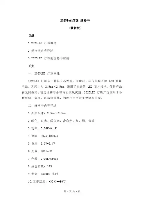
2025led灯珠规格书(最新版)目录1.2025LED 灯珠概述2.规格书内容详述3.2025LED 灯珠的优势与应用正文一、2025LED 灯珠概述2025LED 灯珠是一款具有高性能、低能耗、环保等特点的 LED 灯珠产品。
其尺寸为 2.5mm×2.5mm,采用了先进的 LED 芯片技术,使得产品在光照效果、稳定性和寿命等方面表现优越。
2025LED 灯珠广泛应用于各种照明、装饰、显示等领域,为现代生活带来便捷与美观。
二、规格书内容详述1.外形尺寸:2.5mm×2.5mm2.颜色:白光、暖白光、冷白光、红、绿、蓝等3.功率:0.06W-0.1W4.电流:20mA-1000mA5.电压:3.0V-3.4V6.光效:>80lm/W7.色温:2700K-6500K8.显色指数:>759.寿命:>50000 小时10.工作温度:-30℃-+60℃11.储存温度:-40℃-+80℃12.抗震性能:1000 次三、2025LED 灯珠的优势与应用1.节能环保:2025LED 灯珠具有低能耗特点,较传统照明产品节能 60% 以上,有助于减少碳排放,保护环境。
2.长寿命:2025LED 灯珠寿命长达 50000 小时,是传统照明产品的数倍,大大降低了维护成本。
3.良好的光照效果:2025LED 灯珠光效高,显色指数优良,能提供舒适、自然的光线环境。
4.广泛的应用领域:2025LED 灯珠可用于各类照明产品,如台灯、吸顶灯、筒灯等;以及显示屏、交通信号灯、车灯等特殊应用领域。
总之,2025LED 灯珠凭借其优异的性能和环保特点,已成为照明市场的主流产品。
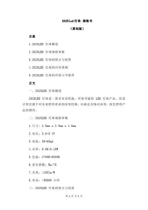
2025led灯珠规格书(原创版)目录1.2025LED 灯珠概述2.2025LED 灯珠规格参数3.2025LED 灯珠的特点与优势4.2025LED 灯珠的应用领域5.2025LED 灯珠的环保与节能性正文一、2025LED 灯珠概述2025LED 灯珠是一款具有高性能、环保节能的 LED 灯珠产品,其设计理念源于对未来照明需求的深度挖掘,以满足市场对高效、绿色照明产品的期待。
二、2025LED 灯珠规格参数1.尺寸:2.0mm x 2.5mm x 1.0mm2.电压:3.0-3.4V3.电流:30-60mA4.功率:0.06-0.18W5.色温:2700K-6500K6.显色指数:Ra>757.光效:>150lm/W8.寿命:>50000 小时三、2025LED 灯珠的特点与优势1.高亮度:2025LED 灯珠具有高光效,能提供充足的光线,满足照明需求。
2.宽色温范围:可根据不同场景和需求选择合适的色温,满足多样化照明需求。
3.高显色指数:Ra>75,能真实还原物体颜色,提供舒适视觉体验。
4.长寿命:使用寿命长达 50000 小时,降低了维护成本。
5.节能环保:低功耗设计,节约能源,减少碳排放。
四、2025LED 灯珠的应用领域1.家庭照明:适用于台灯、吸顶灯、吊灯等各类家居照明产品。
2.商业照明:适合用于办公室、餐厅、酒店等商业场所的照明。
3.工业照明:可应用于工厂、仓库等场所的照明,提高工作效率。
4.景观照明:适用于城市景观、公园、广场等户外照明场合。
五、2025LED 灯珠的环保与节能性2025LED 灯珠的节能性能表现在其低功耗设计,相较于传统照明产品,能节约大量能源。
同时,其环保特性体现在长寿命、无汞、无紫外线辐射等方面,减少了对环境的污染。
1.目的Purpose:内置IC-LED系列LED灯头表面使用的是高硬度的硅树脂,能够确保客户使用环氧树脂,PU胶,硅胶滴胶加工时都不会死灯,也有非常好的抗硫化能力。
和支架的兼容性也非常好,但是硅树脂对湿度和除湿处理要求非常高,在潮湿季节使用时需要非常注意,确保生产的安全性。
2.运输及适用范围:所有内置IC-LED系列产品在运输过程中,需保持正面朝上,防潮防水,运输过程中逼免挤压、碰撞和剧烈震动。
3.产品储存及期限:室温密封存储:20℃~30℃,40%~60%RH,产品有效期为3个月;防潮密封存储:20℃~30℃,25%~60%RH,产品有效期为6个月;产品拆包开封后,建议1 小时内使用完成,(环境条件温度<30℃,湿度<60%)。
4.除湿处理LED 产品超出以上规定期限,或者由于其他原因受潮,建议客户做除湿处理后再使用。
除湿方法:70℃-75℃/22±2 小时。
5.静电防护LED 是静电敏感器件,虽然LED 产品具有优异的抗静电能力,但每经历一次静电释放产生的冲击,都会对LED 造成一定程度的损坏。
因而在使用LED 产品过程中需要做好静电防护措施,例如佩戴防静电手套及防静电手环等。
6.手动焊接操作指引建议使用功率不超过30W 的电烙铁,控制电烙铁温度不高于380℃,每次焊接时电烙铁在支架引脚上停留时间不超过3秒,如需要反复焊接时,间隔停留时间不少于2秒,避免长时间高温对L ED 造成损伤。
焊接过程中,请勿触摸或挤压LED 的表面,避免对L ED 内部造成损伤,同时请注意避免电烙铁对LED 表面胶体的烫伤及其它损伤。
7.回流焊指引回流焊相关参数设定,请参考下图及下表,推荐使用千住、阿尔法、汉高乐泰等品牌焊锡膏,建议客户根据所采用的焊锡材料供应商提供的材料特性基础上进行必要的调整。
8.生产注意事项1. 所有产品,在贴片时,请仔细检查,若真空包装完好无损,无漏气现象,请直接使用,可以不用烘烤除湿处理。
2016闪光灯珠规格书摘要:1.2016 闪光灯珠规格书概述2.主要参数3.产品特点4.应用领域5.安装与使用注意事项正文:【2016 闪光灯珠规格书概述】2016 闪光灯珠规格书主要介绍了一款高性能的闪光灯珠产品。
该产品凭借其出色的性能和稳定的可靠性,广泛应用于各种照明和拍摄场景中。
本文将对该产品的主要参数、特点、应用领域以及安装与使用注意事项进行详细阐述。
【主要参数】2016 闪光灯珠的主要参数如下:1.尺寸:φ3-φ100mm2.颜色:红、绿、蓝、黄、白、紫等3.亮度:5000-100000mcd4.工作电压:3.0-3.4V5.工作电流:50-1000mA6.视角:5°-120°7.发射距离:500-1000 米【产品特点】2016 闪光灯珠具有以下特点:1.高亮度:采用高亮度LED 芯片,亮度高达100000mcd,能够在黑暗环境下提供出色的照明效果。
2.丰富的颜色:支持红、绿、蓝、黄、白、紫等多种颜色,满足不同场合的拍摄需求。
3.良好的散热性能:采用铝合金散热器,保证产品在长时间工作过程中不会过热。
4.宽视角:视角可调范围达到5°-120°,满足不同拍摄角度的需求。
5.稳定的可靠性:采用优质的电子元件和严格的生产工艺,确保产品在各种工况下的稳定可靠性。
【应用领域】2016 闪光灯珠广泛应用于以下领域:1.摄影摄像:用于拍摄照片和视频,提供丰富的光线效果。
2.舞台灯光:用于舞台表演、演唱会等场合,营造激情四溢的氛围。
3.户外照明:用于户外活动、探险等场合,提供可靠的照明保障。
4.广告宣传:用于广告拍摄、产品展示等场合,提升宣传效果。
【安装与使用注意事项】1.在安装时,请确保产品与电源电压、电流匹配,避免电压不稳定导致的损坏。
2.使用过程中,请不要让产品浸泡在水中或暴露在潮湿环境中,以免影响产品性能。
3.不要在高温环境中使用,以免损坏产品。
4.长时间不使用时,请将产品存放在阴凉、干燥的地方。
ProLight PBED-15FTE-S 15W Power LED Technical Datasheet Version: 1.0Features‧Compact light source‧R, G, B, W four color in one package ‧Lead free reflow soldering‧Superior ESD protection‧RoHS compliant Main Applications‧Entertainment lighting (Stage lighting)‧Architectural lighting‧Mood lighting‧Outdoor lighting‧Indoor lightingIntroduction‧ProLight PBED colorful series is a color changeable LED with maximum 4 colorchips in one package. Compared to discrete LEDs, PBED series reduce thedistance between LED die, creating a small optical source for excellent opticalcontrol and efficient color mixing. ProLight PBED series is much suitable for theapplication of color-changing lighting, especially for entertainment lighting.2019/02No. 89, Xiyuan Rd., Zhongli City, Taoyuan County 320,No. 89, Xiyuan Rd., Zhongli City, Taoyuan County 320, ::::2Notes:1. Drawing not to scale.2. All dimensions are in millimeters.3. Unless otherwise indicated, tolerances are ±0.15mm.4. Please do not solder the emitter by manual hand soldering, otherwise it will damage the emitter.5. Please do not use a force of over 1kgf impact or pressure on the lens of the LED, otherwise it will cause a catastrophic failure.*The appearance and specifications of the product may be modified for improvement without notice.Emitter Mechanical DimensionsNo. 89, Xiyuan Rd., Zhongli City, Taoyuan County 320, Thermal Forward Voltage V F (V)Forward Voltage V F (V)Resistance @700mARefer @1000mAJunction to Color Min.Typ.Max.Typ.Slug (°C/ W)Red 2.10 2.40 2.90 2.67 1.8Green 2.90 3.60 4.20 3.77Blue 2.80 3.10 3.60 3.21White2.803.103.603.21●ProLight maintains a tolerance of ±0.1V for Voltage measurements.Luminous Flux or Radiometric PowerPart Number @700mA Refer @1000mAColor EmitterMinimum Typical Typical Red PBED-15FTE-S57 lm 70 lm 94 lm Green 140 lm 160 lm 200 lm Blue 800 mW 870 mW 1650 mW White175 lm225 lm298 lm●Do not use below 40mA.●ProLight maintains a tolerance of ±7% on flux and power measurements.●Please do not drive at rated current more than 1 second without proper heat sink.3Flux Characteristics, T J = 25°CElectrical Characteristics, T J = 25°COptical Characteristics at 700mA, T J = 25°CTotal included Viewing Dominant Wavelength λD , Angle Angle Radiation Color or Color Temperature CCT (degrees)(degrees)PatternMin.Typ.Max.θ0.90V2 θ1/2LambertianRed 623 nm 626 nm 633 nm 160120Green 521 nm 527 nm 533 nm 160120Blue 453 nm 456 nm 458 nm 160120White5760 K6500 K7250 K160120●ProLight maintains a tolerance of ±1nm for dominant wavelength measurements.●ProLight maintains a tolerance of ±5% for CCT measurements.Absolute Maximum RatingsParameter Red/Green/Blue/WhiteDC Forward Current40 -1000 mAPeak Pulsed Forward Current (mA)1500 (less than 1/10 duty cycle@1KHz) ESD Sensitivity±4000V (Class III)(HBM per MIL-STD-883E Method 3015.7)LED Junction Temperature135°COperating Board Temperature-40°C -85°CStorage Temperature-40°C -85°CSoldering Temperature JEDEC 020c 260°C Allowable Reflow Cycles3Reverse Voltage Not designed to be driven in reverse bias Photometric Luminous Flux Bin Structure at 700mAColor Bin CodeMinimum Maximum Photometric Flux (lm)Photometric Flux (lm)Red A5768 B6882Green A140165 B165195White A175210 B210255●ProLight maintains a tolerance of ±7% on flux and power measurements.●The flux bin of the product may be modified for improvement without notice.Color Bin CodeMinimum Maximum Radiometric Power (mW)Radiometric Power (mW)Blue A800900 B9001050●ProLight maintains a tolerance of ±7% on flux and power measurements.●The flux bin of the product may be modified for improvement without notice.Radiometric Power Bin Structure at 700mANo. 89, Xiyuan Rd., Zhongli City, Taoyuan County 320,4No. 89, Xiyuan Rd., Zhongli City, Taoyuan County 320, 0.280.300.320.340.360.380.260.280.300.320.340.36yxPlanckian (BBL)CQ17250 K6860 K6070 K5760 KCQ26230 K6570 K5Color BinWhite Binning Structure Graphical RepresentationWhite Bin Structure Bin Codex y Typ. CCT (K)Bin Codex y Typ. CCT (K)CQ10.3190 0.3507 6150CQ20.3105 0.3343 67500.3267 0.3370 0.3187 0.3207 0.3187 0.3207 0.3107 0.3043 0.31050.33430.30200.3178●Tolerance on each color bin (x , y) is ±0.005Color Bin Code Minimum Dominant Maximum Dominant Wavelength (nm)Wavelength (nm)Red4623633Green 1521527 2527533Blue6453458●ProLight maintains a tolerance of ±1nm for dominant wavelength measurements.Note: Although several bins are outlined, product availability in a particular bin varies by production run and by product performance. Not all bins are available in all colors.Dominant Wavelength Bin Structure6No. 89, Xiyuan Rd., Zhongli City, Taoyuan County 320,No. 89, Xiyuan Rd., Zhongli City, Taoyuan County 320, 70.00.20.40.60.81.0350400450500550600650700750800850R e l a t i v e S p e c t r a l P o w e r D i s t r i b u t i o nWavelength (nm)Color Spectrum, T J = 25°C2. WhiteStandard Eye Response CurveWhite1. Blue 、Green 、Red0.00.20.40.60.81.0400450500550600650700R e l a t i v e S p e c t r a l P o w e r D i s t r i b u t i o nWavelength (nm)BlueGreen RedNo. 89, Xiyuan Rd., Zhongli City, Taoyuan County 320,81. Forward Voltage vs. Forward Current 0200400600800100012001.41.82.22.63.03.4A v e r a g e F o r w a r d C u r r e n t (m A )Forward Voltage (V)Red400200400600800100012002.02.42.83.23.64.0A v e r a g e F o r w a r d C u r r e n t (m A )Forward Voltage (V)40White0200400600800100012002.02.42.83.23.64.0A v e r a g e F o r w a r d C u r r e n t (m A )Forward Voltage (V)40Green0200400600800100012002.02.42.83.23.64.0A v e r a g e F o r w a r d C u r r e n t (m A )Forward Voltage (V)40BlueNo. 89, Xiyuan Rd., Zhongli City, Taoyuan County 320, 92. Forward Current vs. Normalized Relative Luminous Flux 0.00.20.40.60.81.01.21.41.6020040060080010001200R e l a t i v e L u m i n o u s F l u xForward Current (mA)40Green0.00.20.40.60.81.01.21.41.620040060080010001200R e l a t i v e L u m i n o u s F l u xForward Current (mA)40Red0.00.20.40.60.81.01.21.41.6020040060080010001200R e l a t i v e R a d i o m e t r i c P o w e rForward Current (mA)40Blue0.00.20.40.60.81.01.21.41.6020040060080010001200R e l a t i v e L u m i n o u s F l u xForward Current (mA)White40No. 89, Xiyuan Rd., Zhongli City, Taoyuan County 320,103. Forward Current vs. Dominant Wavelength Shift4. Forward Current vs. Chromaticity Coordinate Shift-0.02-0.010.000.010.020.0310020030040050060070080090010001100∆x , ∆yForward Current (mA)∆x ∆y40-4.0-2.00.02.04.06.08.010.010020030040050060070080090010001100∆λD (n m )Forward Current (mA)RedGreen Blue40No. 89, Xiyuan Rd., Zhongli City, Taoyuan County 320, 8084889296100104108020406080100120R e l a t i v e F o r w a r d V o l t a g e (%)Junction Temperature, T J (℃)020406080100120140020406080100120R e l a t i v e L i g h t O u t p u t (%)Junction Temperature, T J (℃)111. Junction Temperature vs. Relative Light Output at 700mARedGreen, White BlueRed GreenBlue, White2. Junction Temperature vs. Relative Forward Voltage at 7000mANo. 89, Xiyuan Rd., Zhongli City, Taoyuan County 320, -0.03-0.02-0.010.000.010.020.03020406080100120∆x , ∆yJunction Temperature, T J (℃)-4.0-2.00.02.04.06.08.010.020406080100120∆λD (n m )Junction Temperature, T J (℃)123. Junction Temperature vs. Dominant Wavelength Shift at 700mA∆x ∆y4. Junction Temperature vs. Chromaticity Coordinate Shift at 700mARed Green BlueNo. 89, Xiyuan Rd., Zhongli City, Taoyuan County 320, 0102030405060708090100-100-80-60-40-20020406080100R e l a t i v e I n t e n s i t y (%)Angular Displacement (Degrees)13Board Temperature vs. Maximum Forward CurrentMaximum Forward Current for 4 chip operatedTypical Representative Spatial Radiation PatternLambertian Radiation Pattern 010020030040050060070080090010001100020406080100F o r w a r d C u r r e n t (m A )Board Temperature (℃)Soak RequirementsLevel Floor Life Standard Accelerated Environment Time Conditions Time (hours)Conditions Time (hours)Conditions1Unlimited≤30°C /168 +5/-085°C /NA NA 85% RH85% RH●The standard soak time includes a default value of 24 hours for semiconductor manufature'sexposure time (MET) between bake and bag and includes the maximum time allowed out ofthe bag at the distributor's facility.●Table below presents the moisture sensitivity level definitions per IPC/JEDEC's J-STD-020C.Soak Requirements Level Floor Life Standard Accelerated Environment Time Conditions Time (hours)Conditions Time (hours)Conditions1Unlimited≤30°C /168 +5/-085°C /NA NA 85% RH85% RH2 1 year≤30°C /168 +5/-085°C /NA NA 60% RH60% RH2a 4 weeks≤30°C /696 +5/-030°C /120 +1/-060°C / 60% RH60% RH60% RH3168 hours≤30°C /192 +5/-030°C /40 +1/-060°C / 60% RH60% RH60% RH472 hours≤30°C /96 +2/-030°C /20 +0.5/-060°C / 60% RH60% RH60% RH548 hours≤30°C /72 +2/-030°C /15 +0.5/-060°C / 60% RH60% RH60% RH5a24 hours≤30°C /48 +2/-030°C /10 +0.5/-060°C / 60% RH60% RH60% RH6Time on Label≤30°C / Time on Label30°C /NA NA (TOL)60% RH(TOL)60% RHMoisture Sensitivity Level –JEDEC Level 1No. 89, Xiyuan Rd., Zhongli City, Taoyuan County 320,14Stress Test Stress ConditionsStressDurationFailure CriteriaRoom Temperature25°C, I F= max DC (Note 1)1000 hours Note 2 Operating Life (RTOL)High Temperature110°C, non-operating1000 hours Note 2 Storage Life (HTSL)Low Temperature-40°C, non-operating1000 hours Note 2 Storage Life (LTSL)Non-operating-40°C to 120°C, 30 min. dwell,200 cycles Note 2 Temperature Cycle (TMCL)<5 min. transferMechanical Shock 1500 G, 0.5 msec. pulse,Note 3 5 shocks each 6 axisNatural Drop On concrete from 1.2 m, 3X Note 3 Variable Vibration 10-2000-10 Hz, log or linear sweep rate,Note 3 Frequency20 G about 1 min., 1.5 mm, 3X/axisSolder Heat Resistance260°C ±5°C, 10 sec.Note 3 (SHR)Solderability Steam age for 16 hrs., then solder dip Solder coverage at 260°C for 5 sec.on leadNotes:1. Depending on the maximum derating curve.2. Criteria for judging failureItem Test Condition Criteria for Judgement Min.Max.Forward Voltage (V F)I F= max DC--Initial Level x 1.1Luminous Flux orI F= max DC Initial Level x 0.7--Radiometric Power (ΦV)* The test is performed after the LED is cooled down to the room temperature.3. A failure is an LED that is open or shorted.Qualification Reliability TestingNo. 89, Xiyuan Rd., Zhongli City, Taoyuan County 320,15Recommended Solder Pad DesignSolder PadSolder Resist●All dimensions are in millimeters.●Electrical isolation is required between Slug and Solder Pad.16 No. 89, Xiyuan Rd., Zhongli City, Taoyuan County 320,No. 89, Xiyuan Rd., Zhongli City, Taoyuan County 320, 17Reflow Soldering ConditionProfile FeatureSn-Pb Eutectic Assembly Pb-Free Assembly Average Ramp-Up Rate 3°C / second max.3°C / second max.(T Smax to T P )Preheat–Temperature Min (T Smin )100°C 150°C –Temperature Max (T Smax )150°C 200°C –Time (t Smin to t Smax )60-120 seconds 60-180 seconds Time maintained above:–Temperature (T L )183°C 217°C –Time (t L )60-150 seconds60-150 secondsPeak/Classification Temperature (T P )240°C 260°C Time Within 5°C of Actual Peak 10-30 seconds 20-40 seconds Temperature (t P )Ramp-Down Rate6°C/second max.6°C/second max.Time 25°C to Peak Temperature6 minutes max.8 minutes max.●We recommend using the M705-S101-S4 solder paste from SMIC (Senju Metal Industry Co., Ltd.) for lead-free soldering.●Do not use solder pastes with post reflow flux residue>47%. (58Bi-42Sn eutectic alloy, etc) This kind of solder pastes may cause a reliability problem to LED.●All temperatures refer to topside of the package, measured on the package body surface.●Repairing should not be done after the LEDs have been soldered. When repairing is unavoidable, a double-head soldering iron should be used. It should be confirmed beforehand whether the characteristics of the LEDs will or will not be damaged by repairing.●Reflow soldering should not be done more than three times.●When soldering, do not put stress on the LEDs during heating.●After soldering, do not warp the circuit board.t 25°C to Peakt S PreheatTimeT e m p e r a t u r eCritical Zone T L to T PRamp-upRamp-downT SmaxT Smint Pt LT PT L25IPC-020cNotes:1. Drawing not to scale.2. All dimensions are in millimeters.3. Unless otherwise indicated, tolerances are ±0.10mm.18 No. 89, Xiyuan Rd., Zhongli City, Taoyuan County 320,No. 89, Xiyuan Rd., Zhongli City, Taoyuan County 320, Notes:1. Empty component pockets sealed with top cover tape.2. 250 or 500 pieces per reel.3. Drawing not to scale.4. All dimensions are in millimeters.19178 ± 13 ± 0.54 ± 0.5 5 ± 0.560 ± 0.513.2 ± 0.516.2 ± 0.5Φ 13.1 ± 0.5Φ 21 ± 0.5Precaution for Use●We recommend using the M705-S101-S4 solder paste from SMIC (Senju Metal IndustryCo., Ltd.) for lead-free soldering.●Do not use solder pastes with post reflow flux residue>47%. (58Bi-42Sn eutectic alloy, etc) Thiskind of solder pastes may cause a reliability problem to LED.●Any mechanical force or any excess vibration shall not be accepted to apply during coolingprocess to normal temperature after soldering.●Please avoid rapid cooling after soldering.●Components should not be mounted on warped direction of PCB.●Repairing should not be done after the LEDs have been soldered. When repairing is unavoidable,a heat plate should be used. It should be confirmed beforehand whether the characteristics ofthe LEDs will or will not be damaged by repairing.●This device should not be used in any type of fluid such as water, oil, organic solvent and etc.When cleaning is required, isopropyl alcohol should be used.●When the LEDs are illuminating, operating current should be decide after considering thepackage maximum temperature.●The appearance, specifications and flux bin of the product may be modified for improvementwithout notice. Please refer to the below website for the latest datasheets./Handling of Lens LEDsNotes for handling of lens LEDs●Please do not use a force of over 1kgf impact or pressure on the lens, otherwise it will cause acatastrophic failure.●The LEDs should only be picked up by making contact with the sides of the LED body.●Avoid touching the lens especially by sharp tools such as Tweezers.●Avoid leaving fingerprints on the lens.●Please store the LEDs away from dusty areas or seal the product against dust.●Please do not mold over the lens with another resin. (epoxy, urethane, etc)20 No. 89, Xiyuan Rd., Zhongli City, Taoyuan County 320,。
Product GuideT: 0115 964 1305E:***************.ukW: www.oshino /LEDsforSignsProductPart No.LED ColourColour Temp/ Wavelength range LEDs per per Metre (approx)BeamLumens perWatts (Typical) Lumens / WattMaxDimensions(LxWxH)Driver choicesWattage: Maximum number of modulesPack qty //max modulesin a serieschainB -LED121CWCool White 7500K 1 20 160o30 0.3 100 18.2x11 x9.9 12V DC150 // 50B -LED221CWB -LED221RDCool WhiteRed 7500K620~625nm 26174o65 7 0.72 0.72 90 1038.8x19.3 x10.5 12V DC30 // 3050 // 50B -LED321CWCool White7500K3 5174o931.029160.8x19.3 x10.512V DC30 // 30BFL 333-DW12-MXBFL 333-DR12-MXBFL 333-DG12BFL 333-DB12Pure WhiteRed Green Blue6500K 620~625nm 525~530nm 465~470nm3 5170o76 21 35 12 0.66115 31 53 1855.5x13.3 x7.512V DC50 // 50BFL 333-DW12-MX -HO BFL 333-DN12-MX -HOPure WhiteNatural White6500K 4000K 3 5170o115111555.5x13.3 x7.512V DC50 // 50BFL 358-DW12Pure White6500K7 818o x70o212 11011062x23 x12.324V DC30W: 13 // 60W: 26 //100W: 44 //150W: 66 // 200W: 8830 // 30 Nano 3 WNano 3 NWNano 3 WW Pure WhiteNatural WhiteWarm White 6500K 4000K 3000K 3in1 20 Diffused25 23 21 0.3083 76 70 18x9x512V DC100 // 40 M912 White M912 White M912 White M912 White M912 Red M912 BlueCool White Daylight White Natural White Warm WhiteRed Blue 6900K 5000K 4000K 3000K 620~625nm 465~470nm 2 8160o 70 65 60 55 13 50.7297 90 83 76 18 745x13x9.5 12V DC50 // 50(150crs)OLUTW060BOLUTN060BPure WhiteNatural White6500K 4000K 16 170o60 60 0.48125 12529.5x21.5x712V DC50 // 50(200crs)OLUTW100BOLUTN100BPure WhiteNatural White6500K 4000K 15170o100 100 0.96104 10429.5x21.5x712V DC30 // 30OLUTW100BOLUTN100BPure WhiteNatural White6500K 4000K 22 170o180 1.810075x23x712V DC25 // 25OL -SOL3-6500-1OL -SOL3-5000-1OL -SOL3-4000-1Pure WhiteDaylight WhiteNatural White6500K 5000K 4000K12Super Wide300 290 290 2.05146 141 14140x51x7.7700ma max20 pack or 80 reel // depends on driver optionE -LED 6E -LED 9E -LED 12E -LED 14 Pure White6500K6 9 12 142 1 1 0106o408 612 816 9524.32 6.48 8.64 10.08 94 94 94 94 495x19x7 740x19x7 990x19x7 1160x19x7 24V DCSingularly // 54 LEDsRGB -702 LEDRed Green Blue620~625nm 525~530nm 465~470nm3x 3in1 512036 (white)0.725066x15x4.912V DC20 // 20Z6003WDZ6005WDPure White6500K3 5na10 x 40o720 1200 6.8 11.0110 114297 / 518X27.5x1524V DC60W: 7 // 100W: 13 // 150W: 19 // 200W: 2560W: 4 // 100W: 8 // 150W: 12 // 200W: 16Singularly // 100WZ7003XBDZ7005XBDPure White6500K3 5na10 x 40o660 12006.8 11.097 100323 / 543x22x3024V DC60W: 7 // 100W: 13 // 150W: 19 // 200W: 2560W: 4 // 100W: 8 // 150W: 12 // 200W: 16Singularly // 100WFlexiLED -0BA PremiumLED tape on a reel(Indoor)FlexiLED -BA Premium LED tape on a reel(Outdoor)Pure WhiteWarm White6500K 3000K300 / reel300 / reel 60 60120925 / m925 / m6 / m154 1625000 x 10 x 1.4 24V DC60W: 1 // 100W: 2 // 150W: 41 reel 5m //5mB -LED121B -LED221H -LED 333-MXH -LED 333-MX -HOH -LED 358M -LED Nano 3M -LED 912Mini Orbis LED 60 Mini Orbis LED 100Mini Orbis LED 180 RGB -LED 702Eco -LED (E -LED)Z -LED 6 (Indoor)Z -LED 7 (Outdoor)FlexiLED Premium Super Orbis LED Gen 3high output30W: 35 // 60W: 70 //100W: 118 //150W: 117 // 200W: 236See data sheet for all options30: 14 // 60W: 28 //100W: 47 // 150W: 70 // 200W: 9430W: 26 // 60W: 53 // 100W: 88 //150W: 132 // 200W: 17730W: 53 // 60W: 106 // 100W: 177 //150W: 265 // 200W: 35430W: 35 // 60W: 70 // 100W: 118 //150W: 177 // 200W: 23630W: 85 // 60W: 170 // 100W: 283 // 150W: 42530W: 25 // 60W: 51 // 100W: 85 //150W: 127 // 200W: 17030W: 37 // 60W: 77 // 100W: 128 //150W: 193 // 200W: 25730W: 85 // 60W: 170 //100W: 283 30W: 35 // 60W: 70 //100W: 118 //150W: 177 // 200W: 23630W: 25 // 60W: 50 //100W: 83 //150W: 125 // 200W: 166B -LED32136W: 5min & 17max 60W: 15min & 25max 96W: 24min & 40max 150W: 39min & 62max 240W: 57min & 100maxProductDistance between module mtgsurface and lit face →>20>30>40>50>60>70>80>90>100>110>120>130>140>150>160>170>180>200B -LED 121X (mm) - - 40 40 50 Y (mm) - - 40 40 50 Qty--625pcs625pcs400pcsLumens187501875012000B -LED 221 X (mm) - - 80 80 100 120 150 150 150 Y (mm) - - 80 80 100 120 150 200 200 Qty-- 156pcs156pcs100pcs69pcs44pcs33pcs33pcsLumenscd/m 210140-10140-6500153044851095286067021455202145500B -LED 321X (mm) - - - - - - - 200 200 200 200 200 200 200 200 200 200 - Y (mm) - - - - - - - 130 200 200 250 300 350 350 350 350 350 - Qty-- - --- - 38pcs25pcs25pcs20pcs16pcs14pcs14pcs14pcs14pcs14pcs-Lumenscd/m 23500790230057023005501800380150034013003101300305130030013002951300290X (mm) - - - - 100 120 150 150 150 150 Y (mm) - - - - 100 120 120 150 150 200 Qty-- --100pcs69pcs55pcs44pcs44pcs33pcsLumenscd/m 2760018005244129041801020334481533447952500570X (mm) 150 150 150 200 200 200 200 200 200 200 200 Y (mm) 150 150 200 200 250 300 300 350 350 350 350 Qty44pcs 44pcs38pcs25pcs20pcs13pcs13pcs11pcs11pcs11pcs11pcsLumenscd/m 25060122550601200437090028757002300625149544014951265400126539512653901265385430M -LED Nano 3 X (mm) 20 25 35 50 Y (mm) 202535 50 Qty2500pcs 1600pcs814pcs400pcsLumens62500400002035010000M -LED 912 X (mm) - - - 80 80 100 120 120 120 120 Y (mm) - - - 80 80 100 120 140 150 150 Qty- - - 156pcs156pcs100pcs69pcs58pcs54pcs54pcsLumens109201092070004830406037803780X (mm) - - 100 120 150 150 150 150 - - - - Y (mm) - - 100 120 150 200 200 250 - - - - Qty- - 100pcs68pcs44pcs33pcs33pcs26pcs- - - - Lumens600040802640198019801560X (mm) - - 120 150 150 200 200 200 200 200 200 200 200 200 Y (mm) - - 120 150 200 200 250 300 300 300 300 300 300 300 Qty--68pcs 44pcs33pcs25pcs20pcs16pcs16pcs16pcs16pcs16pcs16pcs16pcsLumenscd/m 2680044003300770250056020004201600350160034016003301600320160031016003001600290X (mm) - - - - - - - - 300 375 Y (mm) - - - - - - - - 350 375 Qty--------9pcs 7pcsLumenscd/m 216204601260390Super Orbis LED Gen3X (mm) - - - - - - 215 250 250 265 265 350 350 400 400 450 500 500 Y (mm) - - - - - - 215 250 250 265 265 350 350 400 400 450 500 500 Qty- - - - - - 22pcs16pcs16pcs14pcs14pcs8pcs8pcs6pcs6pcs5pcs4pcs4pcsLumens660049604960420042002400240018001800150012001200X (mm) - na na na na na na na na na na na na na na Y (mm) - 75* 100* 125 150 200 300 300 300 300 300 300 300 300 300 Qty-13pcs 10pcs8pcs6pcs5pcs3pcs3pcs3pcs3pcs3pcs3pcs3pcs3pcs3pcsLumens119009160732061004580305030503050305030503050305030503050cd/m 22480 205014101110870600580560540520500480460440X (mm) - - - - - - - - - 90 90 110 110 130 130 150 150 200 Y (mm) - - - - - - - - - 90 90 110 110 130 130 150 150 200 Qty- - - - - - - - - 121pcs121pcs81pcs81pcs59pcs59pcs44pcs*44pcs25pcs*Lumens (white)---------43564356291629162124212415841584900Design GuideEDGE LIGHTING a single -sided boxSuitable depths D : H -LED 358 min 50mm & max 120mm Z -LED series 90 min & 300 max (all internal dims)H -LED 358 suitable where H = up to 500mm with one edge litH -LED 358 suitable where H = up to 1000 with two edges litZ -LED suitable where H = up to 800 with one edge lit Z -LED suitable where H = up to 2000 with two edges lita = 70mm from lit face. For number of modules divide L by H -LED module spacing of 120mm or by length of Z -LED moduleEDGE LIGHTING a double -sided boxSuitable depths D : H -LED 358 min 100mm & max 200mm Z -LED series 140 min & 300 max (all internal dims)H -LED 358 suitable where H = up to 500mm with one edge litH -LED 358 suitable where H = up to 1000 with two edges litZ -LED suitable where for H = up to 800 with one edge lit Z -LED suitable where H = up to 2000 with two edges lita = half of D . For number of modules divide L by H -LED module spacing of 120mm or length of Z -LED moduleOptical and luminance data is typical - see data sheets available at our website for more details. All data is intended as a design guide and the ideal lit appearance should be checked with a lit trial. Dimensions in mm. Other modules and driver types are available. Products showing the Amari Plastics PLC logo alongside are available exclusively from branches of Amari nationwide. Data subject to change without notice. E&OE. Subject to our Terms and Conditions Sale. © Oshino Lamps (UK) Limited 2/2020Oshino Lamps (UK) LimitedMini Orbis LED 60 Edge Lighting with H -LED 358 and Z -LED seriesEco -LED (E -LED)Mini Orbis LED 180 Module to module spacing guide for illuminated area per sq metre at a range of return depths shown and rounded to the nearest module. Tested for uniformity and perceived brightness (luminance in candelas per square metre cd/m 2) using Amari 5mm opal acrylic with 53% light transmission on a lightbox with matt white painted interior. Actual results may vary. Oshino recommends Seta -LED® and Acrycast® LED from AMARI PlasticsLED driver 24VLED driver 24VZ -LED or H -LED 358doublesidedsingle sidedH -LED 333-MX H-LED 333-MX -HO NEED HELP WITH LIGHTING A SIGN? SEND YOUR VECTOR GRAPHIC PDF. OR .EPS FILE WITH A ***********************************************************.UK SUBJECT LINE: LED WIZARD AND WE WILL DO THE RESTRGB -702 LEDMini Orbis LED 100 *ELED: beware of clearance to edges all around // RGB -702 LED: adding more modules increases colour saturation and gives a more vibrate, attractive appearance.。
Xitanium Xtreme LED Drivers Dimmable (1-10V)Xitanium 150W 1.05A 1-10V 230V S240 sXtLED-based light sources are an excellent solution for outdoor environments. They are long-lasting and require low maintenance. However, to get the best out of the LEDs, these light sources require highly reliable and efficient LED Drivers. Philips Xitanium Dimmable (1-10V) LED Xtreme Drivers for Outdoor and Industry applications are specifically designed to deliver reliable performance and protection while meeting the strict performance, approbation and application requirements. Benefits•Reliable•Robust design •Long lifetime•Superior surge protection •5 years warranty •Waterproof performance•Proven robustness & reliability secure the lowest luminaire maintenance over time•Extreme compact size, suitable for a wide range of luminaires •Easy to design-in based on good thermal management and extra EMI marginFeatures•Proven robust and reliable electronic driver design•Achieving highest efficiencies based on advanced technology•Long lifetime•Solid surge protection•DC operation for industry applications (150W)•Suitable for Insulation Class I and Class II luminaires •CE, ENEC, and CB certifiedApplication•Road and Street Lighting•Tunnel Lighting•Area and Flood Lighting •High-bay lightingJuly 2016Electrical input dataSpecification item Value Unit ConditionNominal input voltage220...240V ac performance range Nominal input frequency50...60HzNominal input current0.72A@230V @ full loadMax. input current0.82A@ minimum input voltage AC Input voltage230V acNominal input power165W@230V @ full loadPower factor≥ 0.99@ full load. See graph.Total harmonic distortion≤ 7%@ full load. See graph. Efficiency91%@230V @ full loadNominal input voltage DC186...250V dcNominal input current DC0.54A Input voltage 230 V dc, full load Input voltage AC198...264V ac Operational rangeInput frequency AC45...66Hz Maximum permissible range Input voltage DC168...275V dc Maximum permissible range Isolation Input to Output DoubleElectrical output dataSpecification item Value Unit ConditionRegulation method Constant CurrentOutput voltage72...150V dcOutput voltage max.220V Peak voltage at open load Output current 1.05A Full output current setting Output current min dimming105mAOutput current tolerance± 5%Output current ripple LF≤ 4%Ripple = peak / average Output current ripple HF≤ 15%Output power7.5...150W Full outputElectrical data controls inputSpecification item Value Unit ConditionControl method 1..10V Amplitude dimming Dimming range10...100%1-8V dimming curveLogistical dataSpecification item ValueProduct name Xitanium 150W 1.05A 1-10V 230V S240 sXtOrder code871869664625000Logistic code 12NC9290 014 05606EAN3Pieces per box10Wiring & ConnectionsSpecification item Value Unit ConditionInput wire cross-section0.5...2.5mm2WAGO804, solid / stranded wire12...20AWG WAGO804, solid / stranded wireInput wire strip length10...11mmOutput wire cross-section0.2...1.5mm2WAGO250 (3.5 mm), solid / stranded wire16...24AWG WAGO250 (3.5 mm), solid / stranded wireOutput wire strip length8.5...9.5mmMaximum cable length1500mm Total length of wiring including LED module, one wayInsulationInsulation Mains LED1-10V EQUIMains Double Double DoubleLED Double Double Basic1-10V Double Double BasicEQUI Double Basic BasicDimensions and weightSpecification item Value Unit ConditionLength (A1)240mmWidth (B1)59.7mmHeight (C1)37.8mmFixing hole diameter (D1) 4.5mmFixing hole distance (A2)226mmWeight710gramOperational temperatures and humiditySpecification item Value Unit ConditionAmbient temperature-40...+55ºC Higher ambient temperature allowed as long as Tcase-max is notexceeded.Starting Ambient temperature-40...+55ºCTcase-max85ºC Maximum temperature measured at T case-pointTcase-life75ºC Measured at T case-pointMaximum housing temperature130ºC In case of a failureRelative humidity10...90%Non-condensingStorage temperature and humiditySpecification item Value Unit ConditionAmbient temperature-40...+80ºCRelative humidity 5...95%Non-condensingLifetimeSpecification item Value Unit ConditionDriver lifetime100,000hours Measured temperature at T case-point is T case-life.Maximum failures = 10%Programmable featuresSpecification item Value Remark ConditionSet output current (AOC)No See Design-in guide.Default output current: ≤ 1050 mAFeaturesSpecification item Value Remark ConditionOpen load protection Yes Automatic recoveringShort circuit protection Yes Automatic recoveringOver power protection Yes Automatic recoveringHot wiring NoSuitable for fixtures with protection class I and II per IEC60598Over temperature protection driver Yes Automatic recoveryCertificates and standardsSpecification item ValueApproval marks CB / CE / ENECIngress Protection classification20Inrush currentSpecification item Value Unit ConditionInrush current I peak34A Input voltage 230VInrush current T width475µs Input voltage 230V, measured at 50% I peakDrivers / MCB 16A type B≤ 8pcsMCB Rating Relative number of LED driversB10A63%B13A81%B16A100% (stated in datasheet)B20A125%B25A156%C10A104%C13A135%C16A170%C20A208%C25A260%Driver touch currentSpecification item Value Unit ConditionTypical touch current0.45mA peak Acc. IEC61347-1. LED module contribution not includedSurge immunitySpecification item Value Unit ConditionMains surge immunity (diff. mode)6kV Acc. IEC61000-4-5. 2 Ohm, 1.2/50us, 8/20usMains surge immunity (comm. mode)8kV Acc. IEC61000-4-5. 12 Ohm 1.2/50us,8/20usControl surge immunity (diff. mode)0.5kV Acc. IEC61000-4-5. 2 Ohm, 1.2/50us, 8/20usControl surge immunity (comm. mode) 2.5kV Acc. IEC61000-4-5. 12 Ohm, 1.2/50us, 8/20usGraphs Operating windowIout versus TcasePout versus VmainsPower factor versus output powerEfficiency versus output powerTHD versus output power©2016 Philips Lighting B.V.All rights reserved. Reproduction in whole or in part is prohibited without the prior written consent of the copyright owner. The information presented in this document does not form part of any quotation or contract, is believed to be accurate and reliable and may be changed without notice. No liability will be accepted by the publisher for any consequence of its use. Publication thereof does not convey nor imply any license under patent- or other industrial or intellectual property rights. Data subject to change.Date of release: July 21, 2016/technology。
2016灯珠规格书[公司名称][公司地址]电话:[公司电话]邮箱:[公司邮箱]网址:[公司网址]日期:[年月日]一、产品概述2016灯珠是[公司名称]生产的一种高品质照明产品。
本文档旨在详细描述2016灯珠的规格、特性和技术参数,以提供给客户了解产品的详细信息。
二、产品规格1. 尺寸与外观2016灯珠的尺寸为[尺寸规格],外观为[外观描述]。
产品外观整体美观、工艺精细,适用于各种照明应用场景。
2. 发光特性2016灯珠具有高亮度、高色彩还原性等优点,能提供清晰明亮的照明效果。
以下是产品的发光特性参数:- 光通量:[数值]流明- 发光角度:[数值]度- 发光颜色:[颜色描述]3. 电气参数- 输入电流:[数值]安培- 额定电压:[数值]伏特- 功率:[数值]瓦特4. 热管理2016灯珠采用[热管理技术]来有效降低温度,确保长时间使用的稳定性和可靠性。
以下是产品的热管理参数:- 工作温度:[温度范围]- 储存温度:[温度范围]5. 寿命与可靠性- 寿命:2016灯珠拥有长寿命,其平均使用寿命为[数值]小时。
- 可靠性:产品经过严格的质量控制和测试,具有高可靠性,能满足各种照明应用的要求。
6. 环境要求2016灯珠应在以下环境条件下使用:- 工作温度范围:[温度范围]- 相对湿度:[湿度范围]- 防尘等级:[防尘等级]三、质量保证1. 所有2016灯珠均经过严格的质量控制测试,确保产品在离开工厂前的正常工作。
2. 产品出厂前进行100%的全检,确保每颗灯珠的品质符合标准。
3. 本公司承诺提供[质保期限]的质量保证,如有质量问题,将提供免费维修或更换。
四、注意事项1. 安装和使用前,请确保断电操作,避免触电和其他安全事故的发生。
2. 对于不熟悉本产品的人员,请勿擅自拆卸、维修,以免损坏产品和导致不安全因素。
3. 使用本产品时,请遵守相关法规和标准。
五、售后服务[公司名称]提供完善的售后服务。
如需索取更多产品信息或有任何问题,请随时联系我们的客服团队。
深圳市阶新科技有限公司
XT1511-RGBW规格书
智能外控表面贴装SMD型LED
文件编号: XT1511-GBW
产品型号: XT1511-RGBW
产品描述: 5.5x5.0x1.6毫米0.25瓦特智能外控表面贴装型SMD LED
版本号.: 01
日期: 2015-07-30
智能外控表面贴装SMD型LED
型号: XT1511-RGBW
1.产品概述:
XT1511-RGBW是一个集控制电路与发光电路于一体的智能外控LED光源。
其外型与一个5050LED灯珠相同,每个元件即为一个像素点。
像素点内部包含了智能数字接口数据锁存信号整形放大驱动电路,电源稳压电路,内置恒流电路,高精度RC振荡器,输出驱动采用专利PWM技术,有效保证了像素点内光的颜色高一致性。
数据协议采用单极性归零码的通讯方式,像素点在上电复位以后,DIN端接受从控制器传输过来的数据,首先送过来的32bit数据被第一个像素点提取后,送到像素点内部的数据锁存器,剩余的数据经过内部整形处理电路整形放大后
通过DO端口开始转发输出给下一个级联的像素点,每经过一个像素点的传输,信号减少32bit。
像素点采用自动整形转发技术,使得该像素点的级联个数不受信号传送的限制,仅仅受限信号传输速度要求。
LED具有低电压驱动,环保节能,亮度高,散射角度大,一致性好,超低功率,超长寿命等优点。
将控制电路集成于LED上面,电路变得更加简单,体积小,安装更加简便。
2.主要应用领域:
●LED全彩发光字灯串,LED全彩模组,LED幻彩软硬灯条,LED护栏管,LED
外观/情景照明
●LED点光源,LED像素屏,LED异形屏,各种电子产品,电器设备跑马灯。
3.特性说明:
●Top SMD内部集成高质量外控单线串行级联恒流IC;
●控制电路与芯片集成在SMD 5050元器件中,构成一个完整的外控像素点,色温效果均匀且一致性高。
●内置数据整形电路,任何一个像素点收到信号后经过波形整形再输出,保证线路波形畸变不会累加。
●内置上电复位和掉电复位电路,上电不亮灯;
●灰度调节电路(256级灰度可调),
●单线数据传输,可无限级联。
●整形转发强化技术,两点间传输距离超过10M.
●数据传输频率可达800Kbps,当刷新速率30帧/秒时,级联数不小于1024点。
4.机械尺寸:
5.引脚图及功能
6.产品命名一般说明。