Sterling教程(内部绝密版)
- 格式:ppt
- 大小:585.00 KB
- 文档页数:20

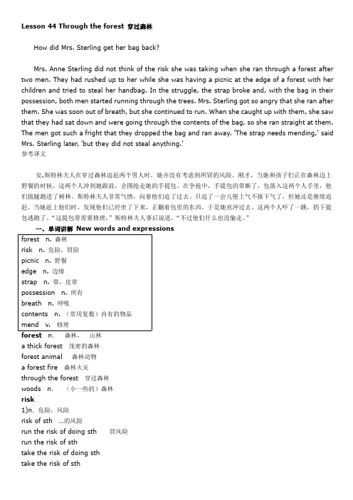
Lesson44Through the forest穿过森林How did Mrs.Sterling get her bag back?Mrs.Anne Sterling did not think of the risk she was taking when she ran through a forest after two men.They had rushed up to her while she was having a picnic at the edge of a forest with her children and tried to steal her handbag.In the struggle,the strap broke and,with the bag in their possession,both men started running through the trees.Mrs.Sterling got so angry that she ran after them.She was soon out of breath,but she continued to run.When she caught up with them,she saw that they had sat down and were going through the contents of the bag,so she ran straight at them. The men got such a fright that they dropped the bag and ran away.'The strap needs mending,'said Mrs.Sterling later,'but they did not steal anything.'参考译文安.斯特林夫人在穿过森林追赶两个男人时,她并没有考虑到所冒的风险。

目录1. 远程控制概述 (1)1.1 如何远程控制 (1)1.2 通信协议 (3)1.3 远程控制功能 (5)2. SCPI简介 (10)2.1 命令格式 (10)2.2 符号说明 (10)2.3 参数类型 (11)2.4 命令缩写 (12)3. 模式共用命令 (13)3.1 IEEE公用命令子系统 (13)3.2 系统命令 (15)3.3 存储命令 (20)3.4 显示控制 (21)3.5 模式命令 (22)3.6 扫描命令 (22)4. 频谱分析模式 (24)4.1 仪器模式命令 (24)4.2 Initiate命令子系统 (24)4.3 Sense命令子系统 (25)4.4 Calculate命令系统 (43)4.5 Measurement命令系统 (58)4.6 触发 (72)4.7 TG (73)4.8 调制解调 (75)5. 矢量网络分析模式 (77)5.1 频率控制 (77)5.2 幅度控制 (78)5.3 带宽控制 (80)5.4 扫描控制 (80)5.5 TG (81)5.6 迹线 (81)5.7 光标 (85)6. 故障定点分析模式 (98)6.1 频率控制 (98)6.2 幅度控制 (99)6.3 扫描控制 (100)6.4 迹线 (101)6.5 光标 (102)6.6 测量 (105)7. 调制分析模式 (110)7.1 频率控制 (110)7.2 幅度控制 (111)7.3 带宽控制 (112)7.4 扫描控制 (113)7.5 迹线 (114)7.6 光标 (117)7.7 测量 (119)7.8 触发 (124)8. 实时频谱分析模式 (126)8.1 频率控制 (126)8.2 幅度控制 (129)8.3 带宽控制 (131)8.4 扫描控制 (132)8.5 迹线 (134)8.6 光标 (137)8.7 触发 (139)8.8 测量 (142)9. EMI测量 (145)9.1 频率控制 (145)9.2 幅度控制 (147)9.3 带宽控制 (150)9.4 扫描控制 (151)9.5 迹线 (153)9.6 光标 (155)9.7 限制 (159)10. 编程示例 (168)10.1 使用VISA的编程示例 (168)10.2Sockets/Telnet示例 (182)SIGLENT 1. 远程控制概述分析仪支持通过USB、LAN、GPIB-USB接口与计算机进行通信。

精梳技术2内容3内容4精梳: 获得高品质纱线的正确方法16条并卷 TSL 1226精梳机 TCO 1252Disclaimer在实现更高纱线品质及更高经济性的路上,纺织车间不断面临越来越大的挑战,比如:专业人士缺乏,如何实现高度灵活的生产以及实现资源的最佳应用等。
自公司成立之日起,我们就基于自己的价值观为您提供:“获得高品质纱线的正确方法”。
我们不断研发全新的技术解决方案。
使用这些方案,您可以跟上市场中的风云变幻,由此保证您的企业保持长盛。
在这里,我们为您提供实用的创新技术与自我优化功能,助您走上“获得高品质纱线的正确方法”的道路。
获得高品质纱线的正确方法真正的纱线品质源自一整套精准严密的流程● D UAL DRIVE 和 2 TWIN DRIVE 使精梳头间的波动减少 54%,而精梳质量更趋稳定● C OUNT CONTROL - 自动质量检查实现更高的棉条质量●最佳的牵伸系统几何形状实现完美的 CV 值正确的道路4节约资源的关键:● 在 TSL 12 上,通过在 20 秒内更换棉卷实现更高的使用效率。
● 自动化棉卷运输设备用于更加集约的梳理装置组织● 与竞争对手相比,高效的抽吸系统和压缩空气系统可以节约 34% 的能源● 最佳的上罗拉轴承温度管理,保护涂层并延长使用寿命创新的、自主优化技术● 定时功能优化软钎焊时间点,无需进行费时费力的实验室测试● 曲线功能用于最佳的分离曲线● 自主调节的上罗拉棉卷监测器确保安全探测纤维卷绕正确的道路5自动运输手动喂棉手动运输半自动喂棉手动运输手动喂棉自动运输自动喂棉包含自动接断条互相完美匹配在特吕茨施勒梳理装置系统中,所有部件完美匹配运行。
换言之:请您重新定义自己对品质和经济性的期望。
SuperlapTruetzschler Superlap 可以根据不同的需求配置各种条桶架,以便满足 600 mm、1000 mm 直径喂入条桶和 JUMBO CANS 的不同要求。

Installation & Maintenance ManualOPERATION OF THD-SERIES JACKSCREWS FOR SPRING RETURN ACTUATIONINTRODUCTIONA-T Controls THD Jackscrews have been designed and engineered to provide a manual method of operating THD actuators.FOR YOUR SAFETY, IT IS IMPORTANT THAT BEFORE OPERATING THE THD JACKSCREW TO ENSURE THAT ALL LOCKOUT AND TAGOUT PROCEDURES ARE IMPLEMENTED. PLEASE CONSULT FACTORY IF YOU HAVE ANY QUESTIONS ON ANY OF THE PROCEDURES LISTED BELOW.1) Moving the Position of the Hand Wheel.WARNING: Before proceeding make sure the jackscrew is supported so that it does not fall when taking it apart.Remove the bolts on the gearbox (See Figure 1) and rotate the gearbox to the desired position. Reinstall the bolts back in the gearbox.2) Setting IndicatorThe Jackscrew indicator is set by the factory. Ensure that the Jackscrew 0º and 90º position is set properly after installation or if the stop bolts on the actuator have been adjusted. To run the actuator pneumatically the jackscrew must be in the 0º position. Check to make sure that the yoke makes contact with both stop bolts to ensure that the jackscrew is in the neutral position. For information on setting stop bolts refer to the THD IOM. To adjust the indicator, remove the stem cover by unscrewing the set screw and turning the stem cover counter-clockwise (See Figure 1). Once the stem cover is removed, adjust the nuts in the desired direction (See Figure 2).Figure 1Figure 2NEVER OPERATE THE ACTUATOR WHEN THE JACKSCREW IS NOT IN THE NEUTRAL POSITION. THIS COULD CAUSE DAMAGE TO THE ACTUATOR OR JACKSCREW.3) Operation of the Actuator A) Verify that the clockwise (CW) and counter-clockwise (CCW) supply ports on the actuator are not open to the atmosphere by turning the handles on the 3-way valves so that they are parallel to the air flow (see Figure 3).Figure 3B) Verify that the Jackscrew is in the 0º position (seeFigure 4).C) Applying air pressure to the CCW port drives the piston toward the front flange which turns the yokecounterclockwise when viewed from the accessory side of the actuator. When pressure is applied to the CW Port the piston is driven towards the end cap which turns the yoke clockwise. This is shown in Figure 3.Installation & Maintenance Manual4) Operation of JackscrewA) Verify that the clockwise and counter-clockwise supply ports on the actuator are open to the atmosphere by turning the handles on the 3-way valves so that they are perpendicular to the air flow (see Figure 3).B) To turn the valve in the clockwise direction, turn the hand wheel in the clockwise direction. To turn the valve in the counter-clockwise direction, turn the hand wheel counter-clockwise.C) Be sure before going back to pneumatic operation that the Jackscrew is set in the 0º position and both block and bleed valves are not open to the atmosphere.A-T Controls product, when properly selected, is designed to perform its intended function safely during its useful life. However, the purchaser or user of A-T Controls products should be aware that A-T Controls products might be used in numerous applications under a wide variety of industrial service conditions. Although A-T Controls can provide general guidelines, it cannot provide specific data and warnings for all possible applications. The purchaser / user must therefore assume the ultimate responsibility for the proper sizing and selection, installation, operation, and maintenance of A-T Controls products. The user should read and understand the installation operation maintenance (IOM) instructions included with the product, and train its employees and contractors in the safe use of A-T Controls products in connection with the specific application.While the information and specifications contained in this literature are believed to be accurate, they are supplied for informative purposes only. Because A-T Controls is continually improving and upgrading its product design, the specifications, dimensions and information contained in this literature are subject to change without notice. Should any question arise concerning these specifications, the purchaser/user should contact A-T Controls.For product specifications go to /A-T Controls, Inc. • 9955 International Boulevard, Cincinnati, OH 45246 • Phone: (513) 530-5175 • Fax: (513) 247-5462 • 。
Influence of creases: Like all T-splines and NURBS control points,creased control points influence the surface within a two faceregion. This means if only one edge is creased, the next two edgesin the loop will be partially creased, and the third edge away in theloop will not be creased at all. Array a. Edge to be creased b. After creasec. Enlarged image of (b) with Zebra stripes. How the crease blends into the surface. 1: Creasededge. 2&3: Edges partially creased from the influence of (1). 4: Beyond the region influenced bythe crease, a smooth surface.Crease behavior near star points: The influence of creases produ-ces some undesirable effects near star points. If any edge of a starpoint is creased, all the edges going out of the star point will becreased as well—and so will points up to three edges away. Thus,it is recommended to either crease all edges of a star point or noedges of a star point—or, to just use the tsInsertEdge command toinsert a soft crease near the star point.Edge of a T-spline box Sharp crease added with tsCrease. Tangency handles appear(when set to visible in tsOptions). Notice the crease alsoextends down the third edge of the star point.Soft creasesSometimes when “creases” are prescribed, a tight radius edge, ra-ther than a perfectly sharp crease, is desired. Soft creases, also refe-rred to as “edge weighting” by polygonal modelers, can be createdwith the tsInsertEdge command.Sharp crease (tsCrease)Soft crease (tsInsertEdge)A soft crease on a corner: Rather than insert a sharp crease, insertan edge. Inserting these edges close to the original edge will provi-de an effect of a soft creaseEdge of a T-spline boxEdge loop (highlighted) inserted with tsIn-sertEdge for a tight radius (.05)Edge loop inserted with tsInsertEdge for tight radius (.2)Edge loop inserted with tsInsertEdge for tight radius (.4)A soft crease on an extrusion: When extruding a column, you cancontrol the curvature on the top and the bottom of the column by inserting edge loops with tsInsertEdge (or doing multiple extru-sions). The edge loops can then be moved to determine the tight-ness of the curvature.ExtrusionEdge loop inserted at top for a tighter radius...…and one on the bottom, too.Adding surfaceExtrude faceSelect a face or faces. Run the tsExtrude command. When the facesare moved by the manipulator, a column of new faces will be addedaround the original face, connecting it to the surface.Before During AfterExtruding multiple faces: Two or more adjacent faces extruded to-gether will be extruded as a single column. To make a gap betweenextruded faces, extrude them separately.Two faces extruded, one at a timeTip Extruding non-rectangular facesSometimes it is desirable to extrude a non-rectangular face to get more control over the sides of the extrusion. Here is one way to create and extrude a cylindrical 6-sided face:Select an edge Delete the edge Select two pointsScale 1D the points outwardsSelect the faceExtrude the faceTwo more extrusions. The extrusion is oblong because there are two T-points on the sides.In the tsLayout com-mand Click the “T”s to turn them to star points; exit the commandNow the extrusion is balancedExtruding with symmetry: To extrude across a symmetry boun-dary, select faces on both sides of the symmetry border. If just one face is selected, separate extrusions will be made on each side of the symmetry border.Extruding across symmetryExtrude edgeExtruding edges allows you to add more geometry on the bordersof your model. To use this command, select an edge or edges to beextruded and run the tsExtrude command. Extruding edges is onlypermitted on the edge of the surface.Select entire border Run tsExtrude Move the edgesSingle edges can be extruded, or an entire border can be extruded.Select edge or edges to extrude Run tsExtrude Move the edgeTip Extruding edges to smooth T-splines bordersIf the edge of your T-spline model has a crease, this is how to fix it.This is a very important tip that will greatly improve your modeling!T-spline surface Two edges extruded. Noticethat the surface has creases;this is because the bordercontains a sharp inner corner,which pushes a crease to therest of the surface throughthe isocurves. One way to make thiscreased surface smooth isadding a complete borderloop. Select all borderedges (above).Extrude the border edges.Notice that the topology of theborder changes and all borderpoints now have a valence 3,which is the best for smoothcontours.Extrude curveIn T-Splines 2.2, curves can be extruded. Just select the curve and run the tsExtrude com-mand.Tip Extruding with the manipulatorInstead of clicking the Extrude icon, justselect your object (curve, face, or edge),hold down the ALT key, and drag themanipulator to make an extrusion. Thisworks with the translate, rotate and scalemanipulators!ThickenThe tsThicken command is a quick way to approximately shell orgive thickness to a surface.Before Thickened (smooth borders)tsThicken does not give exact shelling; instead, it creates an edi-table solid with minimal control points. For exact shelling, use theRhino OffsetSrf command, which is accurate to within the filetolerance.Thickening open surfaces: The thicken command will take a sur-face and thicken it by duplicating the surface and connecting the two surfaces around the edges. The user can specify the thickness by either entering a number into the command prompt or moving the mouse and clicking. The thickness is measured according to thesurface normal for each control point.Open T-spline surfaceThickened 3 units, uncreased edgesThickened 3 units, creased edgesThe DirectionType option allows you to thicken Normal to the surfa-ce or normal to each vertex (PerVertexNormal ).T-spline surface Thicken (Normal)Thicken (PerVertexNormal)OptionsThe CreaseEdges option allows for creased or smoothed edges on the thickened surface.Thickening closed surfaces: If the surface is closed, the Thicken command creates a second, separate surface.The T-spline is thickened again, yielding the red surface. With clipping plane to show both surfaces.Creating self-intersecting surfaces with Thicken: tsThicken does not check to see if it creates a self-intersecting object; in fact, if the inputted thickness is greater than the minimum curvature of the object, the model will self-intersect. We recommend visually exami-ning your model for self intersections after thickening it. Self inter-sections can be resolved by manually moving control points.Duplicate facestsDuplicateFaces makes a copy of T-spline faces. This willcopy the locations of the control points. If you are in boxmode, it will look like an exact copy, but if you are in smoo-th mode, if you are copying an open selection, the borderedges of the selection may have different curvature fromthe original surface.Select faces to duplicate A new surface will be createdDeleting detail/surfaceDeleteThe Delete command lets you remove faces, edges, and verticesfrom your model.Deleting faces will delete the surface. Deleting faces is an alternative to trimming, and leaves an editable model.Deleting edges and vertices from a model will produce changes ofcurvature.Deleting edges removes them from the surface. This is similar to Rhino’s RemoveKnot command, except that partial edges can be deleted as well.Deleting a vertex will also remove any edges touching the vertex.Tip Use the Delete key on your keyboard instead of clicking the icon for deletions!Deleting faces vs. trimming: Deleting faces is a new concept fortraditional NURBS modelers. This is an alternative to trimming thesurface. Unlike trimming, though, deleting a face will actually remo-ve it from the surface and leaves definite surface edges with control points, whereas trimming “hides” the trimmed part of the surface.See more examples of deleting faces vs. trimming in the TrimmingT-splines section.Trimming curve and surface to be trimmed.End result after Rhino Trimoperation. Surface is “turnedoff” but original control pointsstill exist.End result after deleting T-splines faces. Surface edges lieon the trimming curve.How to delete faces to make a “trimless” T-splineDelete all faces through which the curve traverses.After deletion Select border edges.Extrude the edges.Match the edges tothe curve.“Trimless” T-spline One benefit of havinga true surface edge isthat it can be extruded.For greater control,subdivide faces befo-re deletion.Select border edges.Extrude the edgesand reposition.“Trimless” T-splineDeletions that yield invalid surfaces: Most deletions can beperformed in either smooth or box mode. However, some deletionswill produce an invalid surface, and the T-spline will automaticallyswitch to box mode upon deletion. In these instances, the T-splinewill need to be repaired before it can be displayed in smooth mode.Deleting faces that touch only at corners: If a face is deleted,leaving other faces that only touch at a corner, the surface will beinvalid in smooth mode and will only be able to be displayed in boxmode.Invalid surface (faces only touching atcorners). Red dots indicate the surfacecannot be displayed in smooth mode.Adding this face will make the surfacevalid.A valid surface.TipHow to make a hole in a T-spline with smooth cornersFace to be deleted.Deleted face. Corners aresharp.Select all border edges. Extrude all border edges. Thehole is now circular withoutsharp corners.Remove creasesThe tsRemoveCreases command removes creases in the T-splinesurface. Creases are defined in T-Splines by tangency handles,when the tangency handles are deleted the surface is smoothed.To use the command, select a creased edge or point and run thecommand. The crease will be deleted, and the surface will becomesmooth.Before Wireframe of “Before” showing tangencyAfterhandlesCombining surfacesFill holeThe tsFillHole fills holes in the T-spline surface. To fill a hole, clickon an edge of the hole while in the command. The model remainseditable as a single surface.Filling a single hole.Hole in T-spline surface Hole filled with tsFillHole commandMultiple holes can be filled at once.Three separate holes can be filled at one. Here one edge from each hole is preselected. The holes are filled by running the tsFillHole com-mand.Filling oddly-shaped holes.Even strangely shaped holes can be filled with the tsFillHole command.The hole is filled. However,additional edges should beinserted using tsInsertPointbecause this is an oddlyshaped n-sided face and willnot smooth as desired.The highlighted edges wereinserted.Final smooth surface.Weld pointsThe tsWeld command allows you to weld points inside a single T-spline, or to combine two T-splines into one.Before AfterIf two points are preselected, the weld command will average thedistances between themIf the points are selected after the command is run, the first pointwill be moved to the position of the second point.When points of two different T-splines are welded, or when closinga gap in a single T-spline surface, the first pair of welded points will often turn red. A red point means that the smooth T-spline cu-rrently can’t be displayed. As soon as another point is welded in the edge, the red will disappear and the smooth T-spline will be able to be displayed.More advanced welding example. The first pair of points was preselected and each point was moved halfway for the weld. The second pair of points were individually post selected, first right then left, so the right point was moved to the left point during the weld. The third pair of points were post selected too, first left then right.Unweld edgestsUnweld will unweld edges of a T-spline. The unwelded edges will remain on top of each other until they are moved.Middle edges selected. After these edges are unwelded, theystill lie on top of each other. Edges are moved to show they are nolonger connected.AppendThe tsAppend command adds new faces to a T-spline. This is simi-lar to both the extrude edge command and the fill hole command. It is also possible to use this command to create a face unconnec-ted to any surface.Appending a face between two parts of a model.To append, select a point on the edge of the model where youwould like to start your appendage (it is beneficial to have Rhino’s Point Osnap turned on). Click points in space to mark the bounda-ries of the face to be appended, and then finish by snapping to a vertex on the same edge as the original point on the model.Using append face to create a face unconnected to any surface.BridgeThe Bridge command allows you to connect two T-spline surfaces (or two parts of the same T-spline surface) by adding intermediate faces. It consists of two steps: selection and alignment.Selection : The tsBridge command works on faces or border edges. In either case, two groups of faces or edges should be selected. If faces are selected, a bridge will be built between the borders of the selected regions, and the faces will be removed. You may switch between face or edge mode by using the SelectionMode com-mand option.Alignment : Specifies the number of segments that Bridge will cre-ate by using the Segments command option.You can toggle showing a mesh preview of the bridge by using the ShowPreviewcommand option.You may specify a curve along which the bridge will travel by using the FollowCurve command option. If a curve is selected, the com-mand will position and scale the curve so it will lie at the middle of the bridge and be scaled to fit between your selections. You may rotate the curve by using the Rotation command option, or by dragging the circle which is shown in the middle of the curve. The curve may be flipped by clicking the arrow that points outward from the center of the circle.Two faces to be bridged, without (left) and with ShowPreview turned on.From left: FollowCurve=no, FollowCurve=yes, resulting surface.The alignment between the two selections may be specified by clicking the alignment points on either group of edges or faces. If faces or edge loops are selected, all of the vertices along the selec-tion will be alignment points. Otherwise, the only alignment pointswill be at the ends of the edge selection. The alignment direction indicator will move to the selected alignment point.From left: alignment points are highlighted in the red boxes. The alignment direc-tion indicator can be clicked to swith direction; it can also be moved by clicking on other alignment points.Twist : The Bridge command works by imagining a tunnel which connects the two selected regions. If a bridge curve is selected, the tunnel travels along the curve, and the “up” direction follows the curvature of the curve. At intervals along the tunnel, Bridge takes a cross-section of the curve (called a frame) and determines where the bridge should be positioned within that frame. The Twist com-mand option allows you to specify how many complete rotations the tunnel will make around the curve between the beginning and the end of the tunnel. This can be used to make a bridge spiral, or to avoid pinching.With a twist of 0, a certain edge might have the following position in each of a series of frames, which leads to a pinched surface.With a twist of 0.5, the edge would stay at the same position, relative to each of the frames. The frame itself will change orientation, however, for a nicer spiral look.Merge edgesThe tsMerge command allows you to merge edges inside a single T-spline, or to combine two T-splines into one. To use the tsMerge command, select two chains of edges and merge them together.The Smooth option in tsMerge lets you determine whether the surfaces are merged smoothly or with a crease.1. Select border edge loops of surfaces A and B2. Merge edges3. Select border edgeloops of surfaces ABand C4. Merge edgesMerging edges of a single surface1. Select edges2. Merge them3. Select edges4. Merge them1. Select edges of both surfaces2. Merge them Merging post-selected edges1. Run the tsMerge command. Select edges of one surface, then select edges of second surface.2. The edges of the first surface will be moved to the location of the edges of the second sur-face, then they will be merged.1. Three different T-Spline surfaces.2. Select each row of edges toweld. Notice that the surfaceshave different number of ed-ges (2 on the left surface and 3on the right).3. The surface merges parame-trically, adding T –points alongthe merge region.4. Select edges to merge. Notice that you can merge a complete border of a surface against a partial edge of ano-ther surface.5. Having the same number ofedges on the border makes acleaner merge.6. It’s also possible to mergeedges of the same surface.Select edges.tsMerge is similar to tsWeld; however, tsMerge is unique in thatit lets you merge two surfaces with unmatching isocurves into asingle surface.7. Final T-spline surface.Match surfaceSimilar to the Rhino Match command, tsMatch will po-sition a T-Splines surface border edge to a Rhino NURBS surface or curve with Position , Tangent , or Curvature conti-nuity.Options (command line)Alignment optionsAdd : Adds a new connector to align.Delete : Deletes an existing alignment connector.FlipAlignmentDirection: Reverse the alignment direction.New conector on the alignmentAlignment direction revertedT-Splines (left) and NURBS (right) surfaces Match with Position continui-ty (G0)Tangent continuity (G1)Curvature continuity (G2)AlignmentType optionsParametric: Each point on the T-spline surface is matchedup to a point of a similar parametric distance along thematch target curve or surface.Arclength: The physical distance between each point onthe T-spline surface and the corresponding point on thetarget surface is minimized.Parametric alignment type Arclength alignment typeUseFallOff: Allows the user to determine how much of thesurface is affected by the match. If falloff is not used, thenthe surface will be minimally affected. If a falloff distance isentered, then the surface will be affected up to this distan-ce away.FallOffDistance: Determines how much of the surface isaffected by the match.Low falloff distance High falloff distanceUserRefinement: The Refine option will add control pointsto the T-spline to match the surfaces within a given tole-rance.T-Splines (inside) and NURBS (outside)Refine option= No Refine option = YessurfacesYou can also Match an interior (midsurface) edge of theT-Splines surface to a curve.Before tsMatch (Midsurface) After tsMatch (Midsurface)14. Modeling with symmetry tsSymmetryapplies axial or radial symmetry to a T-Splines surface.Axial symmetry: Allows symmetry in the X, Y and/or Z axis byplacing the symmetry axis. You can apply symmetry to a portion ofa model or to an entire model.Half model (credit: Ricardo Amaral) Symmetry applied; moving one side moves the otherOptions (command line)Weld: Determines whether to weld the vertices on the borders ofthe model. Weld=no will combine the parts into one object but notweld the vertices.Tolerance: If Weld=yes, all vertices on the symmetry border will bewelded if they fall within this tolerance.Discover: This option allow you to discover symmetry that alreadyexists in a completed model by selecting a middle edge (default),by selecting a face from each half of the symmetry (Faces option),or by selecting a face, an edge and a vertex from each side of thesurface.3Point: Allows you to determine the symmetry axis by selecting 3points.When a T-spline has symmetry enabled, the isocurves on the symmetry borders will be highlighted to show the sym-metry boundaries (default=green, the color can be changed in the tsOptions Display panel)Radial symmetry: Allows symmetry in a radialmanner by placing a center of rotation. You can apply symmetry to a portion of a model or to an entiremodel.Options (command line)Segments : Determines the number of radial portions of the symme-try.Radial symmetry with 8 segments.Weld : Determines whether to weld the vertices on the borders of the model or not. Weld=no will combine the parts into one object but not weld the vertices.Tolerance : If Weld=yes, all vertices on the symmetry border will be welded if they fall within this tolerance.Discover : This option allows you to discover radial symmetry on an entire surface by selecting a face from each portion of the symme-try (root and symmetric faces), or by selecting a face, an edge and a vert from each portion of the surface.tsSymmetryOffThis command is to remove symmetry from a surface. Just run thecommand and select the surface with symmetry.Options (command line)Isolate : This option allows you to turn symmetry off on just a part of the surface. Just select the on faces of the model to isolate from symmetry. Isolated faces will look pink. One note: only grips that are completely on the interior of the pink areas will have symmetry turned off. So in an example like this, where there are four faces with symmetry turned off, only the middle vertex that is completely surrounded by a symmetry-off region will truly have symmetry off. The border edges of the pink region will still have symmetry on.Part V:How to export T-splines14. Converting a T-spline to NURBS surfacesOne of the significant advantages of T-splines surfaces over subdivision surfaces is that converting T-splines to NURBS is a 100% precise, push-button solution that won’t deform the surface and maintains continuity. When you’re done using the T-splines tools to shape your model, convert it to NURBS to bring it into another program or to manufacture.tsConvertToRhinosurfThere are two ways to convert a T-spline surface to Rhino NURBS. The first way is to run the tsCon-vertToRhinosurf command. The second way is to just run a Rhino command. If the command requires a NURBS surface, the T-spline will be automatically converted to NURBS.One non-rectangular T-Splines surface.Multiple rectangular NURBS surfaces.The conversion of a T-spline to a NURBS requires that the T-spline be split into rectangular regions.To determine the smoothness and density of the NURBS, change the “Set star smoothness” option in the T-Splines option page. T-Splines are G1 smooth at star points; however, if the surface isn’t as visually smooth as desired at the star points, changing the star smoothness can help.Set surface layoutThe tsSetSurfaceLayout command allows the user to define the regions where the T-spline surface will be split into NURBS patches.By default, when T-spline surfaces are converted to NURBS, edges coming out of star points are extended to form the boundary of the NURBS patches, and all T-points within these areas are extended to form rectangular NURBS.The Set Surface Layout command gives the user an oppor-tunity to redefine how the T-spline is split into NURBS.When the command is entered, edges coming out of all star points in the model are highlighted with a dashed line. These edges must be on the edges of NURBS surfaces and cannot be deselected. The user can select any other edges in the model, and the selections will be the borders of NURBS patches after tsConvertToRhinosurf is run. The Default Extension option highlights all edges that would be the borders of NURBS by default. The Clear option clears the edge selection.tsSetSurfaceLayout UI. The dashed edges at star points must be border edges for the NURBS patches and cannot be dese-lected.Click on edges to set the desired layout Converting to NURBS will make the new layout patches T-Splines surface New layout with the Set Surface LayoutNURBS surfacecommand15. Converting a T-spline to a meshT-splines can be meshed for rendering or manufacturing with the tsMesh command, as well as the Rhino Mesh command. Also, T-splines can be exported as a low-poly .obj mesh.tsMeshtsMesh takes a T-spline as an input and produces a polygonal mesh.tsMesh usually exports a more optimized mesh for a T-spline than the Rhino Mesh command since tsMesh recognizes T-po-ints. tsMesh can also be used on NURBS and polysurfaces. OptionsUseTolerance determines whether to use a specified number of divisions per face, or fit to a tolerance.Tolerance is the tolerance value. The tsMesh command will output a mesh dense enough to be within this distance of theT-spline surface at every point.From left: T-spline surface; Polygonal mesh, tolerance=0.1; Polygonal mesh, tolerance=0.01.DivisionsPerFace is the number of divisions per T-spline face.If UseTolerance=No, then each face will be divided exactly thismany times and no more, even if significant detail is missing.A T-spline surface (above) converted to a mesh (bottom). From left: Divisions-PerFace: 1, 2, 3, 4.If UseTolerance=Yes, then the DivisionsPerFace will be a mini-mum number of divisions per face, but more divisions will beadded if necessary to obtain the required tolerance.Tip tsMesh works with Rhino’s history. Click Record History before entering this command, and modifications made on the T-spline object will be updated live on the mesh object.Rhino Mesh commandThe Rhino Mesh command will work on a T-spline just as it works on Rhino NURBS and polysurfaces. See the Rhino help for moreinstructions on this command.Export T-spline mesh as a quad-dominant .objSelect the T-spline in box mode, and then export as an .obj. The exported mesh will be mainly quads, except that faces with T-points on them will be triangulated.From left: Box mode T-spline, smooth T-spline in Rhino.From left: Mesh exported to subdivision surface modeler. (The arrows point out that faces with T-points on them are triangulated in a subdivision surface modeler). Smoothed mesh in subdivision surface modeler.Part VI:Advanced modeling with T-Splines16. Advanced edit mode: hotkeys and selectionT-splines introduces a new “edit mode” inside Rhino that contains optimized tools for pushing and pu-lling the surface.Edit mode can be turned on and off by clicking the T-Splines edit mode icon.Most of the features of edit mode are discussed in the edit mode section . Three additional features will be explained here: hotkeys, advanced selection, and the multiplier.Hotkeys Hotkeys are enabled by default whenever you are in edit mode. To turn off hotkeys, just click the blue text in the heads-up display. When hotkeys are enabled, the keyboard cannot be used to type Rhinocommands, unless the mouse cursor is positioned in the command line field.T-Splines manipulator and selection commands are assigned hotkeys by default.Using hotkeys yields significant speed advantages when doing serious tweaking on a T-spline mode. With one hand using the mouse and the other changing grip modes and manipulators and calling com-mon commands using hotkeys, your iteration time will shrink dramatically. Hotkeys can be assigned to both T-Splines and Rhino commands in the T-Splines hotkeys options.Other T-Splines commands can be selected from the pull down list on the bottom and assigned hotkeys.。
Prepared on 24 November 2020Tessier五步提该流程分为5步,先后分别提取5态。
第1态为可交换态(ExchangeableFraction)指交换吸附在沉积物上的粘土矿物及其他成分(如氢氧化铁!氢氧化猛!腐殖质上的重金属),对环境变化非常敏感, 易于迁移转化,能被植物吸收。
由于水溶态的金属浓度常低于仪器的检出限,因此普遍将水溶态和可交换态合起来计算,也叫水溶态和可交换态。
可交换态重金属反映人类近期排污的影响以及对生物的毒性作用。
奚2态为碳酸盐结合态(Carbonate-Bound Fraction ),指碳酸盐沉淀结合的一些重金属。
对土壤环境条件特别是pH值最敏感,当pH值下降时易重新释放出来而进入环境中相反,pH值升高有利于碳酸盐的生成。
第3态为铁猛水合氧化物结合态(Fe-Mn Oxides-Bound Fraction ),此形态重金一般是以矿物的外曩物和细分散颗粒存在,活性的铁猛氧化物比表面积大,吸附或共沉淀阴离子而形成。
土壤中pH值和氧化还原条件的变化对铁猛氧化物结合态有重要影响,pH值和氧化还原电位较高时,有利于铁猛氧化物的形成。
铁猛氧化物结合态反映人文活动对环境的污染。
第4态为有机物和硫化物结合态(Organio-Bound Fraction ),亦即有机物结合态,指颗粒物中的重金属以不同形式进入或包裹在有机质颗粒上同有机质鳌合等或生成硫化物。
有机结合态重金属反映水生生物活动及人类排放富含有机物的污水的结果。
奚5态为残余态(Residual Fraction ),—般存在于硅酸盐、原生和次生矿物等土壤晶格中,是自然地质风化过程的结果。
在自然界正常条件下不易释放,能长期稳定在沉积物中,不易为植物吸收。
残余态的重金属主要受矿物成分及岩石风化和土壤侵蚀的影响。
Tessier 5步顺序提取流程(g样品)如下:文子:⑴可交换态(EXC):向样品中加入8 ml M MgC12溶液(pH二)} 2511 0C 下连续振荡lh;于4000 r/min下离心10 min ,过滤出上清液,加5 ml去离子水洗涤残余物,再于4000 r/min下离心10 min ,过滤出上清液;将所有上清液于50 ml 比色管中定容z ICP-OES测定重金属浓度。