KabelSchlep(佳宝莱)电缆拖链选型
- 格式:pdf
- 大小:3.79 MB
- 文档页数:36
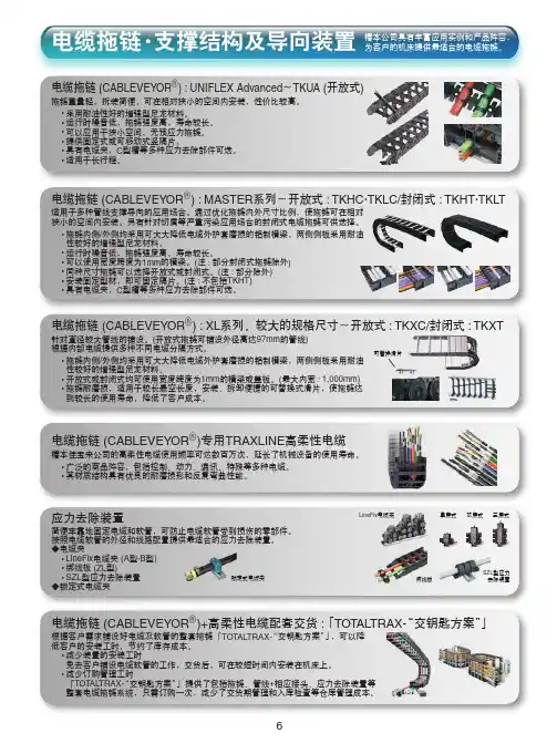
电缆拖链 (CABLEVEYOR R ) : UNIFLEX Advanced ~TKUA (开放式)拖链重量轻,拆装简便,可在相对狭小的空间内安装,性价比较高。
• 采• 运• 可• 提• 具• 适用于长行程。
电缆拖链•支撑结构及导向装置椿本公司具有丰富应用实例和产品阵容,为客户的机床提供最适合的电缆拖链。
电缆拖链 (CABLEVEYOR R )+高柔性电缆配套交货 :「TOT ALTRAX-“交钥匙方案”」根据客户需求铺设好电缆及软管的整套拖链「低客户的安装工时,节约了库存成本。
• 减免去客户铺设电缆软管的工作,交货后,可在较短时间内安装在机床上。
• 减「整套电缆拖链系统,只需订购一次,减少了交货期管理和入库检查等仓库管理成本。
应力去除装置简便牢靠地固定电缆和软管,可防止电缆软管受到损伤的零部件。
按照电缆软管的外径和线路配置提供最适合的应力去除装置。
◆电缆夹• L • 绑• SZL ◆锁定式电缆夹电缆拖链 (CABLEVEYOR R ) : MASTER 系列~开放式 : TKHC ·TKLC/封闭式 : TKHT ·TKLT 适用于多种管线支撑导向的应用场合。
通过优化拖链内外尺寸比例,使拖链可在相对狭小的空间内安装。
另有针对切屑等严重污染应用场合的封闭式电缆拖链可供选择。
• 拖链内侧/外侧均采用可大大降低电缆外护套磨损的铝制横梁,两侧侧板采用耐油性较好的增强型尼龙材料。
• 运行时噪音低,拖链强度高,寿命较长。
• 可以使用宽度跨度为1mm 的横梁。
(注 : 部分封闭式拖链除外)• 同种尺寸拖链可以选择开放式或封闭式。
(注 : 部分除外)• 安装固定型材,即可固定隔片。
(注 : 不包括TKHT)• 具有电缆夹,C 型槽等多种应力去除部件可选。
电缆拖链 (CABLEVEYOR R )专用TRAXLINE 高柔性电缆椿本佳宝来公司的高柔性电缆使用频率可达数百万次,延长了机械设备的使用寿命。
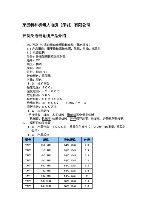
荣缆特种机器人电缆(深圳)有限公司控制类拖链电缆产品介绍1.800万次PVC高速运动电源拖链电缆(黑色外皮)1.1产品用途:用于拖链系统电源,阻燃,耐油,高柔性1.2 电缆结构导体:多股超细精绞无氧铜丝绝缘:PVC填充:棉线绕包:绵纸外被:耐油PVC护套颜色:雾面黑芯线:彩色1.3技术参数额定电压:300V温度范围:-5-80℃放电检测:2KV特性阻抗:90±15%Ω绝缘电阻:DC 500V 100MΩ/Min弯折次数:800万次1.5产品包装:100M/R重量仅供参考(100M/R的重量,单位为公斤)2.1产品用途:用于拖链系统电源,阻燃,耐油,高柔性2.2 电缆结构导体:多股超细精绞无氧铜丝绝缘:PVC填充:棉线绕包:绵纸外被:耐油PVC护套颜色:灰黑芯线:彩色2.3技术参数额定电压:300V温度范围:-5-80℃放电检测:2KV特性阻抗:90±15%Ω绝缘电阻:DC 500V 100MΩ/Min弯折次数:800万次2.5产品包装:100M/R重量仅供参考(100M/R的重量,单位为公斤)3.1产品用途:用于拖链系统电源,阻燃,耐油,高柔性3.2 电缆结构导体:多股超细精绞无氧铜丝绝缘:PVC填充:棉线绕包:绵纸外被:耐油PVC护套颜色:雾面黑芯线:彩色3.3技术参数额定电压:300V温度范围:-40-80℃放电检测:2KV特性阻抗:90±15%Ω绝缘电阻:DC 500V 100MΩ/Min弯折次数:1000万次3.5 产品包装:100M/R重量仅供参考(100M/R的重量,单位为公斤)4.1000万次PVC高速运动电源屏蔽拖链电缆(黑色外皮带屏蔽)4.1产品用途:用于信号传输,抗干扰,阻燃,耐油,高柔性4.2 电缆结构导体:多股超细精绞无氧铜丝绝缘:高机械性能PVC混合物填充:棉线绕包:绵纸外被:低粘性PVC基混合物屏蔽:镀锡铜网编织屏蔽,屏蔽率90%以上护套颜色:雾面黑芯线:彩色芯(2-8芯)黑色编码(10-30芯)4.3技术参数额定电压:300V温度范围:-40-80℃放电检测:2KV特性阻抗:90±15%Ω绝缘电阻:DC 500V 100MΩ/Min弯折次数:1000万次4.4 应用场合适用于物流设备系统、五金冲压、机械手、建筑机械、码头、消防车、汽车制造、木材石材加工设备、机床加工等。


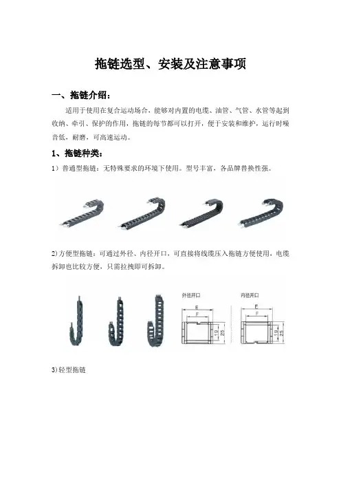
拖链选型、安装及注意事项一、拖链介绍:适用于使用在复合运动场合,能够对内置的电缆、油管、气管、水管等起到收纳、牵引、保护的作用,拖链的每节都可以打开,便于安装和维护,运行时噪音低,耐磨,可高速运动。
1、拖链种类:1)普通型拖链:无特殊要求的环境下使用。
型号丰富,各品牌替换性强。
2)方便型拖链:可通过外径、内径开口,可直接将线缆压入拖链方便使用,电缆拆卸也比较方便,只需拉拽即可拆卸。
3)轻型拖链4)加强型拖链、三维型拖链加强型拖链:可应用于负载较重,长距离、告诉运动、环境恶劣的工况。
三维型拖链:多维运动,小弯曲半径,全封闭防碎屑,链节可拆卸。
2、拖链常用名词解释1、桥式:链节两侧只有横杆连接的结构2、半封闭型:连接一侧封闭,一侧桥式结构,一般为外侧封闭式、内侧为桥式。
3、全封闭式:拖链内外侧均为封闭式结构。
4、打开方式:拖链横杆是否可以打开,方便线缆填装,分为不可打开、内侧开口、外侧开口、内外侧开口。
5、梳状板:用于固定接头处固定管、线,以减少接头处管线的应力。
6、分隔片:用于拖链内部不同类型的管、线。
二、拖链选型1、确定拖链内部尺寸电缆、气管和液压管等负载的数量、类型及直径决定了拖链的内部尺寸和分配状况。
首先,要保证负载的拖链内部合理均匀的分布:包括重量均匀分布,空间合理分布。
若为单一负载且只有一条,空间足够即可(见图一);拖链(图一)若为液压管、水管、气管、油管和电缆等不同的负载最好用竖隔片分隔开来(见图二);若为同种负载数量较多且直径差异比较大,也最好用竖隔片隔开(见图二);拖链(图二)若有多层排布,可用横隔片在高度方向进行分隔(见图三)。
拖链(图三)其次,要保证负载能够在拖链内部能够自由移动,防止排布时产生相互缠绕的现象;然后,根据负载的排布,计算出内高和内宽:通常情况下所选用的拖链的内宽和内高为负载排布的最大高度和最大宽的1.5倍;最后,根据拖链的使用环境决定是否需要选用全封闭拖链(一般情况下在有粉尘颗粒较大或者环境较为恶劣的情况下,为了更好的保护负载,可选用全封闭型的拖链)。

众所周知,建筑电气电缆敷设所用的金属“槽盒”或“桥架”或“托盘”,各个规范的叫法五花八门,各个图集也没有统一名词用法,各个设计院或项目工程人员也是各有口语表达,没有一个固定的叫法,使得业内人员无所适从。
本文对“槽盒”、“桥架”、“托盘”等名词与对应产品进行了详细介绍,包括设计图纸表示方法与产品选用原则,并对其防火措施进行了介绍。
域规范用词下面带大家浏览•下各有千秋的叫法,规范及名词使用如下:GB50054-20U《低压配电设计规范》用词:电缆托盘和梯架GB50116-2013《火灾自动报警系统设计规范》用词:线槽GB50217-2018《电力工程电缆设计标准》用词:电缆支架、梯架或托盘JGJ242-2011《住宅建筑电气设计规范》用词:金属线槽、桥架GB51348-2019《民用建筑电气设计标准》用词:槽盒、桥架、弱电金属线槽GB50311-2016《综合布线系统工程设计规范》用词:金属管槽GB51309-2018《消防应急照明和疏散指示系统技术标准》用词:槽盒GB55024-2023《建筑电气与智能化通用规范》用词:金属槽盒通过列举几本工程常用规范,可以看出每个规范都有自己的用词,那么这些所谓的桥架、槽盒、托盘、梯架是否都是同•类产品?是否仅仅是叫法不同而实际产品相同?是否每个名字都有对应厂家产品?圆实际产品下面我们就看一下业内厂家的产品介绍。
国内某厂家产品如下,通过直观的产品展示,我们对于这些产品会有一个直观的认知,会帮助我们分辨各种名词所对应的产品。
金属梯架托盘式桥架槽式桥架槽式桥架水平弯通国产品选用原则各种产品的应用原则是什么呢?不同产品有自己独特的应用领域?是的,正是由于应用原则和领域不同,才会产生出这么多不同名称的产品,下面具体介绍如下:梯式桥架,简称梯架非封闭式,重量轻,成本低,散热透气好,适用于低压强电非消防电缆、高压电缆。
托盘式桥架,简称托盘非封闭式,承载大,散热透气好,适用于低压强电非消防电缆、高压电缆。

高明电缆拖链技术参数高明电缆拖链技术参数作为机床的重要附件之一,电缆拖链是连接设备与机器人等设备的重要元件,而高明电缆拖链作为电缆拖链的品牌之一,其技术参数必须得到充分的了解和掌握。
下面我们将详细介绍高明电缆拖链的技术参数。
1.外观尺寸高明电缆拖链的外观尺寸从10mm到300mm不等,长度也不固定,可以根据不同的需求进行调整。
根据机器设备的规格及安装位置不同,需要有不同尺寸可供选择,以达到最佳的适配效果。
2.速度范围高明电缆拖链的速度范围在5米/秒到20米/秒之间,可以适应不同的机器设备速度。
对于高速运转的机器设备,可以选择速度较快的电缆拖链来确保其稳定性和使用寿命。
3.弯曲半径高明电缆拖链的弯曲半径也是关键技术指标之一。
不同尺寸的电缆拖链具有不同的最小弯曲半径,最小弯曲半径越小,电缆拖链的可弯曲性就越好。
在机器设备不断进行移动的过程中,必须考虑到其运动的全方位性能,对弯曲半径的掌握要尽可能做到精准。
4.负载能力负载能力是电缆拖链的重要参数之一,高明电缆拖链最高的负载能力为30kg/m左右,适用于不同的负荷需求。
在使用过程中,需要在可接受的范围内控制载荷,以确保电缆拖链的使用寿命和稳定性。
5.防护等级高明电缆拖链的防护等级可达到IP40-IP65级别,可以防护泥沙、水、尘埃等外部破坏因素的进入,保证电缆拖链内部电缆线的安全和可靠。
6.耐腐蚀性高明电缆拖链的材质采用高质量的耐腐蚀性化学材料,可以承受不同气氛和酸碱等腐蚀性环境的影响。
7.耐磨性能高明电缆拖链的耐磨性能也十分突出,在多次使用和折叠的过程中,其内部电缆线可以得到很好的保护,使其使用寿命更长。
8.温度范围高明电缆拖链的温度范围为-40度到120度之间,可以适应不同温度环境下的机器设备使用,使设备性能稳定可靠。
综上所述,高明电缆拖链的技术参数十分完备,可以根据不同机器设备的需要进行合理选择,从而达到最佳的使用效果。
在使用过程中,需要按照生产厂家的使用说明来进行正确的安装和操作,以确保电缆拖链的安全、可靠和稳定。

拖链选型手册
拖链选型手册:
1.拖链的用途:避免电缆及介质管在运动的过程中与机床相接触。
2.拖链管线排布:管线在拖链中最理想的状态是排成一排,并预留30%的空间,直径差别很大的电缆及介质管应分隔铺设,可采用分隔片实现隔离。
在任何情况下都不允许电缆及介质管在拖链中相互纠缠。
3.电缆或介质管两端都应使用梳状板、电缆夹等去应力元件。
固定电缆最好使用电缆夹。
拖链尽量每一节都能够打开,当高速运动时,一般不选用佳吉的拖链,选用igus的。


电缆保护链选型及安装注意事项1.电缆保护链(后简称拖链):✧适合于使用在往复直线运动场合,能够对内置的电缆,气管,油管,水管等起到牵引和保护作用,拖链每节都能打开便于安装和维修;✧可防止连接在设备活动部位的电缆,因运动而发生纠缠,磨损,拉脱,散乱;✧安装方式:2.电缆选型:2-1 选用高抗弯强度的柔性专业拖链电缆。
2-2 根据实际需要合理选择电缆的弯曲半径,运行速度,温度范围,屏蔽等级等。
3.拖链选型:3-1 拖链类型(按照拖链开口方向区分)3-1-1 外径开口3-1-2 内径开口3-1-3 不可开口3-1-4 内外径开口3-2 拖链内高,内宽尺寸3-2-1 内高度:确保电缆等外径在拖链内部高度的80%以内。
3-2-2 占有面积:确保电缆等收藏量在拖链的内容量=内部高度*内部宽度的60%以内。
3-2-3 弯曲半径:同时收藏不同种类电缆等,请根据其中弯曲半径最大者选择拖链的弯曲半径、3-2-3 拖链弯曲半径定义:将拖链折叠成上下两层,然后找到拖链的最高点跟最他低点。
然后量一下两个关节的距离。
然后这两者间的一半就是拖链的弯曲半径了。
3-3 拖链自由伸缩长度:根据所需移动行程与固定端的设置位置,计算自由伸缩长度。
3-3-1 自由伸缩长度是指拖链移动端(A)与弯曲半径圆弧起点(B)之间的距离。
3-3-2 将自由端设置在移动行程的中间点时,自由伸缩长度=移动行程/2,拖链的链数也最少。
3-3-3 我们目前设计主要以拖链固定端方便走线为主。
4.安装注意事项:4-1 电缆安装时,不能有扭曲,线盘和线圈不能从上端开始放线。
4-2 排列电缆时,必须使其延长度方向能自由移动。
4-3 电缆必须在拖链的弯曲部分运动自如,当上拖链达到最大净长度时必须仔细检查。
4-4 电缆必须松散的并排敷设在拖链中,尽可能分开排列,用隔片分开或穿入支架空挡的分离空洞中,在拖链中电缆间的空隙至少应为电缆直径的10% 。
4-5 拖链中的电缆不得相互接触或困在一起。
拖链选型指导书序号修改内容概述修改人修改日期备注年—月—日拖链设计指导书一:拖链的用途纠正:电缆及介质管扎成一捆是错误的使用方法。
拖链适合于使用在往复运动距离较大的场合,能够对内置的电缆、油管、气管、水管等起到牵引和保护作用。
电缆及介质管在运动的过程中,允许的弯曲半径不同,使用拖链可以将不同弯曲半径的电缆及介质管统一在拖链的弯曲半径上,保护大弯曲半径的电缆及介质管。
拖链可以避免电缆及介质管在运动的过程中与机床相接触。
二:拖链管线排布管线在拖链中最理想的状态是排成一排,并预留30%的空间(可能后增加电缆及介质管),直径差别很大的电缆及介质管应分隔铺设,可采用分隔片实现隔离。
在任何情况下都不允许电缆及介质管在拖链中相互纠缠。
电缆或介质管重量应该沿着拖链宽度方向对称分布,使用不同外保护套材料的电缆及介质管不得相互接触。
电缆及介质管两端都应使用梳状板,电缆夹等去应力元件。
固定电缆最好使用电缆夹。
拖链中的竖隔片、横隔片可以将不同种类及保护材料的电缆及介质管分隔开,(豪森要求,基本要将气管,强电电缆,弱电电缆分隔开)避免它们在拖链内部之间的相互摩擦。
拖链尽量每一节都能够打开(不能打开的拖链,客户一般不允许使用)。
当高速运动时,一般不选用佳吉的拖链。
选用igus的。
1、拖链的安装形式:水平,垂直(立式,挂式),侧向安装,旋转运动2、受力曲线图:三:拖链的选型1、选型步骤:确定安装方式(悬空、垂直、侧面、旋转等运动)确定行程长度确定拖链的尺寸(根据机器设备具体安装空间与装填物如:电缆数目/电缆外径,分隔方式,确定拖链尺寸—内高、内宽、弯曲半径,拖链长度,节数)校核架空长度及负载(是否在建议采用的应用范围)确定打开方式(一侧打开、两侧打开、沿内径快速打开、沿外径快速打开等)确定分隔片数量确定去应力紧固装置形式(电缆夹,梳状板)3、拖链的选型原则:内高:选择内置电缆、油管、气管、水管等中直径最大的一根定作D,拖链的内高为hi,则hi=1.1D。
拖链电缆的组成和安装要求在设备单元需要来回移动的场合,为了防止电缆纠缠、磨损、拉脱、挂和散乱,常把电缆放入电缆拖链中,对电缆形成保护,并且电缆还能随拖链实现来回移动,这种可以跟随拖链进行来回移动而不易磨损的高柔性专用电缆便叫拖链电缆,通常也可称之拖曳电缆,坦克链电缆。
拖链电缆主要应用于:工业电子系统,自动生成线,仓储设备,机器人,消防系统,起重机,数控机床和冶金工业。
拖链电缆组成1.抗拉中心在电缆的中心根据芯数数量以及每根芯线交叉区域的空间里尽可能的有一个真正的中心线填充(而不是像通常情况下,用一些填充料或废塑料制成的垃圾芯线填充)这种方法能有效的保护绞线结构,防止绞线游离到电缆的中心区域。
2.导体结构电缆应该选择最具柔韧性的导体,一般来说导体越细,电缆的柔韧性越好,但导体过细,会产生电缆缠绕现象。
一系列长期的实验提供了单根导线的最佳直径,长度和节向的屏蔽组合,它有最佳的抗拉能力。
3.芯线绝缘电缆内的绝缘材料不能彼此粘滞。
而且绝缘层还需要支撑每股单股的导线。
因此只有在高压成型的PVC或者TPE材料才能用于拖链的数百万米电缆中的应用过程中证实他的可靠性。
4.绞线绞线结构必须以最佳的交合节距绕在一个稳定的抗拉中心周围。
然而由于绝缘材料的应用,绞线结构应按运动状态设计,从12根芯线开始,因该采用成束绞合的方式。
5.内护套甲胄式挤压成型的内护套取代廉价的羊毛材料,填充物或附属填充物。
这一方法能保证绞线结构不会散乱。
6.屏蔽用优化的编织角度将屏蔽层紧紧的编织在内护套外,松散的编织带会降低EMC的保护能力并且屏蔽层也很快因屏蔽的断裂而失效。
紧密编织的屏蔽层同时具有抗扭力的作用。
7.外护套由不同的改良材料制成的外护套具有不同的功能,有抗UV功能的,有抗低温功能的,有耐油的以及成本优化的。
但所有的这些外护套都有一个共同点,高耐磨性,并不会粘附任何东西。
外护套必须是高柔性的但也要有支撑功能,当然应该是高压成型的。
三水电缆拖链技术参数
三水电缆拖链是一种常用的电缆保护装置,主要可以将电缆整齐地布置在一起,保护电缆不受外界环境的影响,同时也能够有效地防止电缆弯曲、拉伸等情况的发生。
下面是三水电缆拖链的技术参数:
1、拖链外形尺寸:长度、宽度、高度和弯曲半径等。
2、耐磨性:拖链应具有耐磨的特性,以保证长期使用不受损。
3、强度:拖链应具有足够的强度,以承受电缆的重量和外界环境的冲击。
4、耐腐蚀性:拖链应能够抵抗腐蚀,以延长使用寿命。
5、温度范围:拖链应适用于特定的温度范围,以保证在不同环境下的正常使用。
6、阻燃性:拖链应具有防火的特性,以保障电线电缆的安全。
7、导电性:拖链应具有良好的导电性能,以保证电缆的传输效率和稳定性。
8、噪音降低:拖链应具有降低电缆传输时的噪音的功能,以提高使用环境的舒适性。
以上就是三水电缆拖链的技术参数,这些参数的优劣将直接影响到电缆拖链的使用效果和寿命。
因此,企业在选购电缆拖链时,需要根据自身需求选择适合的型号和品牌。
- 1 -。
13.1• Metal side-bands made of extremely durable stainless or plated steel • Quick and easy cable installation• Available with twist on/off reinforced aluminum frame stays•Available with bolted-on heavy-duty aluminum or plated steel frame stays• Available with bolted-on heavy-duty aluminum frame stays with frictionless Delrin ® rolling surfaces • Available with made-to-order bored aluminum bars• Vertical and horizontal cable separation in nylon or aluminum •Mounting brackets allow for surface or face connection optionsVARITRAK SsteelcarriercablesystemSteel cable carrier system13V A R I T R A K S13.2Speci fi cations are subject to change without notice.KS-1106-GC-ASelf-Supporting Lengthssystems, KS Support Rollers or major credit cards acceptedA product group’s EVA score is a general indicator that allows a customer to quickly and easilyFor more information onextended travel systems, see pages 2.27-2.36Number of Systems Req.8x x +-+++-+++-xx Type & Position Brackets M A I /F A I # of Links Length 32 Links T ype Frame Stay RS2Dividers(#vert / #horz)5v/0hBend Radius 135Carrier TypeS0650.1Cavity Width 10.00”(B i )VARITRAK S steel• open style • customizable widthsNeed help?1-800-443-4216or 13VARITRAKS 13.3Specifi cations are subject to change without notice. KS-1106-GC-ASeries S 0650.1 Features one twist in/out aluminum bar on the outer radius and one bolted-on aluminum bar on the inner radius per frame stay.Usable Cavity Widths (B i)are available from2.00” (50.8 mm)through 12.00” (304.8 mm).Ten standard width sizes are available from stock. Custom widths are also available in any width increment required by the customer.RS1 Bar Systemdividers can be slid into position13V A R I T R A K S13.4Speci fi cations are subject to change without notice.KS-1106-GC-AFeatures bolted on aluminum bars on both the outer radius and the inner radius per frame able Cavity Widths (B i ) are available from 2.00” (51 mm) through 12.00” (304.8 mm).Ten standard width sizes are available from stock. Custom widths are also available in any width increment required by the customer.RS2Bar SystemMounting Bracket OptionsFor detailed drawings anddimensions of available options, please see pages: 13.32 - 13.33dividers can be slid into position0.12(3)=s TStandard RS2STYLE Vertical Divider=B i + 0.63 (16)=B i + 1.22 (31)h iRecommendedMAXIMUMWidthRecommendedMINIMUMWidthh G h G Note: For extended widths, multiple chain-band designs factory:1-800-443-42160.51(13)PN:44250S0650.1 - 2.00” - RS2 - (KR) - (# of links) - (brackets) - (dividers)S0650.1 - 12.00” - RS2 - (KR) - (# of links) - (brackets) - (dividers)bars on outside radiusB st = Cut bar length B k = Outer chain width B i = I nner chain cavity(usable) width h G = Outer chain link height h i = I nner chain cavity(usable) height S T = Vertical divider thicknessVARITRAK Ssteel • open style • customizable widthsNeed help? 1-800-443-4216 or 13V A R I T R A K S13.5Speci fi cations are subject to change without notice.KS-1106-GC-ASeriesS 0650.1Features bolted-on heavy-duty split and bored aluminum bars.Bar Widths (B st ) are available from 2.50” (63.5 mm) through 19.00” (482.6 mm) in any width increment required by the customer.LGBar System• B y simply unscrewing 1 bolt per split-bar at bothends of each bar and sliding out the unbolted split-bar, cables & hoses can be easily installed (laid inside, in each speci fi cally designed 1/2 round).• I deal when unique cables and hoses must beindividually separated.Why use LG system13V A R I T R A K S13.6Speci fi cations are subject to change without notice.KS-1106-GC-AWhen application travel exceeds major credit cards acceptedDDEDA product group’s EVA score is a general indicator For more information onextended travel systems,see pages 2.27-2.36Number of Systems Req.4x x +-+++-+++-xx Type & Position Brackets M A I /F A I # of Links Length 35 Links T ype Frame Stay RMR Dividers(#vert / #horz)9v/0hBend Radius 170Carrier TypeS0950Cavity Width 18.00”(B i )VARITRAK Ssteel • open style • customizable widthsNeed help? 1-800-443-4216 or 13V A R I T R A K S13.7Speci fi cations are subject to change without notice.KS-1106-GC-ASeriesS 0950Features one twist in/out aluminum bar on the outer radius and one bolted-on aluminum bar on the inner radius per frame stay.Usable Cavity Widths (B i ) are available from 3.00” (76.2 mm) through 11.00” (279.4 mm).Ten standard width sizes are available from stock. Custom widths are also available in any width increment required by the customer.RS1Bar Systemh G =B i + 0.94 (24)=B i + 1.69 (43)dividers can be slid into position0.16(4)=s TStandard RS1STYLE Vertical Dividerh iRecommendedMINIMUMWidth0.55(14)PN: 42160S0950 - 3.00” - RS1 - (KR) - (# of links) - (brackets) - (dividers)B st = Cut bar lengthB k = Outer chain width B i = I nner chain cavity(usable) width h G = Outer chain link height h i = I nner chain cavity(usable) height S T = Vertical divider thickness13V A R I T R A K S13.8Speci fi cations are subject to change without notice.KS-1106-GC-AMounting Bracket OptionsFor detailed drawings anddimensions of available options, please see pages: 13.32 - 13.33dividers can be slid into position0.16(4)=s TStandard RS2STYLE Vertical DividerB st B k =B i + 0.71 (18) =B i + 1.46 (37)h iRecommendedMAXIMUMWidthRecommendedMINIMUMWidthh G h G Note: For extended widths, multiple chain-band designs factory:1-800-443-42160.55(14)PN: 42160S0950 - 3.00” - RS2 - (KR) - (# of links) - (brackets) - (dividers)S0950 - 14.00” - RS2 - (KR) - (# of links) - (brackets) - (dividers)bars on outside radiusB st = Cut bar lengthB k = Outer chain width B i = I nner chain cavity(usable) width h G = Outer chain link height h i = I nner chain cavity(usable) height S T = Vertical divider thicknessFeatures bolted on aluminum bars on both the outer radius and the inner radius per frame able Cavity Widths (B i ) are available from 3.00” (76.2 mm) through 14.00” (355.6 mm).Ten standard width sizes are available from stock. Custom widths are also available in any width increment required by the customer.RS2Bar SystemVARITRAK Ssteel • open style • customizable widthsNeed help? 1-800-443-4216 or 13V A R I T R A K S13.9Speci fi cations are subject to change without notice.KS-1106-GC-ASeriesS 0950Features heavy-duty double bolted-on aluminum bar on the outer radius and on the inner radius per frame stay.Usable Cavity Widths (B i ) are available from 3.00” (76.2 mm) through 23.00” (584.2 mm) in any width increment required by the customer.RMSBar Systemdividers can be slid into position0.16(4)=s TStandard RMS STYLE Vertical DividerRecommendedMAXIMUMWidthRecommendedMINIMUMWidthNote:factory:1-800-443-4216h G st k =B i + 0.71 (18) =B i + 1.46 (37)h ih G 0.57(14.5)PN: 42130S0950 - 3.00” - RMS - (KR) - (# of links) - (brackets) - (dividers)S0950 - 23.00” - RMS - (KR) - (# of links) - (brackets) - (dividers)bars on outside radiusB st = Cut bar lengthB k = Outer chain width B i = I nner chain cavity(usable) width h G = Outer chain link height h i = I nner chain cavity(usable) height S T = Vertical divider thickness13V A R I T R A K S13.10Speci fi cations are subject to change without notice.KS-1106-GC-AFeatures heavy-duty double bolted-on aluminum bar with integrated roller system on the outer radius and on the inner radius per frame stay.Usable Cavity Widths (B i ) are available from 3.00” (76.2 mm) through 22.00” (558.8 mm) in any width increment required.RMRBar SystemVARITRAK Ssteel • open style • customizable widthsNeed help? 1-800-443-4216 or 13V A R I T R A K S13.11Speci fi cations are subject to change without notice.KS-1106-GC-ASeriesS 0950Features bolted-on heavy-duty split and bored aluminum barsBar Widths (B st ) are available from 3.00” (76.2 mm) through 23.00” (584.2 mm) in any width increment required by the customer.LGBar SystemMounting Bracket OptionsFor detailed drawings anddimensions of available options, please see pages: 13.32 - 13.3313V A R I T R A K S13.12Speci fi cations are subject to change without notice.KS-1106-GC-Amajor credit cards acceptedsystems, KS Support Rollers orDDEDA product group’s EVA score is a general indicator that allows a customer to quickly and easilyFor more information on extended travel systems,see pages 2.27-2.36Number of Systems Req.10x x +-+++-+++-xx Type & Position Brackets M F/F F # of Links Length 27 Links T ype Frame Stay RS1Dividers(#vert / #horz)11v/2hBend Radius 260Carrier Type S1250Cavity Width 22.00”(B i )VARITRAK Ssteel • open style • customizable widthsNeed help? 1-800-443-4216 or 13V A R I T R A K S13.13Speci fi cations are subject to change without notice.KS-1106-GC-ASeries1250 Sh G =B i + 0.94 (24)=B i + 1.89 (48)h iRecommendedMINIMUMWidthdividers can be slid into position0.20(5)=s TStandard RS1STYLE Vertical Divider0.59(15)PN: 42900dividers can be slid into positionS1250 - 4.00” - RS1 - (KR) - (# of links) - (brackets) - (dividers)B st = Cut bar lengthB k = Outer chain width B i = I nner chain cavity(usable) width h G = Outer chain link height h i = I nner chain cavity(usable) height S T = Vertical divider thicknessFeatures one twist in/out aluminum bar on the outer radius and one bolted-on aluminum bar on the inner radius per frame stay.Usable Cavity Widths (B i ) are available from 4.00” (101.6 mm) through 14.00” (355.6 mm).Ten standard width sizes are available from stock. Custom widths are also available in any width increment required by the customer.RS1Bar System13V A R I T R A K S13.14Speci fi cations are subject to change without notice.KS-1106-GC-Adividers can be slid into position0.20(5)=s TStandard RS2STYLE Vertical Divider=B i + 0.79 (20)=B i + 1.73 (44)h iRecommendedMAXIMUMWidthRecommendedMINIMUMWidthh G h G Note: For extended widths, multiple chain-band designs factory:1-800-443-42160.59(15)PN: 42900S1250 - 4.00” - RS2 - (KR) - (# of links) - (brackets) - (dividers)S1250 - 18.00” - RS2 - (KR) - (# of links) - (brackets) - (dividers)bars on outside radiusB st = Cut bar lengthB k = Outer chain width B i = I nner chain cavity(usable) width h G = Outer chain link height h i = I nner chain cavity(usable) height S T = Vertical divider thicknessFeatures bolted on aluminum bars on both the outer radius and the inner radius per frame able Cavity Widths (B i ) are available from 4.00” (101.6 mm) through 18.00” (457.2 mm).Ten standard width sizes are available from stock. Custom widths are also available in any width increment required by the customer.RS2Bar SystemVARITRAK Ssteel • open style • customizable widthsNeed help? 1-800-443-4216 or 13V A R I T R A K S13.15Speci fi cations are subject to change without notice.KS-1106-GC-ASeries1250 SFeatures heavy-duty double bolted-on aluminum bar on the outer radius and on the inner radius per frame stay.Usable Cavity Widths (B i ) are available from 4.00” (101.6 mm) through 30.00” (762 mm) in any width increment required by the customer.RMSBar System13V A R I T R A K S13.16Speci fi cations are subject to change without notice.KS-1106-GC-AFeatures heavy-duty double bolted-on aluminum bar with integrated roller system on the outer radius and on the inner radius per frame stay.Usable Cavity Widths (B i ) are available from 4.00” (101.6 mm) through 30.00” (762 mm) in any width increment required.RMRBar SystemVARITRAK Ssteel • open style • customizable widthsNeed help? 1-800-443-4216 or 13V A R I T R A K S13.17Speci fi cations are subject to change without notice.KS-1106-GC-ASeriesFeatures bolted-on heavy-duty split and bored aluminum bars.Bar Widths (B st ) are available from 4.00” (101.6 mm) through 30.50” (774.7 mm) in any width increment required by the customer.LGBar SystemMounting Bracket OptionsFor detailed drawings anddimensions of available options, please see pages: 13.32 - 13.3313V A R I T R A K S13.18Speci fi cations are subject to change without notice.KS-1106-GC-AFeatures medium-duty double bolted-on aluminum bar compatible with integrated easy snap-in vertical and horizontal divider system.Usable Cavity Widths (B i ) are available from 4.00” (101.6 mm) through 21.00” (533.4 mm) in any width increment required.RVBar SystemVARITRAK S steel• open style • customizable widthsNeed help?1-800-443-4216or 13VARITRAKS 13.19Specifi cations are subject to change without notice. KS-1106-GC-A SeriesThe carrier cavity width can be easily divided vertically - so cables or hoses can be safely separated side by side - next to one another. If small cables are to be stacked or cables with varying diameters are being used, the option to add horizontal shelving to properly accommodate these can be easily done by simply adding a shelf at the height desired. The various vertical levels that are available for the horizontal shelves are defined in this catalog section. The applicable kit components part numbers (dividers and shelves) are clearly identified.Varitrak 1250 RV Horizontal Shelving- optional widths(5.8)Horizontal shelves can be easily pressed and locked into placebetween the specially designed RV vertical dividers. This makeshorizontal and vertical partitioning of the carrier’s cavity easyto install and highly fl exible to meet your application’s uniqueneeds.13V A R I T R A K S13.20Speci fi cations are subject to change without notice.KS-1106-GC-Amajor credit cards acceptedDDEDA product group’s EVA score is a general indicator systems, KS Support Rollers or Self-Supporting Lengthskg m lbs ft 6040.3For more information on Number of Systems Req.8x x +-+++-+++-xx Type & Position Brackets M A I /F A I # of Links Length 85 Links T ype Frame Stay RMS Dividers(#vert / #horz)9v/1hBend Radius 435Carrier TypeS1800Cavity Width 18.00”(B i )VARITRAK Ssteel • open style • customizable widths13V A R I T R A K SSeries1800 SFeatures heavy-duty double bolted-on aluminum bar on the outer radius and on the inner radius per frame stay.Usable Cavity Widths (B i ) are available from 6.00” (152.4 mm) through 37.00” (939.8 mm) in any width increment required by the customer.RMSBar System13V A R I T R A K SFeatures heavy-duty double bolted-on aluminum bar with integrated roller system on the outer radius and on the inner radius per frame able Cavity Widths (B i ) are available from 6.00” (152.4 mm) through 38.00” (965.2 mm) in any width increment required.RMRBar SystemVARITRAK Ssteel • open style • customizable widths13V A R I T R A K SSeries1800 SFeatures bolted-on heavy-duty split and bored aluminum barsBar Widths (B st ) are available from 6.00” (152.4 mm) through 39.00” (990.6 mm) in any width increment required by the customer.LGBar SystemMounting Bracket OptionsFor detailed drawings anddimensions of available options, please see pages: 13.32 - 13.33B st = Cut bar length B k = Outer chain width h G = Outer chain link heightD max = Maximum hole diameter C min = M inimum distancebetween holesa o min = M inimum hole offset from end13V A R I T R A K Ssystems, KS Support Rollersmajor credit cards acceptedDDEDA product group’s EVA score is a general indicator that allows a customer to quickly and easilyFor more information on extended travel systems,see pages 2.27-2.36Number of Systems Req.10x x +-+++-+++-xx Type & Position Brackets M A/F I # of Links Length 63 Links T ype Frame Stay RMS Dividers(#vert / #horz)15v/3hBend Radius 760Carrier TypeS2500Cavity Width 30.72”(B i )VARITRAK Ssteel • open style • customizable widths13V A R I T R A K SSeries2500 SFeatures heavy-duty double bolted-on aluminum bar on the outer radius and on the in-ner radius per frame stay.Usable Cavity Widths (B i ) are available from 7.00” (177.8 mm) through 56.00” (1422.4 mm) in any width increment required by the customer.RMSBar Systemdividers can be slid into position0.31(8)=s TStandard RMS STYLE Vertical DividerRecommendedMAXIMUM WidthRecommendedMINIMUM WidthNote:factory:1-800-443-4216h G h G = B st B k B i =7.00(177.8)8.30(210.8)9.52(241.8)8.66(220)=B i + 1.30 (33) =B i + 2.52 (64)7.20(183)=h iB st =B k =S2500 - 7.00” - RMS - (KR) - (# of links) - (brackets) - (dividers)S2500 - 56.00” - RMS - (KR) - (# of links) - (brackets) - (dividers)B st = Cut bar length B k = Outer chain widthB i = I nner chain cavity(usable) width h G = Outer chain link height h i = I nner chain cavity(usable) height S T = Vertical divider thickness13V A R I T R A K SSeries2500 SFeatures bolted-on heavy-duty split and bored aluminum barsBar Widths (B st ) are available from 8.50” (215.9 mm) through 46.00” (1168.4 mm) in any width increment required by the customer.LGBar SystemMounting Bracket OptionsFor detailed drawings anddimensions of available options, please see pages: 13.34 - 13.35B st = Cut bar lengthB k = Outer chain width h G = Outer chain link heightD max = Maximum hole diameter C min = M inimum distancebetween holesa o min = M inimum hole offset from endVARITRAK Ssteel • open style • customizable widths13V A R I T R A K SName: Date: Dept.: Phone:Fax:Company: Machine Type/Name:Address:13V A R I T R A K Smajor credit cards acceptedsystems, KS Support Rollers can be used to extend travel.Self-Supporting Lengths150101S 3200kgm lbs ftUnsupported LengthDDEDA product group’s EVA score is a general indicator For more information on extended travel systems, see pages 2.27-2.36Number of Systems Req.10x x +-+++-+++-xx Type & Position Brackets M I/F I # of Links Length 42 Links T ype Frame Stay LG # ofHoles33Bend Radius 1275Carrier TypeS3200Bar Width42.50”(B st )VARITRAK Ssteel • open style • customizable widths13V A R I T R A K SSeries3200 SFeatures bolted-on heavy-duty split and bored aluminum bars.Bar Widths (B st ) are available from 10.50” (266.7 mm) through 57.00” (1447.8 mm) in any width increment required by the customer.LGBar SystemMounting Bracket OptionsFor detailed drawings anddimensions of available options, please see pages: 13.34 - 13.35RecommendedMAXIMUMWidthNote:factory:1-800-443-4216h G S3200 - 57.00” - LG - (KR) - (# of links) - (brackets) - (holes)B st = Cut bar length B k = Outer chain width h G = Outer chain link heightD max = Maximum hole diameter C min = M inimum distancebetween holesa o min = M inimum hole offset from end13V A R I T R A K SVaritrak Series S/SX 5000, 6000, 7000 and LargerDo you have an application that is super-sized? KabelSchlepp has a long and successful history of supplying Super-Duty Cable and Hose Carrier systems in a wide range of industries and applications. Using standard components and proven technologies, KabelSchlepp Super-Duty Steel Cable and Hose Carrier Systems can be custom manufactured to meet your individual application requirements. Call your KabelSchlepp factory representative at 1-800-443-4216 for complete information and design assistance!• Rugged Super-Duty systems that can be scaled to meet EXTREME size and load requirements.• A vailable in high-grade galvanized (Type S) or stainless steel (Type SX) with a variety of environment andapplication speci fi c coatings.• U tilizing standard components and cutting edge manufacturing technology, systems can be designed, manufactured and installed in record time.• Select from a wide variety of frame stay and partitioning options custom con fi gured to your unique needs.• W ork with a team of dependable and experienced engineers who understand the unique requirements ofsuper-duty applications to ensure project success.SUPER-DUTY Steel Cable and Hose Carrier SystemsVARITRAK Ssteel • open style • customizable widthsNeed help? 1-800-443-4216 or 13V A R I T R A K S13.31Speci fi cations are subject to change without notice.KS-1106-GC-ADimensional DataSeries(t ) Link Pitchh i maxh GB k minB k maxS/SX 5000t = 7.87 (200) 5.91 (150)7.87 (200)9.84 (250)47.24 (1200)S/SX 6000t = 12.60 (320)9.45 (240)11.81 (300)11.81 (300)59.06 (1500)S/SX 7000t = 17.72 (450)14.57 (370)17.72 (450)13.78 (350)70.87 (1800)Larger systems and special designs are possible. Call your KabelSchlepp factory representative at1-800-443-4216 for complete information and design assistance!General Data for Super-Duty Steel SystemsAvailable Bend Radii (KR)SeriesBend Radii (KR)S/SX 500019.69 (500)23.62 (600)31.50 (800)39.37 (1000))47.24 (1200)S/SX 600027.56 (700)35.43 (900)43.31 (1100)51.18 (1300)59.06 (1500)S/SX 700043.31 (1100)49.21 (1250)59.06 (1500)70.87 (1800)94.49 (2400)Application speci fi c bend radii are possible upon request.Dimensions in inches (mm)Dimensions in inches (mm)Self-Supporting LengthK RWhen a Super-Duty carrier system’s self-supporting length is exceeded, KabelSchlepp can incorporate a KS Rolling Carriage System to provide adequate support over the entire distance of travel. See Extended Travel Systems section of the Technical Handbook pages 2.27-2.36 for more information.13V A R I T R A K S13.32Speci fi cations are subject to change without notice.KS-1106-GC-AStandard Mount - Fixed End BracketsStandard Mount - Moving End BracketsSize a b c d e f g h i j k S0650B k + 0.98 (25)B k – 1.45 (37)0.68 (17)0.51 (13) 1.18 (30)0.12 (3)0.20 (5)0.59 (15) 1.77 (45) 3.74 (95)0.25 (6.4)S0950B k + 1.93 (49)B k – 2.48 (63) 1.18 (30)0.98 (25) 2.16 (55)0.15 (4)0.39 (10)0.79 (20) 2.55 (65) 4.91 (125)0.33 (8.4)S1250B k + 1.81 (46)B k – 2.52 (64) 1.18 (30)0.98 (25) 2.16 (55)0.19 (5)0.39 (10)0.98 (25) 3.14 (80) 6.09 (155)0.41 (10.5)S1800B k + 2.08 (53)B k – 3.03 (77)1.38 (35)0.98 (25)2.36 (60)0.19 (5)0.39 (10)1.18 (30)4.52 (115)8.25 (210)0.51 (13)Size lm n o p q r s t u v S0650B k + 0.75 (19)B k – 1.69 (43)0.68 (17)0.51 (13) 1.18 (30)0.12 (3)0.20 (5)0.59 (15) 1.77 (45) 3.74 (95)0.25 (6.4)S0950B k + 1.61 (41)B k – 2.79 (71) 1.18 (30)0.98 (25) 2.16 (55)0.16 (4)0.39 (10)0.79 (20) 2.55 (65) 4.91 (125)0.33 (8.4)S1250B k + 1.41 (36)B k – 2.91 (74) 1.18 (30)0.98 (25) 2.16 (55)0.20 (5)0.39 (10)0.98 (25) 3.14 (80) 6.09 (155)0.41 (10.5)S1800B k + 1.61 (41)B k – 3.46 (88)1.38 (35)0.98 (25)2.36 (60)0.20 (5)0.39 (10)1.18 (30)4.52 (115)8.25 (210)0.51 (13)M K M HM A (Standard)M IF IF A (Standard)F HF KPlease specify the desired bracket variant and position when orderingExample: F A I /M A I (Standard) or F A A /M I AThe bracket positions at the Fixed End and Moving End can be changed later if required.Bracket EndM - Moving End F - Fixed EndBracket PositionA -c onnecting surface on outside radius (standard)I - c onnecting surface oninside radius H - c onnecting surface turned 90°to the outside radius K - c onnecting surface turned 90°to the inside radius F - face/flange mount (see opposite page)Varitrak S Standard BracketPosition OptionsAI (Standard)I (Standard)ABracket feet on the standard brackets can be positioned facing inward (I ) which is the standard position or facing outward (A ).Dimensions in inches (mm)Dimensions in inches (mm)VARITRAK Ssteel • open style • customizable widthsNeed help? 1-800-443-4216 or 13V A R I T R A K S13.33Speci fi cations are subject to change without notice.KS-1106-GC-AFace Mount - Fixed End BracketsFace Mount - Moving End BracketsSize ab c def ghij kl S0950B i + 4.84 (122.9)B i + 3.09 (78.5)-0.88 (22.4) 1.75 (44.5)0.16 (4)0.75 (19.1)0.50 (12.7) 3.00 (88.9)3.50 (88.9)0.41 (10.4)4.00 (101.6)S1250B i +5.27 (133.9)B i + 3.52 (89.4)-0.88 (22.4) 1.75 (44.5)0.18 (4.6)0.75 (19.1)0.50 (12.7) 3.00 (88.9)3.50 (88.9)0.41 (10.5)4.00 (101.6)S1800B i + 7.39 (187.7)B i + 4.78 (124.4) 2.00 (50.8) 1.31 (33.3) 2.63 (66.8)0.20 (5.1) 1.00 (25.4)1.26 (32)3.00 (88.9)4.50 (114.3)0.56 (14.2)5.51 (140)Size mn o pqr stuv wx S0950B i + 4.52 (114.8)B i + 2.77 (70.4)-0.88 (22.4) 1.75 (44.5)0.16 (4)0.75 (19.1)0.50 (12.7) 3.00 (88.9)3.50 (88.9)0.41 (10.4)4.00 (101.6)S1250B i + 4.88 (124)B i + 3.13 (79.5)-0.88 (22.4) 1.75 (44.5)0.18 (4.6)0.75 (19.1)0.50 (12.7) 3.00 (88.9)3.50 (88.9)0.41 (10.5)4.00 (101.6)S1800B i + 6.92 (175.8)B i + 4.29 (109)2.00 (50.8) 1.31 (33.3) 2.63 (66.8)0.20 (5.1) 1.00 (25.4) 1.26 (32)3.00 (88.9)4.50 (114.3)0.56 (14.2)5.51 (140)Bracket EndM - Moving End F - Fixed EndBracket DesignationF - Face Mount Bracket (standard position)Varitrak SFace/Flange Mount BracketWhen specifying Varitrak S Face Mount Brackets, use the letter F for the Bracket Position designation of the assembly part number description.Example: F F/M FDimensions in inches (mm)Dimensions in inches (mm)13.34Speci fi cations are subject to change without notice.KS-1106-GC-AVARITRAK S Series Standard Mounting Brackets For S/SX 2500 & S/SX 3200KabelSchlepp mounting brackets for Varitrak S 2500 and 3200 series carriers are available in both standard steel (S) or high-grade stainless steel (SX).VARITRAK Ssteel • open style • customizable widthsNeed help? 1-800-443-4216 or 13V A R I T R A K S13.35Speci fi cations are subject to change without notice.KS-1106-GC-AVARITRAK S/SX 2500 & S/SX 3200 Bracket Position OptionsA (Standard)IBracket EndM - Moving End F - Fixed EndBracket PositionA -c onnecting surface on outside radius (standard)I - c onnecting surface oninside radiusPlease specify the desired bracket variant and position when ordering .Example: F A/M A (Standard) or F A/M IThe bracket positions at the Fixed End and Moving End can be changed later if required.VARITRAK S Series Mounting Brackets For S/SX 5000, 6000, & 7000KabelSchlepp mounting brackets for Varitrak 5000, 6000 and 7000 S/SX series carriers are available in both standard steel (S) or high-grade stainless steel (SX). Custom designed brackets per system requirements are also available. Call your KabelSchlepp factory representative at 1-800-443-4216 for complete information and design assistance!。