SINEEEM100操作手册
- 格式:pdf
- 大小:5.65 MB
- 文档页数:113

S100EM金属密码门禁一体机安装使用前仔细阅读本说明书1 产品简介:本产品为非接触式感应卡金属密码门禁一体机,根据型号不同分别支持EM、HID、MIFARE三种感应卡,是目前最先进的单门门禁控制器之一。
它采用独特的金属外壳设计,灵巧的键盘面板操作,内置高档微处理器,抗干扰能力强,安全性和可靠性极高,可为2000个用户提供强大的安全保障。
它具有超低功耗、夜光键盘、独立密码、韦根输出、输出短路保护、门磁报警、防拆报警、开门按钮、门铃接口、安全级别设置等强大功能,使用非常方便,可广泛应用于家庭、办公室、住宅小区及其它公共场所。
2 功能特点:超低功耗:待机电流小于30mA。
夜光键盘:夜晚也能操作键盘。
用户容量大:支持2000个用户。
独立密码:可使用与卡无关的密码开门。
用户修改密码:用户可自行修改开门密码。
搜索速度快:刷卡至开门时间小于0.1S。
输出短路保护:电锁或报警输出短路时100μS内自动关闭输出。
韦根输出:带有维根输出接口,能输出Wg26卡号或Wg4按键号。
可用键盘删除卡号:卡丢失后可用键盘删除该卡,彻底消除安全隐患。
防拆报警:非法拆机后内置蜂鸣器发出报警音。
有门铃按键和接口:按键与电路隔离,可外接任何门铃。
3技术参数工作电压:AC&DC9-28V静态电流:≤30mA读卡距离:3~8cm存储容量:2000个用户环境温度:-25℃~60℃环境湿度:10%~90%电锁输出:≤3A报警输出:≤20A输出短路保护时间:≤100μS开门时间:0~99秒(可调)外形尺寸:120 *80*25mm4管理员操作恢复出厂设置:断开电源打开后盖,用所配备的两脚短路插针,插进机器后方两位短路座,然后通电,机器“嘀嘀”两声后,接着取下短路插针,即为初始化成功。
(如图1)图1注:恢复出厂设置不会删除用户资料。
进入管理员操作状态:4.1 修改管理员密码:注:管理员密码为6~8位任意数字,请妥善保管好。
4.2 添加用户:4.2.1 连续增加卡:4.2.2 指定卡号增加:注:自动增加时,用户ID号由本机自动产生,范围是1~2000,并从小到大搜索。

Safety GuidelinesWarning notices must be observed to ensure personal safety as well as that of others, and to protect the product and the connected equipment. These warning notices are accompanied by a clarification of the level of caution to be observed.Qualified PersonnelThis device/system may only be set up and operated in conjunction with this manual. Qualified personnel are only authorized to install and operate this equipment in accordance with established safety practices and standards.Warning:This product can only function properly and safely if it is correctly transported, stored, installed, set up, operated, and maintained.Note: Always use product in accordance with specifications.This document is available in bound version and inelectronic version. We encourage users to purchase authorized bound manuals, or to viewelectronic versions as designed and authored bySiemens Milltronics Process Instruments Inc. Siemens Milltronics Process Instruments Inc. will not be responsible for the contents of partial or whole reproductions of either bound or electronic versions.While we have verified the contents ofthis manual for agreement with the instrumentation described, variationsremain possible. Thus we cannotguarantee full agreement. The contents of this manual are regularly reviewed and corrections are included in subsequent editions. We welcome all suggestions for improvement. Technical data subject to change.MILLTRONICS®is a registered trademark of Siemens Milltronics Process Instruments Inc. Contact SMPI Technical Publications at the following address:Technical PublicationsSiemens Milltronics Process Instruments Inc.1954 Technology Drive, P.O. Box 4225Peterborough, Ontario, Canada, K9J 7B1Email:************************Table of ContentsME100 Motion Probe: Introduction (2)Principle of operation (2)Specifications (3)Dimensions (4)Installation (5)Interconnection (6)Transient voltage protection (6)ME100 Positioning (7)ME100 Operational features (8)High/Low Alarm (HL) Model – Self Calibration (8)Zero Speed (ZS) Model (8)Applications (9)Bucket Elevators (9)Shafts (10)Belt Conveyors (10)Screw Conveyors (10)7ML19981EX01ME100 Motion Probe – INSTRUCTION MANUAL Page 1ME100 Motion Probe: Introduction Note: Please follow the installation and operating procedures to allow for themaximum accuracy and reliability of your ME100 Motion Probe.The ME100 Motion Probe is a safety device specifically designed to protect equipment that has rotating or reciprocating parts. The ME100 detects a changing magnetic field, typically caused by a ferromagnetic target disrupting the magnetic field of the probe1.The ME100 warns of an increase or decrease of motion by detecting alarm conditions.By detecting the disruption immediately, the ME100 protects equipment from damage or process failure.The ME100 is available in two models. The High/Low alarm version (HL) will detectwhether the speed of the monitored target is within a pre-set alarm band of the calibrated speed. The Zero Speed version (ZS) will alarm if the speed of the monitored target falls below 8 PPM (pulses per minute).Note: Before installing the ME100, ensure that the proposed location is free of anystrong 50/60Hz magnetic field caused by nearby power transformers, heater elements, or large industrial motors. These sources can affect the performance of the MotionProbe. (See note1 below).Principle of operationThe ME100 uses the principle of electromagnetic induction to detect the displacement ofa ferromagnetic object.The probe generates a magnetic field. When this magnetic field is disrupted by a moving ferromagnetic object, such as the bucket of a bucket elevator, the flight of a screwconveyor, or the keyway on a shaft, the coil of the probe generates voltage. This voltage is directly proportional to the strength of the field of the coil, the number of wire turns in the coil, and the speed of the ferromagnetic object. It is inversely proportional to the fourth power of the distance between the object and the coil.The voltage signal is conditioned to generate pulses for subsequent digital signalprocessing.1.Extremely strong magnetic fields (such as those produced by the 30A/mrequirements of IEC 61000-4-8 Power Frequency Magnetic Field Immunity Test)will be detected by the ME100. This will result in a loss of functionality whichmay cause the ME100 to falsely indicate alarm conditions by relay trip and/or achange in the color/state of the indicator LED.Page 2ME100 Motion Probe – INSTRUCTION MANUAL7ML19981EX01SpecificationsPower•24 Vdc (20–30 Vdc), 0.030 Adc maxOutput• 1 form C (S.P.D.T.) dry relay contact•Rated 1A at 50 VdcOperating RangeHigh/Low alarm (HL)•Standard: 2 to 480 PPM for rotating pulley, bucket elevators, drive sprockets•Optional: 0.5 to120 RPM for screw conveyor applications; 8 to1920 PPM (pulses perminute) for motor shaftsZero Speed (ZS)•8 to 1920 PPM, under-speed alarming below 8 PPMAlarm Band(HL version only)•Standard: ± 12% of calibrated 100% speed•Optional:± 3%, ± 6%, ± 25%, ± 50%Note: ± 50% offers under-speed alarming onlyProbe Sensitivity•Minimum distance 38 mm (1.5”) @ 0.6 m/min (2 ft/min) speed,with a target 50 mm (2") x 25 mm (1") and 25 mm (1") thickor•Minimum distance 76 mm (3”) @ 2.1 m/min (7 ft/min) speed,with a target 50 mm (2") x 25 mm (1") and 25 mm (1") thickOperating Temperature• –20 to +65o C (–4 to 149o F)• 5% to 95% Relative Humidity, No CondensationConstruction•Potted housing 316 stainless steel•Cable: 3m, 6 conductor, 22 AWG, shieldedIngress Protection•IP65Approvals•CE7ML19981EX01ME100 Motion Probe – INSTRUCTION MANUAL Page 3DimensionsME100 Motion Probe Dimensions (mm)Mounting Bracket Dimensions (mm)Page 4ME100 Motion Probe – INSTRUCTION MANUAL7ML19981EX01InstallationThe ME100 must be mounted in a non-hazardous area that is within the ambienttemperature range and is non-corrosive to the materials of construction (stainless steel enclosure and conduit).Note:•Use the bracket supplied to mount the ME100 onto a vibration-free structure.The gap between the probe and the target should be sufficient to prevent thetarget damaging the probe. If the target is enclosed by mild steel, a stainlesssteel “window” can be fabricated, to allow the sensor to read the target.•Use flexible conduit to connect the ME100, to make it easier to remove or adjust.7ML19981EX01ME100 Motion Probe – INSTRUCTION MANUAL Page 5Page 6ME100 Motion Probe – INSTRUCTION MANUAL 7ML19981EX01InterconnectionTransient voltage protectionThe input power supply lines of the ME100 are equipped with overvoltage protection circuitry. This circuitry protects the system from lightning, line transient and high voltage spikes, and provides a high degree of safety.Use a fuse to protect the relay contacts from excessive current flow.Cable Color Designation ColorFunction black- power supply negative red + power supply positivewhite relay commonblue relay normally open 1greenrelay normally closed 1orange shield/case ground 1.Relay energized: non-alarm stateME100 PositioningYou must be able to interrupt the 24 Vdc power supply to the ME100. If an ME100 N.O.relay contact is tied into the equipment control scheme, jumper the contact to allow the equipment to run.Locate the ME100 probe as shown in one of the application diagrams, and hand tighten the nuts and bolts which secure the clamping bracket. Ensure that any equipment guards are in place, then follow steps 1 to 6.1.Start up the equipment and run at desired speed2.Apply power to the ME100. The LED on the non-target end of the probe should pulsegreen, as each target passes by.3.If, instead of pulsing green, the LED illuminates red, shut down the equipment,interrupt power to the ME100 and re-position the probe target end closer to thetargets.4.Repeat step s 1, 2 and 3 until there is a green pulse for each target that passes by theprobe.The best position for the ME100 will be close enough to ensure high confidence inreading the targets, but far enough away to prevent the target, or any othertravelling components, from striking the ME100.5.Tighten the clamping bolts with wrenches to fully secure the ME1006.Remove power from the ME100, remove any contact jumpers and finalize wiring.The ME100 will now be ready to run when it is powered up again. We recommend that you apply power to the ME100 at the same time as, or after, you apply power to theequipment being monitored.Note:•The ME100 can be applied with the conduit nipple in any position, so long as the length of the probe is perpendicular to the targets.•Ensure the probe is mounted to a relatively vibration-free structure. High amplitude vibration may cause false pulses due the reaction of the probe to the Earth’smagnetic field.7ML19981EX01ME100 Motion Probe – INSTRUCTION MANUAL Page 7ME100 Operational featuresHigh/Low Alarm (HL) Model – Self Calibration Once the ME100–HL is powered, the alarm relay is energized, and the ME100 waits for the moving object to reach its nominal speed. There is a four-second delay, after which the first two pulses calibrate the system and the third verifies the calibration frequency.The ME100–HL is then armed and ready to detect and monitor motion variations.If the ME100–HL is unarmed and no motion is detected within a pre-set time limit (60 seconds divided by the minimum pulse rate of the model), or if the acknowledgement fails to confirm the speed, the alarm is activated and the relay de-energizes.Once armed, the ME100–HL continuously monitors the presence of incoming pulseswithin a pre-set tolerance, depending on the alarm band option. (±12% is standard.)The ME100–HL has two operating states indicated by a two color LED:•Normal: a green pulse on the LED indicates that the target has been detected,and that the pulse rate indicates proper operation•Alarm: a solid red LED indicates that the speed of the monitored target iswithin the alarm band of the calibrated speedThe alarm relay will re-energize if the speed of the monitored target returns to within the pre-set tolerance of the calibrated set point.Zero Speed (ZS) ModelOnce powered, the ME100–ZS energizes the alarm relay, which remains energized for a start up delay of 4 seconds, to allow the process to reach operating speed. If a pulse rate greater than 8 PPM is detected the relay remains energized, and the ME100–ZS is armed and ready to detect and monitor motion variations.The ME100–ZS has two operating states indicated by a two color LED:•Normal: a green pulse on the LED indicates that the target has been detected,and that the pulse rate indicates proper operation•Alarm: a solid red LED indicates that the pulse rate has dropped below the 8 PPM default setting, indicating loss of speedOnce the pulse rate exceeds the 8 PPM default setting, the alarm relay is re-energized, indicating proper operation.Page 8ME100 Motion Probe – INSTRUCTION MANUAL7ML19981EX01ApplicationsThe ME100 detects a target such as the bucket of a bucket elevator, the flight of a screw conveyor, or the keyway on a shaft. If the target is hard to distinguish, for example, a fine flight, or a shaft without a keyway, a ferrous mass can be added to provide a clear target. Bucket Elevators1.For Belt-Driven Elevators with ferrousbuckets spaced at intervals greater than76mm (3"), or non-ferrous buckets withferrous bolts, locate the ME100 on theback of the down leg.2.For ferrous buckets spaced at intervalsless than 76mm (3"), locate the ME100on the front of the down leg.3.For Chain and Sprocket Drive Elevators,locate the ME100 so that the gapbetween the bucket and the sensor enddoes not exceed 102mm (4"). To preventdamage to the ME100 from eccentricbucket motion, ensure that the gap is notless than 12.5mm (0.5") in the worstconditions.4.For elevators with ferrous walls, cut aME100(See detail A)Down LegPage 10ME100 Motion Probe – INSTRUCTION MANUAL 7ML19981EX01ShaftsA keyway or paddle blades may be used as a target when the shaft speed is sufficient for the blades or key to provide the number of pulses required at a minimum velocity of1.5m/minute (5ft/minute). In applications where exposed moving parts cannot be avoided, take precautions, and provide safety shields.Belt ConveyorsLocate the ME100 so that the gap from the sensor end to the target is a maximum of 102mm (4"). The optimum distance is 25 mm to 51mm (1" to 2"). The potential for damage in each application governs the minimum gap allowable.Screw ConveyorsIf the target is difficult to detect, (for instance if the flight is very fine), you can add a ferrous mass behind the flight of the screw conveyor where it passes the ME100, to improve detection in borderline conditions. This mass must be added for all non-ferrous screws.by the arrows.11 for details.)Non-Ferrous Window:For Screw Conveyors with a trough over 3.2 mm (0.13") thick152 mm (6") square openingThe dimensions shown for the base, window and bracket are the minimumrecommended, with tolerances of ±0.8 mm (0.031"). Use 305, 310, or 316 Stainless Steel, Brass, or Aluminum.The ME100 may not touch the window if temperatures are in excess of 65o C (150o F).7ML19981EX01ME100 Motion Probe – INSTRUCTION MANUAL Page 11NOTESPage 12ME100 Motion Probe – INSTRUCTION MANUAL7ML19981EX01。

北京华控自动化系统有限责任公司目录ES100简介 (1)ES100简介 (1)ES100主要性能指标 (1)安装方式 (2)ES100俯视图及端口定义和接线说明 (3)俯视图 (3)端子定义 (3)接线说明 (4)流量传感器、变送器 (4)压力变送器 (5)温度传感器、变送器 (5)画面显示 (6)用户操作 (7)附录1:常用公式 (13)附录2:上位机组态模板 (14)CAN通信方式组态模板 (14)485/以太网通信方式组态模板 (16)ES100简介ES100简介ES100能源计量控制器采用16位高精度A/D转换器,先进的微处理器及浮点数运算方式,有效的保证了整机的信号测量精度和流量计量精度。
产品为128×64图形点阵液晶显示器,通过简单的设置可以实现对饱和蒸汽、过热蒸汽、液体和混合气体流量等参量的计量,并可以实现压力补偿密度,温度补偿密度,温度、压力补偿密度等。
ES100能源计量控制器具有多种网络通信方式,仪表地址及通信波特率可通过窗口参数调整。
同一条总线上可挂接多个仪表。
ES100能源计量控制器可直接与多种流量计配套,操作简易,功能齐全,可靠性高。
ES100主要性能指标1、流量输入信号:传感器:差压、涡街、电磁、涡轮信号类型:0~10mA、4~20mA、脉冲(1~5,000Hz)2、压力输入信号(补偿信号):传感器:压力变送器信号类型:0~10mA、4~20mA3、温度输入信号(补偿信号):传感器:温度变送器、铂电阻(三线制)信号类型:0~10mA、4~20mA、Pt100等4、流量再发送模拟量输出信号信号类型: 4~20mA(最大负载:≤500Ω)数据更新周期:≤0.5s5、基本误差:频率信号输入:读数的0.1%温度信号输入:±0.5℃(-200~560℃)电压电流输入:满量程的±0.1%补偿后流量显示:满量程的±0.2%6、通信功能(需根据用户订货要求配备):具有CAN、RS485、以太网通信接口。


Guide de L’UtilisateurDétecteur d’Humidité Modèle MO100 IntroductionFélicitations pour votre achat du Détecteur d’Humidité Extech MO100. Les lecturess’effectuent en introduisant les pointes dans le matériel à mesurer. Une utilisation soigneuse de ce détecteur vous apportera des années de service fiable. Avertissements•Cet appareil n’est pas un jouet et ne doit pas atteindre les mains des enfants. Il contient des objets dangereux ainsi que des petites parts que les enfants peuvent avaler. Dans le cas ou un enfant avale une pièce, veuillez contacter immédiatement un physicien.•Ne laissez pas des batteries et du matériel d’emballage traîner sans surveillance, ils peuvent être dangereux pour les enfants s’ils les utilisent comme jouets.•Si l’appareil ne sera pas utilisé durant une longue période, retirez les batteries pour prévenir qu’elles fuient.•Des batteries utilisées ou endommagées peuvent causer cautérisation au contact avec la peau. Par conséquent, utilisez toujours des gants adaptés pour cette occasion.•Vérifiez que les batteries n’ont pas été court-circuitées. Ne jetez pas les batteries dans le feu.Caractéristiques techniquesÉcran Deux écrans LCD FonctionnemenmtTaux d’Humidite90% Taux d’ Humidite (max.)Gammed'humiditéaffichée0 à 100 Alimentation Deux (2) piles AAAGamme de température 0°C à 50°C (32°F à122°F )Dimensions 192 x 30 x 45 mm (7.6 x 0.8 x1.8")Résolution 0.2° Poids 108g (3.8oz)Description1. Pointes2. DétecteurdeTempérature3. Déverrouillage de la TêtePivotante4. Écran5. RéglageCAL6. Off / Test / CAL7. Maintenir8. °C/°F9. Affichage de la Température10. PilesUnités de TempératureCe détecteur affiche la température ambiante. Les lectures peuvent êtreaffichées en ºC ouºF. Utilisez le commutateur glissant situé à l’arrière dudétecteur pour sélectionner l’unité de mesure appropriée-Replacement des PilesGlisser le couvercle des piles pour l’enlever, replacer les deux piles AA puis replacer le couvercle du compartiment a piles.En qualité de d’utilisateur final, vous êtes légalement tenu(Ordonnance relative à l’élimination des piles usagées) derapporter toutes les piles et les accumulateurs usagés ; il estinterdit de les jeter avec les ordures ménagères !Vous pouvez remettre vos piles usagées aux points de collecte devotre quartier ou à tout point de vente de piles !Mise au rebut: respectez les lois en vigueur en matière de miseau rebut des appareils en fin de cycle de vie FonctionnementAvant utilisation, calibrer l’instrument en suivant les étapes ci-dessous:1. Faire glisser le commutateur Off/Test/Cal sur la position CAL.2. Régler le bouton de réglage CAL jusqu’à ce que l’écran indique 100.(Afin de régler un point de référence).Remarque : (Le bouton de réglage CAL est en retrait pouréviter un changement accidentel. Utiliser un objet à boutconique pour faire les réglages.)3. Faire glisser le commutateur Off/Test/Cal sur la position TEST4. Le détecteur est maintenant prêt pour réaliser des lectures.Effectuer des LecturesLa procédure suivante sert à réaliser des lectures relatives ou comparatives dela teneur d’humidité dans le bois, les panneaux de revêtement ou autresmatériaux. Les lectures que vous obtenez sont des indications relatives duniveau d’humidité, NON PAS la teneur d’humidité en %. Pour geler une lecturesur l’écran, appuyer sur le bouton HOLD.1. Faire glisser le commutateur sur la position TEST.2. Pour établir un repère pour le matériau que vous êtes en train de lire,introduisez les pointes du détecteur dans une zone que vous savezsèche (ou acceptable) du matériau à tester. L’introduction doit êtreaussi profonde que possible. Notez cette lecture ‘sèche’.3. Puis introduisez les pointes de test du détecteur dans une zone quevous savez sèche du matériau à tester. L’introduction doit être aussiprofonde que possible. Notez cette lecture ‘mouillée’.4. Utilisez ces lectures sèche et humide comme points de référenceauxquels les lectures suivantes seront comparées.Lectures Typiques Secs et MouillesPlacoplatre Bois Indication Taux d’humidité Indication MoistureRating 0-5 Sec 0 to 8 Sec6-14 Humide 9-22 Humide>14 Mouillé >22 Mouillé Convertir les Lecture Relatives en Teneur d’Humidité %Les lectures que vous obtenez avec ce détecteur sont des indications relativesdu niveau d’humidité, NON PAS la teneur d’humidité en %. Veuillez vousreporter au tableau pour obtenir une conversion approximative des lecturesrelatives en teneur d’humidité relative.Remplacement des PointesPour votre confort, ce détecteur utilise des pointes filetées. Pour remplacer une pointe, il suffit de dévisser la pointe du détecteur et de la remplacer par unepointe neuve en faisant attention à ne pas trop serrer.Remarque de Sécurité :Le MO100 est équipé d’une tête pivotante avec un bouton dedéverrouillage pour votre sécurité. N’oubliez pas de faire tourner latête pour ranger les pointes dans l’espace de rangement.Copyright © 2012 Extech Instruments Corporation (a FLIR company)Tous droits réservés, y compris le droit de reproduction totale ou partiellesous toute forme que ce soit.MO100-EU-FR-V3.4-2/12Echelle de conversion pour le bois (Approximatif)REL 2 4 8 16 22 30 38 44 62 68 72 76 78 83%MC 16 17 18 19 20 21 22 23 24 25 26 27 28 29。
滨特尔ME-100说明书滨特尔ME-100说明书:1、滨特尔ME-100仪表各种输入信号经模拟开关切换送入放大器放大后,经A/D转换成数字量送入CPU处理,输入信号经线性化、冷端补偿、外线电阻补偿等运算后,得到测量值送显示器,同时与用户设定的报警值进行比较,从而驱动继电器报警输出。
2、仪表的各设定参数存放在EPROM中,断电后该参数可永久保存,另外,仪表还配有程序监视器(watchdog)电路和电源监视电路,--旦仪表受到强干扰造成仪表死机时,仪表可自动复位,回到正常的工作状态。
3、滨特尔ME-100仪表具有两路报警输出,可任意设置成上限报警或下限报警。
4、上限报警动作:当测量值≥(上限报警设定值+报警不灵敏区)时,仪表的报警起作用,上限报、警指示灯点亮,同时上限报警继电器触点闭合。
当测量值≤(上限报警设定值-报警不灵敏区)时,仪表的报警不起作用,上限报警指示灯熄灭,同时、上限报警继电器触点断开。
5、下限报警动作:当测量值≤(下限报警设定值-报警不灵敏区)时,仪表的报警起作用,下限报警指示灯点亮,同时下限报警继电器触点闭合。
当测量值≥(下限报警设定值+报警不灵敏区)时,仪表的报警不起作用,下限报警指示灯熄灭,同时”下限报警继电器触点断开。
继电器触点容量为2A、250VAC(阻性负载)报警不灵敏区:与测量值量纲相同,数值范围0~999。
滨特尔ME-100显示器:1、XTMA:四位英寸高亮红色数码管。
2、XTMA(H)、XTMD、XTMP:四位英、小高亮红色数码管。
3、XTMC:四位英寸高亮红色数码管。
4、XTMF(H):四位英寸高亮红色数码管。
滨特尔ME-100数据断电保护:1、采用EPROM保存各设定参数,断电后数据可永久保存。
2、工作电源:变压器电源:220VAC士10%,频率50~60Hz 开关电源:电压86~264VAC,频率50~60Hz。
3、功耗:约3VA。

Manual del operador Detector de humedad Model MO100IntroducciónFelicitaciones por su compra del detector de humead modelo MO100 de Extech. Las lecturas se toman insertando las agujas en el material que se quiere medir. El uso cuidadoso de este medidor le proveerá muchos años de servicio confiable.Precauciones•Este dispositivo no es un juguete y no debe llegar a manos de los niños. Contiene objetos peligrosos así como partes pequeñas que losniños podrían tragar. En caso de que algún niño trague cualquier parte, por favor llame al médico inmediatamente•No deje las baterías y material de empaque sin atención; ya que pueden ser peligrosos para los niños si los usan como juguetes •En caso de que no use el dispositivo durante largo tiempo, retire las baterías para prevenir derrames•Las baterías vencidas o dañadas pueden causar quemaduras al contacto con la piel. Por lo tanto, use siempre guantes apropiados para tales casos•Revise que las baterías no estén en corto. No deseche las baterías en el fuego.EspecificacionesIndicador Dos pantallas LCD Humedad deoperación90% Humedad relativa (max.)Escala del indicador de humedad 0 a 100 Fuente detensión2 baterías AAAEscala de temperatura 0°C a 50°C (32°F a122°F )Dimensiones 192 x 30 x 45 mm (7.6 x 0.8 x1.8")°C/ °F Resolución 0.2° Peso108g (3.8oz)D escripción1. Agujas2. Sensor de Temperatura3. Cabaza Giratorla Boton4. Indicador5. CAL Adjusta6. Off/Test/Cal7. Asimiento8. °C/ °F9. Indicador de Temperatura10. BatteriasUnidades de temperaturaEste medidor indica la temperatura ambiente. Las lecturas pueden mostrarse en °F o °C. Use el selector ubicado atrás del medidor para seleccionar la unidad de medida apropiada..Reemplazo de la bateríaUsted, como usuario final, está legalmente obligado (Reglamentode baterías) a regresar todas las baterías y acumuladores usados;¡el desecho en el desperdicio o basura de la casa está prohibido!Usted puede entregar las baterías o acumuladores usados,gratuitamente, en los puntos de recolección de nuestrassucursales en su comunidad o donde sea que se venden lasbaterías o acumuladores.DesechoCumpla las estipulaciones legales vigentes respecto al desechodel dispositivo al final de su vida útil.Antes de usar, calibre el instrumento usando los siguientes pasos.1. Resbale el interruptor Off/Test/Cal a la posición CAL.2. Gire la perilla de ajuste CAL hasta que la pantalla indique 100. (Estese hace para fijar un punto de referencia.)Nota: (La perilla de ajuste CAL está embutida para prevenircambios accidentales. Use un objeto con el extremoahusado para hacer ajustes.)3. Deslice el interruptor Off/Test/Cal a la posición TEST4. El medidor está listo para tomar lecturasToma de lecturasSe usa el siguiente procedimiento para tomar lecturas relativas o comparativas del contenido de humedad en madera, tablaroca y otros materiales. Laslecturas obtenidas son indicaciones relativas del nivel de humedad NO del %de contenido de humedad.1. Resbale el interruptor Off/Test/Cal a la posición Test.2. Para establecer una referencia para el material a prueba inserte lasagujas del sensor en un área seca (o aceptable) del material. Lainserción deberá ser lo más profundo posible. Note la lectura "seca"3. Entonces inserte las agujas del sensor en un área húmeda delmaterial a prueba. La inserción deberá ser lo más profundo posible.Note la lectura "húmeda".4. Use estas lecturas sea a húmeda como puntos de referencia como puntode comparación para las lecturas siguientes.Las lecturas seca y húmeda de algunos materiales comunesTablaroca MaderaIndicación Valor de humedad Indicación Valor de humedad 0-5 Seco 0 a 8 Seco6-14 Húmedo 9-22 Húmedo>14 Mojado >22 MojadoConversión de lecturas relativas a % de contenido de humedad Las lecturas obtenidas son indicaciones relativas del nivel de humedad NO del% de contenido de humedad. Por favor consulte la tabla para una conversión aproximada de lecturas relativas al % de contenido de humedad.Reemplazo de agujasPara su conveniencia, el medidor usa agujas roscadas. Para remplazar una aguja, simplemente desenrosque del medidor y tenga cuidado de no apretar demasiado la aguja nueva.Nota de seguridad:Para su seguridad, el MO100 tiene una cabezagiratoria con botón para soltar el candado. Por favor recuerde girar lacabeza de manera que las agujas queden ocultas dentro delcompartimiento.Copyright © 2012 Extech Instruments Corporation (a FLIR company) Reservados todos los derechos, incluyendo el derecho de reproducción total o parcial en cualquiermedio.MO100-EU-SP-V3.4-2/12Escala de conversión para madera (Aprox)REL 2 4 8 16 22 30 38 44 62 68 72 76 78 83%MC 16 17 18 19 20 21 22 23 24 25 26 27 28 29。
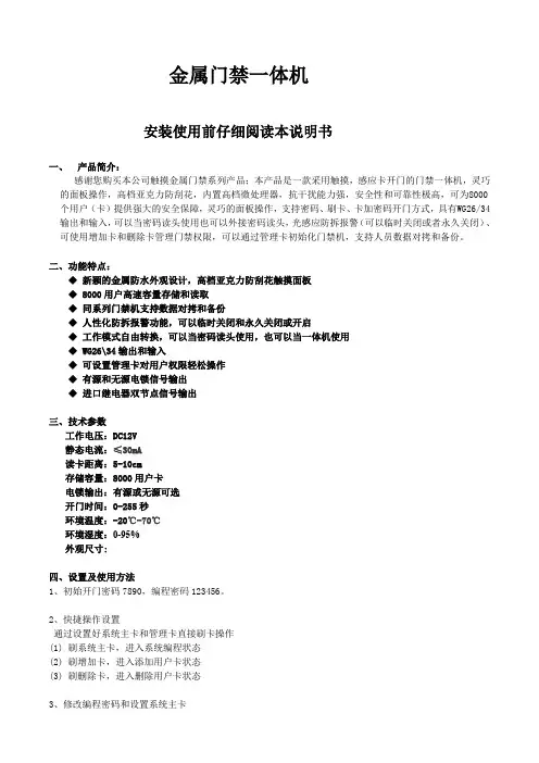
金属门禁一体机安装使用前仔细阅读本说明书一、产品简介:感谢您购买本公司触摸金属门禁系列产品;本产品是一款采用触摸,感应卡开门的门禁一体机,灵巧的面板操作,高档亚克力防刮花,内置高档微处理器,抗干扰能力强,安全性和可靠性极高,可为8000个用户(卡)提供强大的安全保障,灵巧的面板操作,支持密码、刷卡、卡加密码开门方式,具有WG26/34输出和输入,可以当密码读头使用也可以外接密码读头,光感应防拆报警(可以临时关闭或者永久关闭)、可使用增加卡和删除卡管理门禁权限,可以通过管理卡初始化门禁机,支持人员数据对拷和备份。
二、功能特点:◆新颖的金属防水外观设计,高档亚克力防刮花触摸面板◆ 8000用户高速容量存储和读取◆同系列门禁机支持数据对拷和备份◆人性化防拆报警功能,可以临时关闭和永久关闭或开启◆工作模式自由转换,可以当密码读头使用,也可以当一体机使用◆ WG26\34输出和输入◆可设置管理卡对用户权限轻松操作◆有源和无源电锁信号输出◆进口继电器双节点信号输出三、技术参数工作电压:DC12V静态电流:≤30mA读卡距离:5-10cm存储容量:8000用户卡电锁输出:有源或无源可选开门时间:0-255秒环境温度:-20℃-70℃环境湿度:0-95%外观尺寸:四、设置及使用方法1、初始开门密码7890,编程密码123456。
2、快捷操作设置通过设置好系统主卡和管理卡直接刷卡操作(1) 刷系统主卡,进入系统编程状态(2) 刷增加卡,进入添加用户卡状态(3) 刷删除卡,进入删除用户卡状态3、修改编程密码和设置系统主卡(1)按注:蜂鸣器响一声操作成功(密码长度为1-8位)。
(2)按注:刷卡蜂鸣器响一声表示主卡设置成功。
4、添加卡型用户按注:用户编码为任意4位,连续读卡编码自动加1。
5、添加密码型用户按注:4位用户编号(例如1就输入0001),用户密码(0-8位)蜂鸣器鸣响一声,表示添加密码型用户操作成功,继续输入用户编码可连续添加密码型用户(注:一个用户编号只能添加一个用户密码或一张卡,不能同时使用)。

EM100 网络模组(EM100SK Starter Kit) Tibbo TECHNOLOGY技术手册*Tib b oNetModuleTIBBO TECH. INC. TAIWANMODEL NO: EM100PART NO: EM100-00S/N: A 0801 0601请注册获取升级信息Version: 2.1aTibbo Technology, Inc. 2001, 2002欢迎参看Tibbo产品永续升级我们的每一产品都处于不断增强功能状态根据客户的需求我们正不断的加强EM100模块的功能您手上的用户手册可能已经过时请访问我们的网站查找最新硬件软件及文档您还可订阅我们的定期电子邮件获取最新产品信息EM100可以定做成不同形式假如您有其他想法请让我们知道本手册服务对象本用户手册为程序开发和系统管理提供详细的EM100功能介绍和编程信息我们的连接手册为装有EM100模块和使用Tibbo设备服务器工具包软件包括虚拟串口设备驱动程序的设备提供安装和使用信息本手册的服务对象为熟悉以太网和TCP/IP网络的专业人员您的固件要升级么本手册描述运行V2.2x固件的EM100模块的功能请先更新您的EM100到新版本阅读固件下载模式并遵循升级EM100的具体步骤寻求进一步的帮助如果您找不到解决问题的方法请给我们发来e-mail:技术问题support@您的建议feedback@购买需求sales@其它需求info@怎样打印这本手册本手册分为两种形式屏幕和打印您可在屏幕上直接阅读本手册EM100技术手册也可使用以上打印版EM100技术手册打印本手册打印版在A4纸上分为两面目录1. 介绍1.1. 什么是EM1001.2. 使用EM100的三种基本方法2. 控制操作模式和信号2.1. EM100连接与控制2.2. 操作模式2.3. LED信号状态总介3. 普通模式下的操作3.1. 简介3.2. Slave 和 Master 路径模式3.3. 串口>以太网数据路线3.4. 缓冲器相关问题4. EM100编程4.1. 简介4.2. 串口编程模式4.3. 网络编程5. 有效命令和回应5.1. 命令表5.2. 回应码列表5.3. 具体命令描述6. 有效设置6.1. 设置组列表6.2. 具体设置描述7. 有效参数7.1. 参数列表7.2. 具体参数描述8. 硬件下载模式8.1. 下载新硬件文档8.2. 初始化EM1008.3. 下载中可能出现的问题和LED信号9. I/O连接器针口分布和线材9.1. EM100 I/O连接器针口分布9.2. RS232线材9.3. 以太网线材10. 产品类别包装和订购信息10.1 产品类别和包装信息10.2 订购信息1. 简介1.1. 什么是EM100?Em100是一个网络模块 其主要功能是将所有设备连接到网络使用EM100你可以为任何带有RS232界面的串口设备增加一个网络接口你可以通过局域网上的电脑或其他设备与EM100通讯如果您的局域网直接与互连网相连 您还可以从世界上任何一个地方控制您的串口设备1.2. 与EM100通讯的三种基本方法如果您使用已有的电脑软件来控制串口设备那么您可以使用EM100将该设备连接到网络然后在电脑上使用虚拟串口驱动程序(VSPD)与它进行通讯该驱动程序创建的虚拟串口为逻辑COM口和标准的COM 口运行一样 但实际上它使用TCP/IP 网络传输数据到EM100或串口设备 使用VSPD 您可以继续使用原来的电脑软件不需要进行修改如果您正为你的串口设备创建新的电脑软件 那么您可以直接与EM100通讯不需VSPD . EM100传输数据时 使用工业标准的UDP/IP 和TCP/IP 通讯协议大多数软件开发包 如Microsoft 的Visual Basic, 都会为设备和EM100的数据交换提供一个简单的方法请阅读手册使用VB 与EM100/EM100通讯您还可以在网络上创建一个虚拟连接在串口设备端使用EM100 在另一端使用EM100串口设备服务器EM100端的串口必须与串口设备的串口相同2. 控制 操作模式 和信号2.1. EM100 I/O 针口分布Fig. 1. EM100 pin assignmentEthernet port pinsTX+ Output Positive line of the differential output signal pair TX- Output Negative line of the differential output signal pair RX+ Input Positive line of the differential input signal pair RX- Input Negative line of the differential input signal pairSerial port pinsTX Output Serial transmit line RXInput Serial receive lineRTS/DIROutputFull-duplex mode: request to send, Half-duplex Mode: data direction controlCTS/SEL InputClear to Send line, also full-duplex/half-duplex mode selection lineLED control pinsSG Output, 10mA max. Green Status LED control lineSR Output, 10mA max. Red Status LED control lineEG Output, 10mA max. Green Ethernet LED control lineER/WS Output, 10mA max. Red Ethernet LED control line, also watchdog strobe lineGeneral-purpose I/O pinsP0 Input/Output Remotely controlled (through Parameter command) input/outputP1 Input/Output Remotely controlled (through Parameter command) input/outputP2 Input Remotely controlled (through Parameter command) inputP3 Input/Output Remotely controlled (through Parameter command) input/outputEM100 control pinsRST Input Reset, active high (10us min. pulse length)MD Input Mode selection pin (see Operating modes and mode selection)Power supply pinsVCC +5V nominal +/- 5% (4.75…5.25V) DC power (70mA max)GND Ground2 2 具体针口描述网络接口针口分布EM100直接与RJ45 10Base T 以太网相连在开发板上有标准的磁循环为以太网提供一个透明的界面在使用PCB开发板时, 要遵守开发板布置规定串口针口串口包括四个界面线可以在全双工和半双工模式下运行在全双工模式下 EM100支持RX, TX, RTS和CTS信号在半双工模式下 EM100提供RX, TX和DIR信号 DIR针口控制数据方向EM100 串口界面的引角都为CMOS标准active low. 在无数据传输时TX和RX线为高start bit 为低 stop bit 为高 CTS和RTS信号为高时表示不能传输数据为低时表示可以传输数据EM100的串口线可以和大多数主控制器和处理器串口针口相连还可以和RS232驱动IC相连使用全双工操作模式或者和RS485驱动器相连使用半双工操作模式全双工和半双工操作模式可以通过串口界面设置进行选择或者在硬件中使用CTS/SEL 和ER/WS针口请阅读全双工半双工串口传输模式LED控制线EM100可以驱动四种LED.与SG和SR线相连的绿色和红色LED会显示EM100的操作模式和出现的错误信息请阅读LED信号总介与EG和WS线相连的绿色和红色LED显示以太网口的操作情况通常情况下绿色的LED 不会闪亮只有当EM100收到网络数据包时才会暂时闪亮红色LED通常情况下也不会闪亮只有在网络传输数据发生冲突时才会暂时闪亮所有的LED线都为active low. 所以LED的连接必须按图2所示每个LED都需要一个300Ohm 的电阻EM100的ER/WS线也可以作为监控线和串口传输模式的选择线这与该针口的主要功能并不冲突Fig. 2. Connecting LED control lines to the LEDs普通I/O针口EM100有四组I/O 接口可以控制可监控与之相连的传感器的状态I/O 接口可以通过网络 使用参数命令远程进行设置四组I/O 都可以接受信号 其中三个可以输出信号普通的I/O 针口为open-collector type. 在EM100模组里已经包含一个小型电阻图三为简单的电路图 为监控针口的输入状态 必须将该针口的输出驱动设置为低 否则它的输出驱动会将针口所定为低状态Fig. 3. Simplified circuit diagram of the general-purpose I/O pinsEM100控制针口EM100的两个控制针口为RST 和MD.RST 可以重新设置EM100的内部线路 要进行重新进行设置 要保持该针口状态为高至少10uS. RST 必须接到正确的重新设置线路 否则EM100将不能正常运作MD 针口用于选择EM100的操作模式 电源接口EM100需要5VDC(+/-5%)电源23 操作模式和模式的选择 EM100有三种操作模式普通模式 打开电源启动软件 或者另外安装硬件都可以进入普通模式 MD 线不能为低 在该模式下EM100进行网络与串口间的数据传输 在普通模式EM100的网络编程和数据传输可同时进行串口编程模式将MD 线设为低至少100ms, 或者当EM100 在普通模式下时发送escapesequence 到EM100的串口 这时就进入串口编程模式该模式用于从串口设置EM100的功能参数设置硬件下载模式 将MD线设置为低 打开EM100电源重新启动或者从重新设置状态下退出EM100就进入固件下载模式该模式用于下载新固件文档到EM100.T 1Max1s“No reaction zone”- time it takes the EM100 to enter the Normal Mode of operation after the powerup, software restart, or hardware resetT 2Min 20ms MD holding time to enter theSerial Programming Mode T 3Min 1msMD holding time to enter the Firmware Download ModeFig.4. Using MD line to change the operating mode2.4全双工半双工串口传输模式EM100可以选择全双工和半双工串口传输模式通过串口界面和CTS/SEL 和ER/WS 针口进行模式的选择设置串口界面为自动Em100根据硬件配置情况选择全双工和半双工传输模式当CTX/SEL 与ER/WS 相连时 EM100选择半双工模式当CTX/SEL 不与ER/WS 相连时 EM100选择全双工模式当设置串口界面为全双工或半双工模式时 无论CTX/SEL 与ER/WS 连接与否 都会根据设置进行界面选择只有在EM100进入普通模式时才会进行串口传输模式的选择2 5 外围设置为保证EM100的正常工作 必须提供可靠的外围设置这里提供几种方法使用外部修复IC 使用一个特殊的修复IC如MAX810可靠修复电源修复IC 要较RC 线路修复稳定因为后者稳定性不好且在brownout 时不能进行修复使用外部修复IC 带监视芯片更好的方法是使用带监视芯片的外部修复ICER/WS 针口可安置一个100Hz 的监视器芯片这与ER/WS 的主要功能并不冲突 因为监视芯片的修复脉冲很短~2uS .使用主微控制器的一个I/O 接口如果将EM100作为主串口设备主CUP(主微控制器)的一个辅助处理器使用 那么主微控制器的一个I/O 接线可以连接到EM100的RST 针口上许多主微控制器如80C51的I/O 针口在修复时缺损值为高所以如果连接该I/O 口与EM100的RST 输出针口那么同时也要对主微控制器进行修复, 且与主微控制器的修复时间相同主微控制器的固件使EM100退出修复状态我们推荐您使用这种方式 因为通过这种方式 主微控制器可以随时修复EM100或改变EM100的操作模式2 6 典型的线路应用Fig. 5. Standalone application circuit单独操作LTC1232重设/监控IC 用于对EM100的重设监控重设strobe 来自ER/WS 信号线有一个按钮与EM100的MD 针口相连 可将EM100置于不同的操作模式下CES/SEL 信号线与ER/WS 信号线相连 可以选择RS485界面TX 和RX 串口界面信号线与MAX485驱动IC 相连 RTS/DIR 控制RS485的数据传输方向以太线直接与RJ45连接口相连可提供LED 的四种状态通常将以太网LED 安装在RJ45连接器旁Fig. 6. Communications coprocessor application circuit通讯处理器EM100由一个主微控制器控制直接控制EM100的RST 和MD 信号线 就可以将EM100置于不同的操作模式之下这样主微控制器就可以编程EM100下载新固件到EM100.四组串口界面直接与主微控制器的I/O 相连以太网信号线直接与RJ45接口相连四组LED 信号线可与LED 相连 也可不与之相连通常将以太网LED 安装在RJ45连接器旁27 机械规格Fig. 7. Mechanical dimensions of the EM100L Max. 46.2mm Length W Max. 28mm Width H Max. 13mmHeight I Min. 4.5mm Pin length m Max. 1mm Lead “flash”d Aver. 40.6mmDistance between pin rows p Aver. 2mm Pin pitch28 版面布置按以下要求进行版面设置EM100应该尽量与RJ45接口靠近 短的直接线应与EM100的TX+, TX-,, RX+相连 RX-信号线与RJ45相连除了TX+, TX- 和RX-信号线周围的区域外其他区域都应布满不要将地线和电源线靠近这些线 按照这些建议可以降低EM100发出的噪音可以使得EM1和FCC/CE 部分的ESD 测试更简单,Fig. 8. Good board layout example2.9 LED 状态总介EM100有四个针口可以驱动以太网和状态LED . 该部分主要描述普通模式和编程模式下LED 信号状态固件下载模式下LED 的信号描述在下载中可能出现的问题和LED 信号中进行描述Entering the Normal Mode Red and Green LEDs blink 3 timesSetting error, cannot enter the Normal modeRed LED is blinking constantly (Initialize the EM100) In the Normal Mode : • Slave Routing Mode• Master Routing Mode• Destination IP-address is notreachable*• Destination IP-address is reachable*Whenbuffer overflow is detectedGreen LED is constantly on Green LED is blinking Green LED is constantly on Red LED blinks momentarily In the Serial Programming mode Green and Red LEDs are blinking(Green-Red-Green...) 在master 路径模式下 EM100不断发送pings 到目的IP 地址如果没有收到回应绿色指示灯会闪亮当目的IP 回应时 绿色指示灯会 持续亮着2.10 EM100SK, Starter KitEM100SK, Starter Kit 包括安装在测试板上的EM100以太网模组 测试板为测试提供一个必要的运行环境测试板包括安装按钮(与EM100的MD 信号线相连)在普通模式下按下按钮迫使EM100进入串口编程模式按住EM100的按钮 同时打开EM100SK 的电源就进入固件下载模式LED 状态显示器与EM100的SG 和SR 信号线相连显示EM100的操作模式/状况请阅读LED 信号状态简介以太网LED 状态显示器与EM100的EG 和ER/WS 信号线相连收到数据包时 绿色指示灯闪亮网络数据发生错误时 红色指示灯闪亮以太网口10BaseT与EM100的TX+, TX-, RX+和RX-相连串口RS232通过RS232的驱动IC 与EM100的RX, TX, RTS/DIR 和CTS/SEL 针口相连电源- 与EM100的5V 电压适配器和测试板上的其他线路相连 使用DC12V, 200mA 电源适配器Reset IC 为EM100进行合理的重新设置Fig. 9. EM100SK Starter Kit3.普通模式下的操作3.1. 一般信息EM100的主要功能就是在以太网和串口设备间传输数据即串口设备的数据通过以太网做双向传输数据的路径经由两个缓冲器的管制每个缓冲器掌管一个路径方向EM100在普通模式下掌控数据路径许多可编程的设置和参数决定EM100在普通模式下的运行方式设置决定EM100的永久性功能这些设置在串口编程模式下经由串口编程到EM100, 或者在网络编程模式下经由网络编程到EM100. 有些设置的功能参数是暂时的这些功能参数能通过网络进行修改更多信息请阅读EM100的编程以太网接口和网络通讯EM100的以太网口为10BaseT和其他网络设备一样 EM100有一个独一无二的以太网MAC 地址并且要给它分配一个有效的网络IP 地址从逻辑上讲 EM100的网络界面有两个接口一个用户定义的数据口EM100和网络上其他工作台之间进行数据交换另一个接口指令接口有一个固定的数值65535(FFFF Hex)经由网络向EM100发送编程命令EM100可使用传输协议设置的UDP/IP或TCP/IP协议和远程设备进行通讯根据路径模式设置 EM100有两种路径模式 slave 或者master( 请阅读Slave和Master路径模式了解更多信息)其他相关网络设置包括目的 IP地址目的数据端口号网关IP 地址掩码和连接超时请阅读可应用设置的完整说明串口EM100的串口支持TX, RX, CTS, 和 RTS 信号波特率可达到115200在普通模式下串口在EM100和串口设备间传输数据在串口编程模式下该串口用于EM100设置的编程决定串口操作的设置包括波特率(150~115200bps),校验(无偶校验或者奇校验), Bits Per Byte (7 或8), 和数据流量控制(无或者 CTS/RTS)每个设置都有一个对应的参数覆盖通讯设置的值请阅读有效设置路径缓冲器网络口与串口之间的数据传输要经由两个独立的255-byte缓冲器这两个缓冲器掌控数据的路径方向缓冲器是必要的因为网络和串口的运行速度和方式不同网络以数据包的形式收发数据例如一组数据而串口以数据线的方式收发数据每个字节间相互独立以下介绍EM100是怎样转换网络数据包和数据线的以太网 串口数据的路径很简单 EM100透过串口按字节发出收到的网络数据包 EM100不分析或过滤从网络至串口方向的数据内容串口 网络路径就是对串口数据进行数据包装较为复杂几组设置决定具体什么样的数据被接收到缓冲器中缓冲器中的数据什么时候形成封包并发出具体信息请阅读串口至以太网数据路线3.2. Slave 和 Master路径模式EM100有两种路径模式Slave模式和Master模式在Slave路径模式下 EM100在收到远程工作台发出的信息前例如由网络向串口传输数据不由串口向网络发送任何数据远程工作台和EM100通讯前EM100串口接受到的串口数据会被删除在slave 模式下 EM100可以和网络上任何与之连接的工作台通讯在Master路径模式下 EM100不用等待远程工作台发出数据而是主动由串口向网络发出数据数据总是发给一个特定的目的地目的IP地址或者EM100的目的数据口同样EM100只从目的IP地址接受数据其他IP向EM100发出的数据都会被删除注意数据发送者的数据口没有得到证实所以数据可以从任何口传出什么情况下使用Slave和Master路径模式使用Slave路径模式将所有只向电脑发送数据的串口设备连网例如考勤钟门禁控制器和其他的硬件终端使用Master路径模式将主动发送数据的串口设备连网这些设备不需要电脑发送命令就向电脑发送数据例如条码扫描仪和其他只发送数据的读卡器当数据在两个方向独立传输从以太网到串口从串口到以太网的时候也要使用Master路径模式比如你正在创建一个网络 Modem” 要求在两个方向同时传输数据slave和Master路径模式的网络设置在Slave路径模式下 EM100只回应网络上的其他工作台当EM100从远程工作台接收数据时会初始化工作台的IP地址和数据端口在从串口向网络发送数据时EM100会回应这个IP地址和数串口编程模式口所以EM100自己的网络IP地址和数据端口要设为Slave路径模式即使在远程工作台和EM100间有路由器也要将EM100设置为Slave 路径模式在Slave路径模式下不需要设置掩码和网关IP.在Master路径模式下EM100可随时向目的远程工作台发送数据即EM100的IP地址和数据端口以及目的IP地址和目的数据端口都需要进行设置如果目的远程工作台和EM100在不同的网络那么还要设置网络掩码和网关IP地址slave和Master路径模式和UDP/IP 及TCP/IP传输协议UDP/IP和TCP/IP传输数据得方式是不同的所以在Slave和Master路径模式下EM100的使用UDP/IP和TCP/IP传输协议也会有差异UDP/IP 及TCP/IP传输协议o Slave路径模式从远程工作台发向EM100串口的UDP数据包都会传向串口由串口向网络发送数据时EM100只向最后一个UDP数据包发送者的IP和数据端口发送数据如果EM100从另外的工作台接受到UDP数据包它就会向新的工作台发送数据在打开电源和EM100收到第一个UDP数据包以前EM100没有IP地址和数据端口所有发送到EM100的数据都会被删除o Master路径模式EM100只接受和发送从远程工作台发出的数据包到串口远程工作台的IP地址必须和目的IP地址相匹配数据源数据端口不一定要与目的数据端口相匹配所以任一端口都可以发送数据EM100由串口向网络发送数据时会将数据发送给目的IP地址和目的数据端口即使EM100接受的数据包来自远程工作台的不同端口它也会将数据传给目的数据端口所以EM100可能从一个端口接受数据而给另一个的端口发送数据TCP/IP传输协议o Slave路径模式在TCP协议下 EM100可以和任何一个工作台建立联系EM100不会主动和远程工作台建立联系即使EM100要由串口向网络发送数据一旦远程工作台和EM100建立联系数据会在两个方向独立传输在联系建立前EM100接受到的串口数据会被删除o Master路径模式 EM100回应或主动与远程工作台建立连接这取决于谁先发送数据—远程工作台或串口设备当远程工作台要求与EM100建立连接时远程工作台的IP地址必须与EM100的目的IP地址相匹配数据源数据端口不一定要与目的数据端口相匹配所以任何一个端口都可以主动要求建立连接当EM100要求与远程工作台建立连接时它会试图与目的IP地址和目的数据端口建立连接连接建立后数据可在两个方向独立传输与使用UDP/IP通讯协议不同的是 EM100不会从一个数据口接收数据而向另外一个数据口传输数据一旦建立TCP/IP连接两面就可以使用单一数据口进行数据交换一对多连接在实际的运用中可能会有几台电脑通过EM100与一个串口设备通讯或者几台串口设备每一个都经由一个EM100与网络连接与一台电脑了连接几台电脑对一个串口设备的例子例如一台终端设备或感应器可以向网络上的许多电脑传输数据几台串口设备对一台电脑的情况例如几台条码仪要向网络上的一台电脑传输数据几台电脑对一个串口设备的操作要求EM100处于slave路径模式在该模式下EM100会向任何一个信息发送者回应所以任何一个工作台都可以和连有EM100的串口设备通讯O当几个不同的工作台向同一个EM100/串口设备索取数据时不能使用UDP/IP通讯协议否则串口端会混淆数据 EM100也不能给每个工作台回复正确的命令o 在一台电脑与EM100建立联系后即可使用TCP/IP通讯协议在该电脑断开与EM100的连接前其他电脑不能与这个EM100通讯为防止一个电脑无限期地与一个EM100通讯连接超时设置会设置EM100的连接时间在任何方向都没有数据传输时会在设置时间内断开连接多台串口设备对一台电脑时要求EM100处于Master路径模式下在这种模式下 EM100在由串口向网络发送数据时会将数据发送到目的IP地址和目的数据端口很多EM100可以同时给一个目的IP发送数据o 在这种情况下可以使用UDP/IP通讯协议但必须确定串口设备发出的串口数据为单一的UDP数据包如果使用多个UDP数据包传输数据或者几个EM100同时传输数据可能会出现数据混淆使用UDP/IP通讯协议的好处在于在接收端只要有一个listening socket就可以从所有数据源获取信息除非需要区别信息源EM100的几个设置决定串口数据怎样被组装成网络数据包所以您可以确保串口设备传出的数据不会被包装成几个数据包请阅读串口至网络数据路径o TCP/IP通讯协议使用安全但在接收端必须有一个单独的socket以便数据源发送数据3.3.串口到网络数据路线EM100会选择什么样的串口数据进入串口至网络缓冲器这些数据怎样组成网络数据包以及其发送时间串口数据EM100将所收到的串口数据作为数据包处理这里的数据包并不仅仅是有结构的串口数据还可以是随意的串口数据线作为一个连续的无限制的串口数据包串口数据包在开始字元被侦测时开始在终止字元被侦测时结束在终止字元被侦测到时 EM100开始记录串口数据到串口至网络缓冲器开始字元打开串口数据包当终止字元被侦测时EM100停止记录数据到缓冲器并经由网络发出缓冲器中的数据所以终止字元结束串口数据包在数据包之间的数据例如终止字元和起始字元之间的数据会被删除除起始字元和终止字元外还有break字元当break字元被侦测时EM100不会关闭串口数据包它会继续接收数据到串口至网络缓冲器但会经由网络口传输数据Break字元可以将大的串口数据包进行再切分开始字元以任一字元开始这一设置决定EM100会把任何首先进入串口的字元做为起始字元或者是需要一个特定的开始字元打开串口数据包当设置以任一字元开始 EM100会将上一数据包结束处的下一字元作为新数据包的开始字元开启一个新的数据包当不设置以任一字元开始时 EM100只能用预先设置的特定开始字元作为下一数据包的开始可以设置三个不同的开始字元数据包被开启后再发现的开始字元作为普通字元处理不再重新开始一个数据包终止字元可设置三种不同的终止字元结束串口数据包一旦终止字元被侦测 EM100就会结束一个串口数据包并经由网络口发送串口至网络缓冲器中的数据在下一开始字元前的数据都会被忽略使用开始字元和终止字元就意味着在数据包的内部不能再有和开始字元和终止字元相同的字元有一些通讯协议具有检测功能或者其他的数据确认系统该检测功能可能会take any value并且有时还会与终止字元的ASCII码相匹配为了避免可能出现的冲突有些通讯协议将检测字元放在终止字元的后面EM100为每个终止字元设置了邮寄字元数例如为终止字元数设置邮寄字元数为2那么EM100会为当前的串口数据包接收2个字节的数据终止字元本身除外Break字元最大字元长度设置决定串口至网络缓冲器中的最多字元数32-255一旦达到设置的最大字元数EM100就会经由网络口发送缓冲器中的数据该设置只在使用UDP/IP通讯协议时起作用因为TCP/IP通讯协议自己会决定适合在网络上传输的数据包大小最大字元间滞延决定串口接收的两个连续的串口字元间的最长时间长度可设为10ms--2.55 sec一旦超过了这个时间设置 EM100就会经由网络发送串口至网络缓冲器中的数据将最大字元间滞延设为0就可以不执行这个功能缺损开始/终止/Break设置在缺损状态下初始化以后 EM100可以处理没有结构的任意数据线为做到这一点可以设置以任意字元开始没有终止字元最大字元间滞延为10ms最大数据长度为255字节只适用于UDP/IP传输协议这样首先接收到串口中的字元就作为串口数据包的开始字元没有结尾一旦串口缓冲器中的数据量达到极限或者在传输过程中出现断裂 EM100就会组合所有接收到的串口数据并发送实践表明这种方法不仅适用于任意数据线并且适用于有结构的数据假如与EM100相连的硬件终端使用命令回应式通讯协议与电脑通讯在这种情况下终端每回应电脑一次就会等待下一命令这会在接收到EM100的串口缓冲器中产生一个间隔在10ms间隔后EM100会重新向电脑发送回应3.4. 缓冲器相关问题在使用EM100时注意保持网络至串口和串口至网络缓冲器的畅通缓冲器堵塞是由于EM100两边网络和串口接收和传输的速度不同当出现堵塞现象时红色指示灯会闪亮同时如果EM100输出串口数据的速度太快与之相连的串口设备内的接收缓冲器可能会堵塞网络至串口缓冲器o UDP/IP通讯协议网络至串口的缓冲器很容易堵塞因为网络比串口传输的速度要快很多UDP/IP内部不能预防缓冲器堵塞所以不适用于发送连续的数据只适合于发送适应缓冲器的短数据o TCP/IP通讯协议可以防止缓冲器堵塞你可以发送任何大小的数据串口至网络缓冲器防止缓冲器堵塞的唯一方法就是启动EM100的RTS/CTS数据流量控制设置这样一。

S100EM金属密码门禁一体机安装利用前认真阅读本说明书1 产品简介:本产品为非接触式感应卡金属密码门禁一体机,依照型号不同别离支持EM、HID、MIFARE三种感应卡,是目前最先进的单门门禁操纵器之一。
它采纳独特的金属外壳设计,灵巧的键盘面板操作,内置高级微处置器,抗干扰能力强,平安性和靠得住性极高,可为2000个用户提供壮大的平安保障。
它具有超低功耗、夜光键盘、独立密码、韦根输出、输出短路爱惜、门磁报警、防拆报警、开门按钮、门铃接口、平安级别设置等壮大功能,利用超级方便,可普遍应用于家庭、办公室、住宅小区及其它公开场合。
2 功能特点:超低功耗:待机电流小于30mA。
夜光键盘:夜晚也能操作键盘。
用户容量大:支持2000个用户。
独立密码:可利用与卡无关的密码开门。
用户修改密码:用户可自行修改开门密码。
搜索速度快:刷卡至开门时刻小于。
输出短路爱惜:电锁或报警输出短路时100μS内自动关闭输出。
韦根输出:带有维根输出接口,能输出Wg26卡号或Wg34按键号。
可用键盘删除卡号:卡丢失后可用键盘删除该卡,完全排除平安隐患。
防拆报警:非法拆机后内置蜂鸣器发出报警音。
有门铃按键和接口:按键与电路隔离,可外接任何门铃。
3技术参数工作电压:DC12V静态电流:≤30mA读卡距离:3~6cm存储容量:2000个用户环境温度:-35℃~60℃环境湿度:10%~90%电锁输出:≤3A报警输出:≤20A输出短路爱惜时刻:≤100μS开门时刻:0~99秒(可调)外形尺寸:120 *80*25mm4治理员操作恢复出厂设置:机械断开电源,按下#键不松开手,然后通电,机械“嘀嘀”两声后松手。
即为机械初始化成功。
注:恢复出厂设置可不能删除用户资料。
进入治理员操作状态:按。
治理员默许密码为999999。
修改治理员密码:按注:治理员密码为6~8位任意数字,请妥帖保管好。
添加用户:4.2.1 持续增加卡:按,…。
4.2.2 指定卡号增加:按,…。
slneeem100变频器参数说明书
产品参数:
产品名称:SlneeEM100变频器
产品分类:EM变频器
产品系列:迷你型变频器
参数说明:
F00,01=0 V/F开环控制:
可运用于一拖多和对快速性、低频转矩、转速精度要求不高的调速场合。
F00.01=1无矢量控制:
此驱动控制方式下,对输出电流全程实时闭环控制,通过电流反馈量,变频器会对输出量进行开环滑差补偿和定子电阻压降补偿,此两种补偿的补偿量由功能码F05.10和F05.11决定,也可以通过调整F05.12(励磁提升增益)对输出频率和转矩进行微调。
F00.02个位=0本机键盘:
由键盘RUN、STOP/RESET、JOG/键控制变频器的启动与停车。
在无故障情况下,按JOG/+-键进入点动运行状态:按RUN鍵进入运行状态。
RUN键上的绿色LED灯常亮表示变频器处于运行状态,闪烁表示变频器处于停车减速状态。
F00.02个位=1端子:
由多功能输入端子RUN、F/R、FJOG、RJOG等进行命令控制。
具
体的控制逻辑参考F00.02十位说明。
F00.02个位=2通讯控制:
运行命令由上位机通过通讯方式给出。
前言感谢您选用深圳市正弦电气股份有限公司研制的EM100系列变频器。
资料编号:31010019资料版本:109发布时间:2017-01EM100系列变频器是正弦电气研制推出的高性能、简易型交流电机驱动器。
稳定、可靠、易于使用是其重要特征。
本手册将为你提供EM100系列变频器的安装、配线、功能参数、日常维护、故障诊断等相关特性、及其操作方法与注意事项。
为了确保能够正确使用本系列变频器,充分发挥产品的卓越性能并确保使用者和设备的安全,在使用EM100系列变频器之前,请您务必详细阅读本手册。
不正确的使用可能会造成变频器运行异常、发生故障,甚至发生设备损坏、人身伤亡等事故!本使用手册为随机发送的附件,请妥善保管。
变频器首次与电机连接时,请您设定电机铭牌参数:额定频率、额定功率、额定电压、额定电流、额定转速、额定功率因数及电机接法。
由于我们始终致力于产品和产品资料的不断完善,因此,本公司提供的资料如有变动,恕不另行通知。
最新变动和更多内容,请访问 目录第一章安全注意事项 (3)1.1安全事项 (3)1.2注意事项 (6)第二章产品信息 (7)2.1产品确认 (7)2.2命名规则及铭牌 (7)2.3变频器型号 (8)2.4技术规范 (8)2.5产品部件说明 (10)2.6产品外形和安装尺寸 (11)第三章产品安装 (13)3.1机械安装 (13)3.2电气接线 (22)第四章操作与显示 (37)4.1操作与显示界面介绍 (37)4.2功能码查看及修改方法说明 (38)第五章功能参数表 (42)5.1功能代码表说明 (42)5.2功能参数表 (42)第六章参数说明 (54)第七章故障诊断及对策 (95)第八章电磁兼容性指导 (99)第九章保养和维护 (102)9.1变频器的日常保养与维护 (102)9.2变频器的保修说明 (103)附录A:EM100 MODBUS通讯协议 (104)附录B:选配件说明 (110)附录C:客户常见问题及处理措施 (111)第一章安全注意事项安全定义:在本手册中,安全注意事项分以下两类;危险:由于没有按要求操作造成的危险,可能导致重伤,甚至死亡的情况。
目录第一章概述 (2)第二章安装确认 (2)2.1产品确认 (2)2.2控制端子确认 (2)2.3应用模式确认 (3)第三章运行参数 (4)3.1收放卷专用功能参数 (4)3.2收放卷模式其它相关功能参数 (14)3.3伸线模式(F00.24=4)预置的参数 (15)第四章调试说明 (16)4.1放卷调试说明 (16)4.2拉丝机调试说明 (17)第五章电气原理图 (21)5.1动力放卷电气原理图 (21)5.2动力放卷电气原理图说明 (21)5.3双变频拉丝机电气原理图 (22)5.4双变频拉丝机电气原理图说明 (24)第一章概述1.1 本手册需要与《EM100变频器用户手册》配合使用。
本手册仅介绍与闭环张力控制有关的部分,其它基本功能请参照《EM100变频器用户手册》。
1.2 当应用模式被选择为无效时,变频器的功能与EM100完全相同。
1.3 收放卷功能支持5种应用模式:●放卷模式:此模式实现放卷功能,除需要选择放卷模式并恢复出厂值外无需配置其它任何参数,正确接线即可正常运行。
●收卷模式1:此模式实现简单收卷功能,无需任何机械参数,正确接线一般即可运行。
●收卷模式2:此模式可以自动计算卷径,实现更好的张力控制效果,但需要输入相关的机械参数。
●伸线模式:自动配置伸线相关参数,用于伸线控制。
●收卷模式3:此模式无需获取主机的速度,但需要在尚未能拉出线前即启动收卷变频器。
第二章安装确认2.1 产品确认2.1.1请查看变频器铭牌,确认产品是否具有收放卷功能。
型号中带有尾缀“CD”的,即表明此产品具有收放卷功能例:产品型号为EM100-2R2-3B-CD 即表明该产品有收放卷功能2.1.2上电后,请查看是否有F00.24功能代码,如有即可确认产品具有收放卷功能。
2.2 控制端子确认RJ45图1 EM100系列变频器控制端子示意图2.2.1如果张力反馈信号为电压,请将拨码开关S2置于上方即“V”位置。
2.2.2如果张力反馈信号为电流,请将拨码开关S2置于下方即“I”位置。
正弦变频器 EM100 手册正文:一、概述正弦变频器 EM100 是一种用于电机控制的设备,通过将直流电源转换为交流电源,实现对电机速度的精确控制。
本手册旨在为用户提供关于 EM100 正弦变频器的详细说明和操作指南。
二、产品特点2.1 高精度控制:EM100 正弦变频器采用先进的控制算法,能够实现对电机的高精度控制,达到千分之一的速度调节范围。
2.2 广泛应用:EM100 正弦变频器适用于各种交流电机控制场景,可广泛应用于工业生产、机械设备、自动化系统等领域。
2.3 用户友好界面:EM100 正弦变频器配备了直观易用的操作界面,可以方便地进行参数设置和监控。
三、安装和接线3.1 安装步骤:1)将 EM100 正弦变频器安装在合适的位置,确保周围环境通风良好。
2)根据变频器的输入和输出要求,正确连接电源和电机。
3)固定好变频器和接线,确保其稳定可靠。
四、参数设置4.1 基本参数设置:1)运行频率:根据实际需求设置电机的运行频率,范围为0-200Hz。
2)加速时间和减速时间:设置电机启动和停止时的加速和减速时间,以避免过载和机械冲击。
3)电流限制:根据电机的额定电流设置电流限制,以保护电机和变频器。
4)其他参数:根据实际需求设置其他参数,如速度曲线、过载保护等。
五、故障排除5.1 常见故障及解决方法:1)变频器无法启动:- 检查电源是否接通。
- 检查电机是否正常。
- 检查参数设置是否正确。
2)电机运行不稳定:- 检查电源电压是否稳定。
- 检查参数设置是否合理。
- 检查电机是否存在故障。
六、附件本文档附带以下附件供参考:1)EM100 正弦变频器技术参数表;2)EM100 正弦变频器安装图纸。
七、法律名词及注释1)正弦变频器:一种设备,用于将直流电源转换为交流电源,实现对电机速度的精确控制。
2)交流电机:一种电机,根据交流电源的频率改变转子的转速,广泛应用于各种机械设备。
Safety Manual for Sendyne SIM100 Isolation Monitors This document describes how to use the Sendyne SIM100 family of isolation monitors in safety-related systems.ContentsSafety Manual for Sendyne SIM100 Isolation Monitor 1 Introduction (2)Sendyne SIM100 overview (2)Safety functions and diagnostics overview (3)Target applications (4)Assumptions (6)Custom development (6)Safety documentation (6)Audits and certification (6)Device operating states (6)Product lifecycle support ....................................................................................................... E rror! Bookmark not defined. Appendix (7)Proper connection to the target system (8)Revision history (10)List of figuresFigure 1: SIM100 functional diagram (3)Figure 2: The boundary diagram of SIM100 as SEooC in EV implementations (4)Figure 3: The boundary diagram of SIM100 as SEooC in EV implementations (5)Figure 4: Operating states of the SIM100 (7)Figure 5: Proper connection to IT power system terminals (8)Figure 6: Proper connection at two distinct point to the chassis (8)Figure 7: Presence of Y-capacitors is a requirement for proper function of the SIM100. The capacitors should be connected directly to the power lines. Connecting them on the SIM100 board instead would impair the ability of the monitor to detect disconnection from the monitored IT power lines. (9)IntroductionThe system and equipment manufacturer or designer intending to use this product is responsible to ensure that their system incorporating Sendyne’s SIM100 meet all applicable safety, regulatory and system level performance requirements. All information presented in this document is for reference only. Users understand and agree that their use of SIM100 in safety-critical applications is entirely at their risk, and that user (as buyer) agrees to defend, indemnify, and hold harmless Sendyne from any and all damages, claims, suits, or expense resulting from such use.This safety manual provides information to assist system developers in creating safety-related systems incorporating the Sendyne SIM100 isolation monitoring device. This document contains: •Overview of the SIM100 architecture•Overview of the safety architecture for management of hardware failures•Assumptions of UseSendyne assumes that the user of this document has a general familiarity of the SIM100. This document is intended to be used in conjunction with the relevant datasheet and application notes.Sendyne SIM100 overviewThe SIM100 is an electrically isolated device that when connected properly to an idle or active high voltage IT power system (floating ground) can estimate the resistive and capacitive paths between each power rail of the IT system and a third reference point. The SIM100 can communicate through CAN bus (250 or 500 kbits/s) and when interrogated by a host it can provide estimates on the values of each resistive and capacitive path. The SIM100, based on information programmed by the host for the designed maximum voltage of the IT power system, will calculate a value for the minimum resistance path between the two IT power system rails and the third voltage reference point, expressed in Ohms/Volt (max designed voltage). In addition, it will estimate the total energy that can be potentially stored in the IT power system capacitances. If the CAN bus host fails to provide information on the maximum IT power system voltage, the SIM100 will calculate these values based on the maximum voltage observed during its operation.The SIM100 power input accepts any supply voltage between 4.8 V and 53 V. The input voltage is pre-regulated and then stepped down through a DC/DC converter feeding through galvanically isolated inputs the +5 V IC supply and the 12.5 V excitation voltage source supply.The SIM100 safety architecture includes a watchdog timer, CRC check on internal non-volatile program memory, diagnostics for proper connections of chassis and IT power system terminals, monitoring of the unregulated power supply voltage level for the main IC before local voltage regulator (LDO), environment temperature monitoring and excitation pulse voltage monitoring. In addition, the SIM100 safety architecturemonitors the voltage divider values for chassis, positive and negative voltage connections and provides a visual heartbeat signal indicating proper IC operation.All estimates of isolation resistances and capacitances are submitted along with an uncertainty percentage value. This value defines the interval within which the actual value lies with a probability of 95%.Figure 1: SIM100 functional diagramSafety functions and diagnostics overviewThe SIM100 is intended for use in automotive and industrial safety-relevant applications. All components used are automotive rated.HardwareThe following list of monitoring functions are implemented in the SIM100.•V U, SUPPLY monitor•V X, SUPPLY monitor•V X1 connection monitor•V X2 connection monitor•V X1 voltage divider ratio monitor•V X2 voltage divider ratio monitor•V CH1 and V CH2 connections monitor•V X_CH voltage divider ratio monitor•V X_CH Excitation Voltage Source voltage value monitor•V X_THR environment temperature monitorUpon diagnosing a hardware error, the SIM100 will set the appropriate flags and enter a SAFE state. SoftwareOn the RESET state the SIM100 performs CRC check on the non-volatile memory. During active operation a watchdog timer ensures proper program flow. In addition, every estimate on the isolation state of the monitored IT power system is accompanied by the uncertainty value of this estimate.Target applicationsThe Sendyne SIM100 has been designed to be used as an element for the isolation safety system in applications such as:•Automotive•Charging stations•Industrial high voltage ungrounded systemsFig. 2 and Fig. 3 show the boundary diagram for the SIM100 as a SEooC (Safety Element out of Context) in two different applications.Figure 2: The boundary diagram of SIM100 as SEooC in EV implementationsFigure 3: The boundary diagram of SIM100 as SEooC in EV implementationsAssumptionsThe following table lists the assumptions made for safe employment of the SIM100 is a safety critical system. ID Type Assumed RequirementAR01 Assumed Requirement The SEooC is defined as the SIM100 playing a role as an isolation monitoringelement as shown in Fig. 2 and Fig. 3AR02 Assumed Requirement Thermal environment is between -40 o C and +105 o C (Temperature range islimited by connector thermal specifications.AR03 Assumed Requirement The IT Power System voltage monitored by the SIM100 will vary between 15 Vand its maximum operational voltage – see SIM100 datasheetAR04 Assumed Requirement The IT Power System is connected to chassis through Y-Capacitors of at least100 nF on each side of the power supplyAR05 Assumed Requirement The SIM100 is supplied with proper power according to the specifications of therelevant SIM100 datasheetAR06 Assumed Requirement No other isolation monitoring device is active in the monitored system Table 1: Assumed Requirements for SIM100 as a SEooCCustom developmentThe SIM100 has been developed as a safety element out of context and is offered as a commercial off-the-shelf product. Safety requirements used were based on Sendyne’s understanding of the safety requirements of potential applications.Safety documentationVerification and validation of the SIM100 safety features was performed through testing and computer simulation. Results of SIM100 testing following guidelines of different standards as well as the model used for SIM100 safety function testing can be made available at Sendyne’s discretion under an NDA (non-disclosure agreement)Audits and certificationSendyne has no plans to perform an external audit of the SIM100 to ISO 26262 or other standards. Documentation, including this manual can be made available to support customer system audit and certification. Forward any request for an independent audit to your sales contact.Device operating statesFig. 3 shows an overview of the operating states of SIM100. Refer to the product datasheet and other documentation for details.Figure 4: Operating states of the SIM100AppendixProper connection to the target systemConnection to the IT power systemConnector J3 should connect to the higher potential conductor in the system. J4 should connect to the lower.Figure 5: Proper connection to IT power system terminalsConnection to chassisThe SIM100 should connect through J1 at two separate chassis points. The SIM100 relies on this type of connection to detect proper connection to the chassis. If both leads from J1 are connected to the same point there is a possibility of an undetected disconnection. Such an event will jeopardize the SIM100 safety function.Figure 6: Proper connection at two distinct point to the chassisY-capacitance in un-earthed DC systemsThe Y-capacitances in an IT DC system are the total capacitances that exist between the high voltage conductors (+/-) and the chassis (or protected earth) of that system. The values in a given system are the total of the parasitic capacitances associated with the particular system design, including loads, conductor routing, etc, as well as the physical Y-capacitor components designed into such systems for EMI and converter noise suppression.Presence of Y-capacitorsThe SIM100 relies on the presence of the ubiquitous Y-capacitors in the application system to perform its safety function, namely, to diagnose its proper connections to the HV system. Absence of Y-capacitors with a minimum value of 100 nF will flag a connection error and lead the SIM100 into the SAFE state.Figure 7: Presence of Y-capacitors is a requirement for proper function of the SIM100. The capacitors should be connected directly to the power lines. Connecting them on the SIM100 board instead would impair the ability of themonitor to detect disconnection from the monitored IT power lines.Revision historyDate Revision Changes11/15/2018 0.1 Initial release1/17/2019 0.2 Added image for proper connection of Y capacitors2/11/2019 0.2a Added image for isolation monitoring in charging stations. Added assumedrequirement for no other active isolation monitoring device in the IT powersystem3/10/23 0.3 Revised to encompass SIM100 familyTable 2: Document revision historyInformation contained in this publication regarding device applications and the like, is provided only for your convenience and may be superseded by updates. It is your responsibility to ensure that your application meets with your specifications.SENDYNE SENSATA TECHNOLOGIES MAKES NO REPRESENTATIONS OR WARRANTIES OF ANY KIND WHETHER EXPRESSED OR IMPLIED, WRITTEN OR ORAL, STATUTORY OR OTHERWISE, RELATED TO THE INFORMATION, INCLUDING BUT NOT LIMITED TO ITS CONDITION, QUALITY, PERFORMANCE, MERCHANTABILITY OR FITNESS FOR PURPOSE. Sendyne disclaims all liability arising from this in-formation and its use. Use of Sendyne devices in life support and/or safety applications is entirely at the buyer’s risk, and the buyer agrees to defend, indemni-fy and hold harmless Sendyne from any and all damages, claims, suits, or expenses resulting from such use. No licenses are conveyed, implicitly or otherwise, under any Sendyne intellectual property rights.。
EM100简易门禁一体机操作手册一、 产品特性:①工作电压:DC 12V ②工作电流:≤70mA;③静态电流:≤45mA;④工作温度:-10℃~70℃ ⑤工作湿度:10%~90% ⑥尺寸:117×117×22⑦读卡距离:10~20cm ⑧同时支持三种工作方式:刷卡开门+密码开门;密码开门;⑨用户数量:1000个用户; ;⑩外接读卡器、门磁报警、防撬报警等三项功能要特制二、 接线说明● J2排线BELL+ BELL- +12VDC GND NC COM NO HANDLE STATUS GND 门铃开关电源正负常闭公共地常开开门按钮门状态公共地● J3排线(可外接普通W26读卡器,要特制)+12VDC GND D0 D1电源正负数据0 数据1● 电锁的接法:三、门禁控制器编程方法● “#”键盘,功能键,进入编程模式A、按“#”字键,POWER(红)灯,OK(绿)灯、MODE(橙)灯齐亮。
B、输入6位系统密码(初始密码000000),蜂鸣器鸣响一声POWER(红)灯、MODE(橙)灯亮,OK(绿)灯熄灭,门禁控制器进入系统编程模式。
注意:(1)一定要先执行:“#”键,功能键,进入编程模式,才能进行后面的操作(2)当执行完下列中的任何一项命令后,不要退出编程模式,可以接着执行下列中的任何一项命令。
● “0”键,加入卡+密码型用户A 、 按“0”字键,MODE (橙)灯亮,POWER (红)灯、OK(绿)灯熄灭。
B 、 输入3位用户号,OK (绿)灯亮,输入号有效。
C 、 输入6位密码,蜂鸣器鸣叫一声,OK (绿)灯闪烁,读取需登录的用户卡,蜂鸣器鸣叫一声,OK (绿)灯灭,MODE (橙)灯和POWER (红)灯亮,用户登录成功,返回设置状态。
注意:“卡+密码”是指用户开门 需要读卡 并正确输入密码 ● “1”键,修改系统密码A 、 按“1”字键,MODE (橙)灯亮,POWER (红)灯、OK (绿)灯熄灭。
前言感谢您选用深圳市正弦电气股份有限公司研制的EM100系列变频器。
资料编号:31010019资料版本:109发布时间:2017-01EM100系列变频器是正弦电气研制推出的高性能、简易型交流电机驱动器。
稳定、可靠、易于使用是其重要特征。
本手册将为你提供EM100系列变频器的安装、配线、功能参数、日常维护、故障诊断等相关特性、及其操作方法与注意事项。
为了确保能够正确使用本系列变频器,充分发挥产品的卓越性能并确保使用者和设备的安全,在使用EM100系列变频器之前,请您务必详细阅读本手册。
不正确的使用可能会造成变频器运行异常、发生故障,甚至发生设备损坏、人身伤亡等事故!本使用手册为随机发送的附件,请妥善保管。
变频器首次与电机连接时,请您设定电机铭牌参数:额定频率、额定功率、额定电压、额定电流、额定转速、额定功率因数及电机接法。
由于我们始终致力于产品和产品资料的不断完善,因此,本公司提供的资料如有变动,恕不另行通知。
最新变动和更多内容,请访问 目录第一章安全注意事项 (3)1.1安全事项 (3)1.2注意事项 (6)第二章产品信息 (7)2.1产品确认 (7)2.2命名规则及铭牌 (7)2.3变频器型号 (8)2.4技术规范 (8)2.5产品部件说明 (10)2.6产品外形和安装尺寸 (11)第三章产品安装 (13)3.1机械安装 (13)3.2电气接线 (22)第四章操作与显示 (37)4.1操作与显示界面介绍 (37)4.2功能码查看及修改方法说明 (38)第五章功能参数表 (42)5.1功能代码表说明 (42)5.2功能参数表 (42)第六章参数说明 (54)第七章故障诊断及对策 (95)第八章电磁兼容性指导 (99)第九章保养和维护 (102)9.1变频器的日常保养与维护 (102)9.2变频器的保修说明 (103)附录A:EM100 MODBUS通讯协议 (104)附录B:选配件说明 (110)附录C:客户常见问题及处理措施 (111)第一章安全注意事项安全定义:在本手册中,安全注意事项分以下两类;危险:由于没有按要求操作造成的危险,可能导致重伤,甚至死亡的情况。
注意:由于没有按要求操作造成的危险,可能导致中度伤害或轻伤,及设备损坏的情况。
请用户在安装、调试和维修本系统时,仔细阅读本章,务必按照本章内容所要求的安全注意事项进行操作,如出现因违规操作而造成的任何伤害和损失均与本公司无关。
1.1安全事项安装前:危险1.开箱时发现包装进水、部件缺少或有部件损坏时,请不要安装!2.外包装标识与实物名称不符时,请不要安装!危险1.搬运时应该轻抬轻放,否则有损害设备的危险!2.有损伤的变频器或缺件的变频器请不要使用,有受伤的危险!3.不要用手触及控制系统的元器件,否则有静电损坏的危险!安装时:危险1.请安装在金属等阻燃的物体上,远离可燃物,否则可能引起火警!2.不可随意拧动设备元件的固定螺栓,特别是带有红色标记的螺栓!注意1.不能让导线头或螺钉掉入变频器中,否则引起变频器损坏!2.请将变频器安装在震动少,避免阳光直射的地方。
3.变频器置于相对密闭柜或空间时,请注意安装位置,保证散热效果。
接线时:危险1.必须遵守本手册的指导,由专业电气工程人员施工,否则会出现意想不到的危险!2.变频器和电源之间必须有断路器隔开,否则可能发生火警!3.接线前请确认电源处于零能量状态,否则有触电的危险!请按照标准对变频器进行正确接地,否则有触电危险!4.接地端子一定要可靠接地,否则有触电和火灾的危险!5.不建议使用双键盘,否则可能会出现意想不到的危险!注意1.绝不能将输入电源连接到变频器的输出端子(U、V、W)上。
注意接线端子的标记,不要接错线!否则引起变频器损坏!2.确保所配线路符合EMC要求及所在区域的安全标准。
所用导线线径请参考首选建议。
否则可能发生事故!3.绝不能将制动电阻直接接于直流母线、端子之间,否则引起火警!4.请用指定力矩的螺丝刀紧固端子,否则有火灾的危险。
5.请勿将移相电容及LC/RC噪声滤波器接入输出回路。
6.请勿将电磁开关、电磁接触器接入输出回路,否则变频器的过电流保护回路动作,严重时,会导致变频器内部损坏。
7.请勿拆卸变频器内部的连接线缆,否则可能导致变频器内部损坏。
上电前:注意1.请确认输入电源的电压等级是否和变频器的额定电压等级一致;电源输入端子(R、S、T)和输出端子(U、V、W)上的接线位置是否正确;并注意检查与变频器相连接的外围电路中是否有短路现象,所连接线路是否紧固,否则引起变频器损坏!2.变频器的任何部分无须进行耐压试验,出厂时产品已作过此项测试。
否则引起事故!危险1.变频器必须盖好盖板后才能上电,否则可能引起触电!2.所有外围配件的接线必须遵守本手册的指导,按照本手册提供电路连接方法正确接线。
否则可能会引起事故!上电后:危险1.不要用湿手触摸变频器及周边电路,否则有触电危险!2.不要触摸变频器的任何输入输出端子,否则有触电危险!3.上电初,变频器自动对外部强电回路进行安全检测,此时,绝不能触摸变频器U、 V、W接线端子或电机接线端子,否则有触电危险!危险1.若需要进行参数辨识,请注意电机旋转中伤人的危险,否则可能引起事故!2.请勿随意更改变频器厂家参数,否则可能造成设备的损害!运行中:危险1.请勿触摸散热风扇、散热器、金属底板及放电电阻以试探温度,否则可能引起灼伤!2.非专业技术人员请勿在运行中检测信号,否则可能引起人身伤害或设备损坏!注意1.变频器运行中,应避免有东西掉入设备中,否则引起设备损坏!2.不要采用接触器通断的方法来控制变频器的启停,否则引起设备损坏!保养时:危险1.请勿带电对设备进行维修及保养,否则有触电危险!2.确认在、两端子间电压低于DC36V时才能对变频器实施保养及维修,以断电后五分钟为准,否则电容上残余电荷对人会造成伤害!3.没有经过专业培训的人员请勿对变频器实施维修及保养,否则造成人身伤害或设备损坏!4.更换变频器后必须进行参数的设置,所有可插拔接口必须在断电情况下插拔!1.2注意事项电机绝缘检查电机在首次使用、长时间放置后的再使用之前及定期检查时,应做电机绝缘检查,防止因电机绕组的绝缘失效而损坏变频器。
绝缘检查时一定要将电机连线从变频器分开,建议采用500V电压型兆欧表,应保证测得绝缘电阻不小于5MΩ。
电机的热保护若选用电机与变频器额定容量不匹配时,特别是变频器额定功率大于电机额定功率时,务必调整变频器内电机保护相关参数值或在电机前加装热继电器以对电机保护。
工频以上运行本变频器可提供0.00Hz~320.00Hz的输出频率。
若客户需在50.00Hz以上运行时,请考虑机械装置的承受力。
关于电机发热及噪声因变频器输出电压是PWM波,含有一定的谐波,因此电机的温升、噪声和振动同工频运行相比会略有增加。
输出侧有压敏器件或改善功率因素的电容的情况变频器输出是PWM波,输出侧若安装有改善功率因素电容或防雷用压敏电阻等,则易引发变频器瞬间过电流甚至损坏变频器,请不要使用。
额定电压值以外的使用不适合在手册所规定的允许工作电压范围之外使用EM100系列变频器,易造成变频器内器件损坏,如果需要,请使用相应的升压或降压装置进行变压处理。
三相输入改成两相输入不可将EM100系列中三相变频器改为两相使用,否则将导致故障或变频器损坏。
雷电冲击保护本系列变频器内装有雷击过电流保护装置,对于感应雷有一定的自我保护能力,对于雷电频发处客户还应在变频器前端加装保护。
海拔高度与降额使用在海拔高度超过1000m的地区,由于空气稀薄造成变频器的散热效果变差,有必要降额使用,此情况请向我公司进行技术咨询。
变频器的报废时注意主回路的电解电容和印制板上电解电容焚烧时可能爆炸,塑胶件焚烧时会产生有毒气体,请按工业垃圾进行处理。
客户常见问题及处理措施EM100变频器上市后,在使用中遇到一些问题,解决方案汇总在附录C。
第二章产品信息2.1产品确认注意受损的变频器及缺少零部件的变频器,切勿安装,否则有受伤的危险。
拿到产品时,请按下表确认。
确认项目确认方法与订购的商品是否一致请确认变频器侧面的铭牌。
是否有受损的地方查看整体外观,检查运输途中是否受损。
螺丝等紧固部分是否有松动必要时,用螺丝刀检查一下。
2.2命名规则及铭牌命名规则产品分类EM:变频器产品系列:100:迷你型变频器适配负载功率:0R4 0.4kW …………2R22.2kW…………EM 100 – 0R7 – 1 BB:内置制动单元无:不含制动单元电压等级:1:单相220V2:三相220V3:三相380V铭牌型号:EM100-0R7-1B额定功率:0.75kW输入电压:AC 220V额定电流:4.8A序列号:深圳市正弦电气股份有限公司2.3 变频器型号表2-1 EM100系列变频器型号额定输入电压型号适用电机功率(kW)额定输出电流(A)单相交流220V EM100-0R4-1B 0.4 2.8 EM100-0R7-1B 0.75 4.8 EM100-1R5-1B 1.5 8.0 EM100-2R2-1B 2.2 10 EM100-4R0-1B 4.0 17三相交流220V EM100-0R4-2B 0.4 2.8 EM100-0R7-2B 0.75 4.8 EM100-1R5-2B 1.5 8.0 EM100-2R2-2B 2.2 10 EM100-4R0-2B 4.0 17 EM100-5R5-2B 5.5 25 EM100-7R5-2B 7.5 32三相交流380V EM100-0R7-3B 0.75 2.8 EM100-1R5-3B 1.5 4.8 EM100-2R2-3B 2.2 6.2 EM100-4R0-3B 4.0 9.2 EM100-5R5-3B 5.5 13 EM100-7R5-3B 7.5 17 EM100-011-3B 11 25 EM100-015-3B 15 322.4 技术规范表2-2 EM100系列变频器技术规范项目项目描述输入EM100-XXX-1B: 单相220V(±20%) 50~60Hz(±5%) EM100-XXX-2B: 三相220V(±20%) 50~60Hz(±5%) EM100-XXX-3B: 三相380V(±20%) 50~60Hz(±5%)输出最大输出电压最大输出电压与输入电源电压相同满载输出电流100%额定电流连续输出过载特性150% 额定电流1分钟,180% 额定电流10秒,200% 额定电流2秒基本控制功能驱动方式V/F、无PG矢量控制速度给定方式模拟量、通讯、多段速预置、键盘运行方式键盘、控制端子(二线控制、三线控制)、RS485 频率控制范围0.00~320.00Hz给定频率分辨率数字方式:0.01Hz 模拟方式:0.10Hz调速范围1:50速度控制精度1%加、减速时间0.01秒~600.00秒电压/频率特性额定输出电压5%~100%可调,基频20.00~320.00Hz可调转矩提升自动转矩提升、固定转矩提升曲线、任意V/F曲线可选启动力矩150%/1Hz输出电压自调整AVR功能有效时,输入电压变化,输出电压保持不变;精度:额定输入电压时±10V电流自动限幅自动限定输出电流,避免频繁过流跳闸直流制动制动时间:0~30秒;制动电流:150%额定电流信号输入源数字、模拟电压、模拟电流、多段速、简易PLC、MODBUS通讯,摆频,PID。