parker派克密封件标准V1
- 格式:pdf
- 大小:1.23 MB
- 文档页数:4
派克汉尼汾公司版权所有未经许可不能摘录,翻印。
保留修改权利2021年6月警告销售条件本样本中产品和/或系统或相关产品出现故障,选型不当或使用不当,均可能导致人身伤亡和财产损失。
本文档以及由派克·汉尼汾公司及其子公司和授权经销商提供的其他资料,为具有技术知识的用户提供进一步研究所需的产品和/或系统选项。
重要的是,用户必须对您的应用进行全面的分析,并对当前产品样本中与产品或系统相关的资料进行评估。
由于工作条件以及产品或系统的多样性,用户必须自行分析和测试,并独自承担一切后果,包括:产品和系统的最终选型以及确保满足应用的所有性能、安全和警告等方面的要求。
派克·汉尼汾及其子公司可能会随时对本样本中的产品,包括但不限于:产品的特性、产品的规格、产品的结构、产品的有效性以及产品的价格作出变更而不另行通知.本样本中的所有产品均由派克·汉尼汾公司及其子公司和援权经销商销售。
与派克签订的任何销售合同均按照派克标准条件和销售条件中规定的条款执行(提供复印件备索)。
本公司的密封件,只能在本公司的文件资料述及的应用参数范围与接触介质、压力、温度和存放时间相一致的情况下才能使用。
在规定的应用参数范围外使用以及错误选用不同的材料都可能导致密封件寿命的缩短以及设备的损坏,甚至更严重的后果(如生命安全,环境污染等)。
样本中所列出的工作压力、温度范围、运动速度是极限值,它们之间相互关联、相互影响;在极端的工况下,建议不要同时把各个参数都同时用到极限值。
对于特殊的要求(压力、温度、速度、介质等),请联系派克汉尼汾公司以咨询合适的密封结构、材料、配置、安装建议等。
由于诸多工作参数会影响到流体传动系统及密封元件,这些设备的制造商必须在实际工作条件下测试、验证并批准密封系统的功能与可靠性。
此外,对于不断出现的新的介质(液压油、润滑脂、清洗剂等),用户特别注意它们与目前所用的密封件弹性体材料的兼容性。
我们建议用户在大批量应用之前,在厂内或现场先做密封材料的兼容性能测试,作为密封产品与系统供应商,我们建议用户遵循我们的这些建议。

液压泵VP1 系列变量样本 9129 8222-02/C 2002年 1月3-10- 2Parker Hannifin Corporation Hydraulics Group (Europe)轴向柱塞泵 - 变量VP1 系列样本 HY02-8029/C技术资料派克公司保留改进产品的权力,恕不预先告之。
尽管样本不断校对和修改,也有出错的可能性,有关产品的更进一步详细资料请与派克公司(工程机械部)联系。
目录页码 3-10-概述3设计3技术规格4订货资料4VP1 剖视图4安装尺寸5管路直径5BPV-VP1 旁通阀6FDV-VP1 卸荷阀6VP1 管接头套件6VP1 在负载传感系统中7 VP1-LS 负载传感控制8通轴连接9安装和起动10换算系数1 kg 2.20 lb 1 N 0.225 lbf 1 Nm 0.738 lbf ft 1 bar 14.5 psi 1 l 0.264 US gallon 1 cm 30.061 cu in 1 mm 0.039 in 9/5°C + 32 1 °F3-10- 3Parker Hannifin Corporation Hydraulics Group (Europe)轴向柱塞泵 - 变量VP1 系列样本 HY02-8029/C技术资料3设计大角度—紧凑设计泵的设计允许柱塞和滑履/斜盘间的角度大(20o ),因此结构紧凑,外部尺寸小。
通轴驱动允许通轴和另一个泵联接,例如和系列F1定量泵。
承受较大的外部轴载荷重型滚柱轴承允许径向作用在VP1的轴端,因此可以不用另外的轴承就把齿轮直接装在轴上。
寿命长VP1 泵设计用于具有负载传感系统的车辆,既坚固又简单,仅有几个运动零件,可靠性高,使用寿命长。
VP1 是世界上第一台用于车辆应用的变量泵,它能够和变速箱动力输出轴紧偶合或者和满足ISO 标准7653-1985的独立动力输出轴(例如发动机动力输出轴)联接。
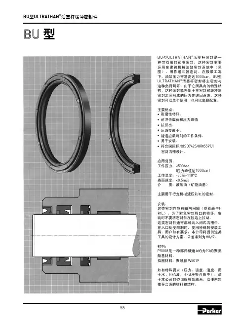
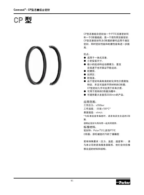
欧陆传动ULTRATHAN ®BU ULTRATHAN® ( ) 1000bar BU ULTRATHAN®• • • •• ••ISO 7425/II 5597/I500 bar ( 1000 bar) -35 + 110 C 0.5 m/s ( )( H L) H8/f7 P5008 A 93ISO 5597/I:W5019HFA HFB )BU 型ULTRATHAN ®活塞杆缓冲密封件BU 型ULTRATHAN ®活塞杆密封是一种带挡圈的紧凑密封。
这种密封主要运用在建筑机械油缸密封系统中(见图),用作缓冲器密封。
在极限工况下,油缸压力常常高达1000bar 。
BU 型ULTRATHAN ®活塞杆密封将主密封与这种负荷隔开。
由于它所具有的特殊结构,这种密封能将处于主密封和缓冲器密封之间形成的压力传递回系统。
这种密封可以单个使用,也可以串联配置。
主要优点:● 耐磨性特好。
● 耐冲击载荷和压力峰值● 抗挤出。
● 压缩变形小。
● 能适应最苛刻的工作条件。
● 易于安装。
● 符合国际标准ISO7425/II 和5597/I密封沟槽设计。
应用范围:工作压力:≤500bar(压力峰值达1000bar)工作温度:-35至+110°C 表面速度:≤0.5m/s 介 质:液压油(矿物油基)主要用于行走机械液压油缸的密封。
安装:这类密封件应有轴向间隙(参看表中H 和L )。
为了避免密封唇口的损坏,安装时不要将密封件在锐边上拉动。
这类密封件通常都可装入闭式沟槽中。
在入口处受限制时,要用特殊的安装工具。
用户如有要求,本公司将提供这类工具的设计方案,公差准则为H8/f7。
材料:P5008是一种邵氏硬度A 约为93的聚氨酯基材料。
挡圈材料:聚酰胺 W5019如有特殊要求(压力、温度、速度、用于水、HFA 液、HFB 液等介质中),请于本公司的咨询服务部联系,以便向您推荐合适的材料和结构。

Sealing SolutionsMiniature Elastomer SealsParker is able to create high qualityand consistent biocompatibleParFab™ Extruded Profi lesParker offers a wide variety ofPTFE FlexiSeals®Our full line of spring energized PTFE lip seals are used on rod, Composite SealsParker’s composite seals are rubber-to-metal, or rubber-to-plastic customFDA and USP Class VI Seal CompoundsO -r i n g s / C u s t o m M o l d e dE x t r u d e d P r o fi l e sMaterialHardness(Shore A)ColorComments ETHYLENE PROPYLENE – materials with temperature range -70°F to 250°F X XE7001-6060Black FDA X E1028-7070Black FDA X X E7736-7070Black FDAXE3609-7070Black FDA, USP Class VI X E7925-7070Black FDAX EJ590-7070White FDA, USP Class VI X E7871-7575Black FDA XE7126-8080Black FDA FLUOROCARBON – materials with temperature range -15° to 400°FX V0680-7070Red FDA X X V7108-7070White FDA X V1274-8080Black FDA PERFLUORINATED – materials with temperature range -5° to 608°FX FF200-7575Black FDAX FF350-7575White FDA, USP Class VI X FF500-7575Black FDA X V8545-7575Black FDA X V8562-7575White FDA NITRILE - materials with temperature range -30° to 225°FX N1219-6060Black FDA X NJ253-7070Black FDA X N1220-7070Black FDA XN1069-7070Black FDA XN7068-7070Black FDA XN0508-7575Black FDA XN7219-8080Black FDA SILICONE - materials with temperature range -60° to 450°FXS0802-4040White FDA X S7577-40(1)40Translucent USP Class VI XS7317-4040Translucent FDA XS7442-4040Rust FDA XXS7561-4040White FDA X S7433-50(1)50White USP Class VI X S7489-50(1)50Translucent USP Class VI X S7318-5050White FDA X S7405-5050Translucent FDA X S7435-5050Rust FDA X S7469-5050Red FDAXS1538-5555Translucent FDA, USP Class VI X S7530-55(1)55Translucent USP Class VI X S7311-5555Rust FDA X S7396-5555White FDAXS0317-6060RustFDA, USP Class VIO -r i n g s / C u s t o m M o l d e dE x t r u d e dP r o fi l e sMaterial Hardness(Shore A)Color Comments SILICONE - materials with temperature range -60° to 450°F (continued) X S7490-60(1)60Translucent USP Class VI X S7349-6060Red FDA X S7350-6060Green FDA X S7351F-6060White FDA X S7354-6060Blue FDA X S7355-6060White FDA X S7359-6060Black FDA X S7413-6060Rust FDA X S7526-6060Yellow FDA X S1138-7070Rust FDA X S7387-70(1)70Translucent USP Class VI X S7492-70(1)70Translucent USP Class VI X S7314F-7070Black FDA X S7494-7070Red FDA X S7525-7070White FDA X S0355-7575Rust FDA X S7386F-7575White FDA X S7383-80(1)80White USP Class VI X S7300F-8080White FDA X S7309-8080Black FDA X S7313-8080Blue FDA X S7548-8080Blue FDA X S7568-8080Red FDA THERMOPLASTIC - materials with temperature range -76° to 275°FX J7976-4545Beige USP Class VI X J7976-5555Beige USP Class VIXJ7737-5555Black USP Class VI X J7969-5555Beige FDA X J7813-5555Black FDA X J7902-6464Beige USP Class VIXJ7974-6464Black USP Class VI X J7959-6464Beige FDA X J7967-6464Black FDA X J7876-7373Beige USP Class VIXJ7975-7373Black USP Class VI X J7267-7373Beige FDA X J7968-7373Black FDA X J7970-8080Beige FDAXJ7907-8787Beige USP Class VI X J7971-8787Beige FDA X J7977-40D 40(2)Beige USP Class VI X J7972-40D40(2)Beige FDA XJ7973-50D50(2)BeigeFDA(1) Platinum cured silicone rubber(2) Hardness of compound is Shore DYour Local Authorized Parker Distributor © 2007 Parker Hannifi n Corporation. Product names are trademarks or registered trademarks of their respective companies.PSG 5028 2.5 AMD 10/07Parker Hannifi n CorporationEngineered Materials Group6035 Parkland BoulevardCleveland, OH 44124phone800 C PARKER/emg。
Piston PumpsCatalog HY28-2662-CD/US Revised June, 2012Quick Reference Data ChartDisplacement Pump Delivery† Approx. Noise Levels dB(A)Input Power AtOperating PressurePumpcc/rev @ 21 bar (300 PSI)@ Full Flow 1800 RPM (1200 RPM)1800 RPM, Max.Speed (RPM)bar (PSI)Model(In3/rev)in LPM (GPM)34 bar69 bar138 bar207 bar248 bar Displacement &(Maximum)Continuous 1200 RPM1800 RPM(500 PSI)(1000 PSI)(2000 PSI)(3000 PSI)(3600 PSI)248 bar (3600 PSI)(Maximum)PVP1616(.98)19.7(5.2)29.5(7.8)53 (47)55 (50)59 (54)62 (56)65 (59)13.1 kw (17.5 hp)3000248 (3600) PVP2323(1.4)28.0(7.4)42.0(11.1)61 (57)64 (59)67 (63)69 (65)70 (65)19.7 kw (26.5 hp)3000248 (3600) PVP3333(2.0)39.4(10.4)59.0(15.6)64 (59)66 (59)68 (62)70 (64)71 (65)27.2 kw (36.5 hp)3000248 (3600) PVP4141(2.5)49.2(13.0)73.8(19.5)68 (60)70 (61)73 (65)74 (67)75 (69)33.2 kw (44.5 hp)2800248 (3600) PVP4848(2.9)57.6(15.2)86.4(22.8)69 (60)71 (62)73 (65)75 (68)76 (69)40.3 kw (54.0 hp)2400248 (3600)†Measured in an anechoic chamber to DIN 45635, measuring error + 2 dB(A).Fluid used: petroleum oil to ISO VG 46; temperature = 50°C (122°F).Since many variables such as mounting, tank style, plant layout, etc., effect noise levels, it cannot be assumed thatthe above readings will be equal to those in the field. The above values are for guidance in selecting the proper pump.Features•High Strength Cast-Iron Housing •Fast Response Times•Two Piece Housing For Ease of Service •Metric Pilot, Shaft and Ports Available •Replaceable Bronze Clad Port Plate •Thru-Shaft Capability •Low Noise Levels•Replaceable Piston Slipper PlateControls•Pressure Compensation •Load Sensing•Horsepower Limiting•Horsepower and Load Sensing •Remote Pressure Compensation •Adjustable Maximum Volume Stop •Hi/Lo Torque (Power) Limiting (PVP 41/48, 60/76, 100/140 Only)•Low Pressure StandbySERVO COMPENSA TORPUMP CASE BIAS PLA TE BARREL PLA TE BEARING SEALGeneral DescriptionAll control is achieved by the proper positioning of the swash plate. This is achieved by a servo piston acting on one end of the swash plate working against the combined effect of the off-setting forces of the pistons and centering spring on the other end. The control spool acts as a metering valve which varies the pressure behind the servo piston.As shown in Figure 1, the amount of flow produced by the Parker Piston Pump is dependent upon the length of stroke of the pumping pistons. This length of stroke, in turn, is determined by the position of the swash plate. Maximum flow is achieved at an angle of 15-17degrees. The rotating barrel, driven by the prime mover, moves the pistons in a circular path and the piston slippers are supported hydrostatically against the face of the swash plate. When the swash plate is in a vertical position, perpendicular to the centerline of the piston barrel, there is no piston stroke and consequently no fluid displacement. When the swash plate is positioned at an angle, the pistons are forced in and out of the barrel and fluid displacement takes place. The greater the angle of the swash plate, the greater the piston stroke.Control OptionsBARRELPressure Compensated Control (OMIT)The swash plate angle controls the output flow of the pump. Swash plate angle is generated by the hydraulic force of the pumping pistons and the mechanical force of the swash plate bias spring. Control of the pump’s outlet flow is obtained by over-riding the force of the pumping pistons and bias spring with the hydraulic force of the servo piston by means of internal porting. Pressure is connected from the outlet port to the servo piston via a compensator spool.The compensator spool is held against the spring guide by the outlet pressure. When the outlet pressure reaches the setting of the compensator control, the compensator spool moves, allowing outlet pressure oil to be metered into the servo piston. This metered oil provides adequate force to power the servo piston and override swash plate forces. The outlet pressure causes the servo piston to move which reduces the angle of the swash plate and thereby reduces the pump’s output flow. When flow is again demanded by the system, the outlet pressure will momentarily fall allowing the compensator spool to move. This movement closes off the outlet pressure to the servo piston and vents the servo piston to case. The result of this venting allows the swash plate forces to move the swash plate angle to maximum displacement, thus responding to the demand for additional flow. Note that the compensator spring chamber is vented to the pump case via a hole internal to the compensator spool.PORTRemote Pressure Control (M)The pump swash plate actuation is identical to the standard pressure compensator but can be controlled via a remote pressure control.Remote control of the pump output pressure can be achieved by controlling the pressure at port A, Figure 3 on the compensator. Flow is metered through the orifice in the spool from outlet pressure into the spring chamber. The spring chamber pressure is limited by an external relief connected to port A. The controlled pressure at port A is sensed at the differential spring chamber. The compensator spool will move to the right when the pump outlet pressure reaches a force equal to the differential spring setting plus the controlled port pressure setting. When the spool moves to the right, outlet pressure oil is metered to the servo piston and the pump swash plate angle is controlled accordingly. With this option the pump outlet pressure can be controlled and varied from a remote location.This control also incorporates a pressure limiting feature preset at the factory. When the pressure in the differential spring chamber reaches the maximum relief setting, the dart unseats allowing the spring chamber to vent to the pump case and limits the maximum pressure attainable.Control OptionsCatalog HY28-2662-CD/USFlow Control (Load Sensing) (A)Figure 4 shows a PVP pump with flow control. The control is identical to the remote pressure compensation control except for an integral orifice, a solid compensator spool and adjustable differential pressure control. Port A is connected downstream of an orifice (variable or fixed) to sense the actual working pressure required. This pressure plus the differential spring force act on the right side of the compensatorspool and will urge the spool to the left until output pressure acting on the left side of the spool balances the forces. As the load increases, output pressure will increase and maintain a constant differential pressure across the orifice and thus a constant flow.Maximum pressure is limited by the internal dart setting.This setting is adjustable up to the maximum preset at the factory.Variable Volume Piston PumpsSeries PVPControl OptionsPORTCatalog HY28-2662-CD/USPressure & Power Control (H)This control option is a T orque Limiting Control, but for constant speed applications it is generally referred to as a Horsepower Control. This control works in conjunction with the Remote Pressure Compensator,control option “M”. A second pressure control device called a horsepower control block, is assembled to the main pump housing. The HP block is plumbed to one of the ports on the remote compensator via steel tubing.The control dart in the HP block and the maximum pressure compensator dart in the remote compensator are connected in parallel. What makes the control dart in the HP block different from any other external relief valve is the pressure setting is mechanically linked to the pump swashplate angle.The cracking pressure of the HP dart is generally lower than the cracking pressure of the remote compensator differential spring cavity is lowered allowing the compensator spool to meter system pressure in the servo piston. As the servo piston extends, it rotates the swashplate and in turn rotates the HP cam. As the cam rotates it increases the force on the HP dart control spring. As the system pressure is allowed to increase,the pump gradually reduces its stroke (flow). When the system pressure reaches the setting of the maximum pressure dart the normal action of the remote compensator takes over. If the HP control is set low enough, the pump may reach zero stroke before the system pressure ever gets a chance to open the maximum compensator dart. This should be considered when making low power settings on systems requiring high working pressures.Variable Volume Piston Pumps Series PVPControl OptionsCatalog HY28-2662-CD/USPressure, Power & Flow Control (C)Refer to the previous section(s) on Flow Control and Power Control. This is another case where multiple controls can be combined in parallel. Since the Power Control is just a special version of Remote Pressure Control, it can be combined with the Flow Control (Load Sense) option. The main point to remember here is that the pressure drop which is required to begin and maintain compensation comes from an external device (such as a proportional valve). This sensed pressure drop will control flow until one of the limits of the other controls has been exceeded. The pump will always respond to the lowest control setting for any given pressure. In addition to Load Sensing, Power Control,and on-pump Pressure Control, Remote Pressure Control can also be included in this parallel device package. There is a remote port on the compensator body and one on the HP Control body, either of which may be used for remote pressure control. The important concept to remember in load sense circuits is that each pressure control device in and connected to the compensator must be protected from saturation. For this reason, use only the uppermost port on the compensator for connection of the load sense line and insure that an appropriate orifice is installed. All control options using a load sense compensator spool are supplied with this orifice.Variable Volume Piston Pumps Series PVPControl OptionsCatalog HY28-2662-CD/USHi/Lo Power Control (HLM)(Available with PVP41 and PVP48 Only)The graph shown below represents the flow-pressure characteristics of a Hi-Lo control for PVP pumps. There are up to four separate adjustments that must be made with the pump controls to get a particular setting, all of which influence the shape of the curve. To get the proper settings, it is very important that all pertinent information is supplied with each Hi-Lo pump ordered.As you can see from the graph below, there are two peak power points. Our intention is to have the same magnitude of power required for both peaks. Of course many combination of settings are possible but specification of the settings becomes very difficult. To make factory settings, we need to know the required flow (applicable if pump has a maximum volume stop), the shaft speed , the required Power limit , and the compensation pressure . Based on these requirements, we will adjust the low pressure set point and the reduced flow set point of the Hi-Lo control to best match the requested parameters called out on the order.Important note: As with power controls, not all combinations of flow, power, pressure, etc. are possible.pressure or in a de-stroked condition can have a much lower overall efficiency than expected. The other thing to keep in mind is that the pump will require the peak power at only two points. All other operating pressures will require less than maximum power and therefore the pump will deliver less hydraulic power in the appropriate ratio based on the actual pump efficiency at those conditions.System PressureO u t l e t F l o wTypical Hi-Lo ControlFlow/Pressure CharacteristicsVariable Volume Piston Pumps Series PVPControl OptionsPVP SERIESPRESSURE & POWER COMPENSATORCONTROL OPTION "HLM"Performance InformationSeries PVP16 Pressure Compensated,Variable Volume, Piston PumpFeatures•High Strength Cast-Iron Housing for Reliability and Quiet Operation•Optional Inlet/Outlet Locations for Ease of Installation•Replaceable Bronze Port Plate •Replaceable Piston Slipper Plate•Thru-Shaft Capability SAE A Pilots Offered •Low Noise Levels - Promote More Comfortable Operating Environment •Fast Response Times•Metric Pilot Shaft and Ports AvailableControls•Pressure Compensation•Remote Pressure Compensation •Load Sensing•Torque (Power) Limiting•Adjustable Maximum Volume Stop •Low Pressure StandbySchematic Symbol(Basic Pump)Quick Reference Data ChartDisplacementPump Delivery † Approx. Noise Levels dB(A)Input Power At Pump cc/rev @ 21 bar (300 PSI)@ Full Flow 1800 RPM (1200 RPM)1800 RPM, Max.Model (In 3/rev)in LPM (GPM)34 bar 69 bar 138 bar 207 bar 248 bar Displacement &1200 RPM 1800 RPM (500 PSI)(1000 PSI)(2000 PSI)(3000 PSI)(3600 PSI)248 bar (3600 PSI)PVP1616.4 (1.0)19.7 (5.2)29.5 (7.8)53 (47)55 (50)59 (54)62 (56)65 (59)13.1 kw (17.5 hp)†Measured in an anechoic chamber to DIN 45635, measuring error + 2 dB(A).Fluid used: petroleum oil to ISO VG 46; temperature = 50°C (122°F).Since many variables such as mounting, tank style, plant layout, etc., effect noise levels, it cannot be assumed that the above readings will be equal to those in the field. The above values are for guidance in selecting the proper pump.SpecificationsPressure Ratings Outlet Port:248 bar (3600 PSI) Continuous (P1)310 bar (4500 PSI) Peak (P3)Inlet Port:1.72 bar (25 PSI) Maximum.17 bar (5 In. Hg.) Vacuum Minimum @ 1800 RPM (See inlet chart for other speeds)Speed Ratings:600 to 3000 RPMOperating Temperature Range:– 40°C to 71°C(– 40°F to 160°F)Housing Material:Cast-Iron Filtration:Maintain SAE Class 4,Mounting:SAE “A” or Metric 2-Bolt Flange MountInstallation Data:See page 42 of this catalog for specific recommendations pertaining to system cleanliness, fluids, start-up, inlet conditions, shaft alignment, drain line restrictions and other important factors relative to the proper installation and use of these pumps.*Available with CW rotation only.NOTE: The efficiencies and data in the graph are nominal values and good only for pumps running at 1800 RPM and stroked to maximum. To calculate approximate horsepower for the other conditions, use the following formula:Actual GPM is directly proportional to drive speed and maximum volume setting. Flow loss, however, is a function of pressure only.HP = Q x (PSI) + (CHp)1714[ ]WHERE:Q =Actual Output Flow in GPM PSI =Pressure At Pump OutletCHp =Input Horsepower @ Full Compensation @ 1800RPM(from graph read at operating pressure)45678910100908070F l o wE f f i c i e n c y - %P o w e rPVP16 @ 1200 RPM021315.118.922.726.530.334.137.907.63.811.400Bar PSI 691000138200020730002754000Pressure LPM 03.06.08.911.914.904.08.012.016.020.0HP KW 4567891010090807060F l o wE f f i c i e n c y - %P o w e rPVP16 @ 1800 RPM021315.118.922.726.530.334.137.907.63.811.400Bar PSI 691000138200020730002754000PressureLPM 03.06.08.911.914.904.08.012.016.020.0HP KW12.015.0O u t l e t F l o w @ M a x . D i s p l a c e m e n tFlow vs. Speed010002000300050015002500Shaft Speed - RPM6.03.09.045.557.8022.711.434.1GPM LPM PVP16Inlet Characteristics at Full Displacement(Graph only valid at sea level)10001500500200025003000Shaft Speed - RPMV a c u u mI n l e t P r e s s u r e 6.414.282.14PSI bar 005.1710.3415.5120.68barPower ControlFull Flo w TorquePSI 1000200030004000PressureF l o wT o r q u e012.424.837.049.561.9011022033044055074.3660In-LbsN·mFull Flo w TorquePSI 1000200030004000PressureF l o wT o r q u e09.018.027.036.045.008016024032040054.048063.056072.0640In-LbsN·m T i m e (m i l l i s e c )PVP16 @ 1200 RPM00Bar PSI 691000138200020730002754000Pressure 100125150200T i m e (m i l l i s e c )PVP16 @ 1800 RPM50257500Bar PSI 691000138200020730002754000PressurePVP16Compensated Power@ 1800 RPM00Bar PSI 691000138200020730002754000Pressure2.02.53.0P o w e r01.0.51.51.51.92.20.75.371.1HPKW PVP16Approximate Case Drain Flow@ 1800 RPM 00Bar PSI 691000138200020730002754000Pressure .4.5.6F l o w0.2.1.31.51.92.30.8.41.1GPMLPM Response TimesRear Ported Pump Dimensions* Inch equivalents for millimeter dimensions are shown in (**).NOTE:Illustration shows Righthand (CW) rotation pump. Lefthand (CCW)pumps will have inlet and outlet ports reversed with compensator on outlet side.STRAIGHT THREAD O-RING PORT (9/16-18 UNF-2B)(INCLUDED IN “5” OPTION ONL Y)ADJ. MAX. VOLUME STOP (1.6 CC/REV/TURN)“OPTION 2”Front ViewPilot DimensionsPilot A C D Option OMIT N/A 32.00173.23(1.26)(6.82)538.1028.44144.53(1.50)(1.12)(6.44)FLAADJ. MAX.VOLUME STOP(1.6 CC/REV/TURN)“OPTION 2”Rear View Front ViewSide Ported – Options 2 & 4 Dimensions* Inch equivalents for millimeter dimensions are shown in (**).NOTE:Illustration shows Righthand (CW) rotation pump. Lefthand (CCW) pumps will have inlet and outlet ports reversed with compensator on outlet side.Port Size Type and LocationOption A Inlet and Outlet Ports Drain Port 148.843/4" SAE 4-Bolt FlangeSAE-6 Straight Thread 2(5.86)3/8-16 Thread(9/16-18UNC)Std PSI Series (Code 61)4152.40SAE-16 Straight Thread SAE-6 Straight Thread(6.00)(1-5/16-12UN-2B)(9/16-18UNC)Dimensional DataPilot DimensionsShaft A B C D Option Omit 82.55/82.50 6.1053.09ø 3/8"B, C ø (3.250/3.248)(.24)(2.09)K80.00/79.957.2455.63ø 10mmø(3.149/3.147)(.285)(2.19)Side Ported – Options 8 & 9 Dimensions* Inch equivalents for millimeter dimensions are shown in (**).NOTE:Illustration shows Righthand (CW) rotation pump.ADJ. MAX.VOLUME STOP (1.6 CC/REV/TURN)“OPTION 2”Side ViewThru-Shaft Pump Dimensions* Inch equivalents for millimeter dimensions are shown in (**).NOTES:1.Righthand (CW) rotation pump shown above.Counterclockwise (CCW) pump will have inlet and outlet ports reversed with the compensator over the outlet port.2.Splined shaft (option “B”) not recommended withThru-Shaft pumps.3.The maximum torque transmitting capacity for rearmounting of pumps is limited by the allowable torque of the input shaft.4.Options 6A4 and 9A4 Design Series 12 have a gasket.All other options incorporate an o-ring seal and have an o-ring groove.Port Size Type and LocationOption A Inlet and Outlet Ports Drain Port 148.843/4" SAE 4-Bolt FlangeSAE-6 Straight Thread2(5.86)3/8-16 Thread(9/16-18UNC)Std PSI Series (Code 61)4152.40SAE-16 Straight Thread SAE-6 Straight Thread(6.00)(1-5/16-12UN-2B)(9/16-18UNC)148.843/4" SAE 4-Bolt FlangeISO 6149-68(5.86)M10 ThreadM16 x 1.50Std PSI Series (Code 61)148.843/4" SAE 4-Bolt Flange9(5.86)M10 Thread3/8" - BSPPStd PSI Series (Code 61)Dimensions – Thru Shaft OptionsVARIATIONH GFE DC 6A453.19 (2.09)82.58/82.60 (3.251/3.252)N/A 3/8–16UNC–2B 9 T ooth 16/32 Pitch207.26 (8.16)9A453.19 (2.09)82.58/82.60 (3.251/3.252)N/AM10 x 1.509 T ooth 16/32 Pitch207.26 (8.16)Remote Compensator Control Pump Dimensions* Inch equivalents for millimeter dimensions are shown in (**).NOTES:1.Righthand (CW) rotation pump shown below. Lefthand (CCW) pumps will have compensator on opposite side.2.When controlling pump compensator pressure with remote relief valve, remote relief valve must be capable of passing 1.89 LPM (.5 GPM).3.Remote compensator option “M”, “ME” & “A” available on pumps with any port location.PUMPSISO 6149-4“9” OPTION1/4"TEDC L Side View Front ViewDimensional DataDimensional DataPower (Torque) Control Pump Dimensions* Inch equivalents for millimeter dimensions are shown in (**).NOTES:1.Righthand (CW) rotation rear ported pump shown. Counterclockwise (CCW)pumps will have inlet and outlet ports reversed with compensator and powerblock on outlet side.2.Power control shown on rear ported pump. Also available on side ported or thru-shaft option pumps.Side View Front ViewPerformance InformationSeries PVP 23/33 Pressure Compensated, Variable Volume, Piston PumpsFeatures•High Strength Cast-Iron Housing for Reliability and Quiet Operation•Optional Inlet/Outlet Locations for Ease of Installation•Replaceable Bronze Port Plate •Replaceable Piston Slipper Plate•Thru-Shaft Capability SAE A andB Pilots Offered•Low Noise Levels•Fast Response Times•Metric Pilot Shaft and Ports AvailableControls•Pressure Compensation •Remote Pressure Compensation •Load Sensing•Torque (Power) Limiting •Adjustable Maximum Volume Stop •Low Pressure StandbySchematic Symbol(Basic Pump)SpecificationsPressure RatingsOutlet Port:248 bar (3600 PSI) Continuous (P1)310 bar (4500 PSI) Peak (P3)Inlet Port: 1.72 bar (25 PSI) Maximum.17 bar (5 In. Hg.) Vacuum Minimum@ 1800 RPM (See inlet chart forother speeds)Speed Ratings:600 to 3000 RPMOperating T emperature Range:–40°C to 71°C(–40°F to 160°F) Housing Material: Cast-IronFiltration:Maintain SAE Class 4,ISO 16/13,ISO 18/15 MaximumMounting:SAE “B” or Metric 2-BoltFlange MountInstallation Data:See page 42 of this catalog for specific recommendations pertaining to system cleanliness, fluids, start-up, inlet conditions, shaft alignment, drain line restrictions and other important factors relative to the proper installation and use ofthese pumps. Quick Reference Data ChartDisplacement Pump Delivery† Approx. Noise Levels dB(A)Input Power AtPumpcc/rev @ 21 bar (300 PSI)@ Full Flow 1800 RPM (1200 RPM)1800 RPM, Max.Model(In3/rev)in LPM (GPM)34 bar69 bar138 bar207 bar248 bar Displacement & 1200 RPM1800 RPM(500 PSI)(1000 PSI)(2000 PSI)(3000 PSI)(3600 PSI)248 bar (3600 PSI)PVP2323.0 (1.4)28.0 (7.4)42.0 (11.1)61 (57)64 (59)67 (63)69 (65)70 (65)19.7 kw (26.5 hp) PVP3333.0 (2.0)39.4 (10.4)59.0 (15.6)64 (59)66 (59)68 (62)70 (64)71 (65)27.2 kw (36.5 hp)†Measured in an anechoic chamber to DIN 45635, measuring error + 2 dB(A).Fluid used: petroleum oil to ISO VG 46; temperature = 50°C (122°F).Since many variables such as mounting, tank style, plant layout, etc., effect noise levels, it cannot be assumed thatthe above readings will be equal to those in the field. The above values are for guidance in selecting the proper pump.81012141618201009080706050F l o wE f f i c i e n c y - %P o w e rPVP23 @ 1800 RPM042630.337.945.453.060.668.275.7015.17.622.700Bar PSI 691000138200020730002754000PressureLPM 03.06.08.911.914.904.08.012.016.020.017.920.923.924.028.032.0HP KW HP = Q x (PSI) + (CHp)[ ]NOTE: The efficiencies and data in the graph are good only for pumps running at 1800 RPM and stroked to maximum. To calculate approximate horsepower for the other conditions,use the following formula:Actual GPM is directly proportional to drive speed and maximum volume setting. Flow loss, however, is a function of pressure only.WHERE:Q =Actual Output Flow in GPM PSI =Pressure At Pump OutletCHp =Input Horsepower @ Full Compensation @ 1800RPM (from graph read at operating pressure)81012141618201009080706050F l o wE f f i c i e n c y - %P o w e rPVP33 @ 1800 RPM042630.337.945.453.060.668.275.7015.17.622.700Bar PSI 691000138200020730002754000PressureLPM 06.011.917.923.929.808.016.024.032.040.0HP KWFlow vs. Speed10002000300050015002500Shaft Speed - RPM16.028.0Ou t l e t F l o w @ M a x . D i s p l a c e m e n t08.04.012.060.6106.0030.315.245.524.020.090.875.7GPM LPM PVP 23/33Inlet Characteristics at Full Displacement(Graph only valid at sea level)10001500500200025003000Shaft Speed - RPMV a c u u mI n l e t P r e s s u r e 6.414.282.14PSI bar 005.1710.3415.5120.68barPVP23 @ 1800 RPM00Bar PSI 691000138200020730002754000Pressure81012F l o wT o r q u e42630.337.945.4015.17.622.7019.739.459.178.898.40175350525700875118.11050GPM LPM In-Lbs N·m Power ControlPVP33 @ 1800 RPM00Bar PSI 691000138200020730002754000Pressure81016F l o wT o r q u e42630.337.960.61453.01245.415.17.622.7019.739.459.178.898.40175350525700875157.51400137.81225118.11050GPM LPM In-Lbs N·mResponse Times80100120T i m e (m i l l i s e c )PVP 23/33 @ 1200 RPM40206000Bar PSI 691000138200020730002754000Pressure 80100120T i m e (m i l l i s e c )PVP 23/33 @ 1800 RPM40206000Bar PSI 691000138200020730002754000PressurePVP 23/33Approximate Case Drain Flow@ 1800 RPM00Bar PSI 691000138200020730002754000.4.5.6F l o w.2.1.31.51.92.3.7.82.73.00.8.41.1.93.4GPMLPM PVP 23/33Compensated Power@ 1800 RPM00Bar PSI 6910001382000207300027540002.02.53.0P o w e r01.0.51.51.51.92.20.75.371.13.54.02.63.0HP KWRear Ported Pump Dimensions* Inch equivalents for millimeter dimensions are shown in (**).NOTES:1.Righthand (CW) rotation pump shown. Lefthand (CCW) pumps have inlet and outlet ports reversed.2.Pump shown with standard pressure compensator (control option “omit”)..)Side Ported – Options 2 & 3 Dimensions* Inch equivalents for millimeter dimensions are shown in (**).NOTES:1.Righthand (CW) rotation pump shown. Lefthand (CCW) pumps have inletand outlet ports reversed.2.Pump shown with standard pressure compensator (control option “omit”).Port LocationOption A Inlet and Outlet Port148.841-1/4" SAE 4-Bolt Flange 2(3.10)7/16-14 Threads StandardPressure Series (Code 61) 3152.40SAE-20 Straight Thread(3.22)(1-5/8-12UN-2B)Side Ported – Options 8 & 9 Dimensions* Inch equivalents for millimeter dimensions are shown in (**).NOTES:1.Righthand (CW) rotation pump shown.2.Pump shown with standard pressure compensator (control option “omit”).Pilot DimensionsShaft A B C D Option Omit 101.60/101.559.4072.90ø 12.70B, C, D (4.000/3.998)(.37)(2.87)(.50)K100.00/99.959.1469.85ø 12mm(3.937/3.935)(.36)(2.75)Top View Side View Rear ViewThru-Shaft Pump Dimensions* Inch equivalents for millimeter dimensions are shown in (**).NOTES:1.Righthand (CW) rotation side ported pump shown.Lefthand (CCW) pump will have inlet and outletports reversed.2.Install coupler on shaft of rear pump to dimensionshown then lock down coupler using set screws.3.Options, 6A2, 6A4, 9A4 and 9A5 Design Series 20have a gasket seal, all other thru-shaft optionsincorporate an o-ring seal and have ano-ring groove.4.Maximum torque transmitting capacity 209 N•m(1850 in-lbs).Thru-Shaft OptionsGFEDCBAno i t a i r aV6A4238.51 (9.39)82.58/82.60 (3.251/3.252)53.19 (2.09)3/8-16UNC-2B9 Tooth 16/32 Pitch31.75 (1.25)N/A 6A5238.51 (9.39)82.58/82.60 (3.251/3.252)53.19 (2.09)3/8-16UNC-2B11 Tooth 16/32 Pitch31.75 (1.25)N/A 6B3252.48 (9.94)101.63/101.65 (4.001/4.002)73.03 (2.88)1/2-13UNC-2B13 Tooth 16/32 Pitch41.15 (1.62)N/A 6B4252.48 (9.94)101.63/101.65 (4.001/4.002)73.03 (2.88)1/2-13UNC-2B15 Tooth 16/32 Pitch45.97 (1.81)N/A 9A4238.51 (9.39)82.58/82.60 (3.251/3.252)53.19 (2.09)M10 x 1.509 Tooth 16/32 Pitch31.75 (1.25)N/A 9A5238.51 (9.39)82.58/82.60 (3.251/3.252)53.19 (2.09)M10 x 1.5011 Tooth 16/32 Pitch31.75 (1.25)N/A 9B3252.48 (9.94)101.63/101.65 (4.001/4.00)73.03 (2.88)M12 x 1.7513 Tooth 16/32 Pitch41.15 (1.62)N/A 9B4252.48 (9.94)101.63/101.65 (4.001/4.00)73.03 (2.88)M12 x 1.7515 Tooth 16/32 Pitch45.97 (1.81)N/A。
One of the leading causes of cylinder failure is seal failure . Parker offers sealing options that cover the widestassortment of applications in the market, ensuring you can get the right seal for your job. The following bulletin will look at Parker cylinders by series and their sealing options to better assist in your specification of sealing requirements.Parker Sealing TechnologyProvides Unmatched Leak Protection on allIndustrial Hydraulic and Pneumatic CylindersHP - Polyurethane Piston SealKP - Filled PTFE Piston Seal RP - Thermoplastic SealWP - Mixed Media SealJewel Gland2H Piston Seal Types:One of Parker’s core cylinder series, the 2H is a 3000 psi NFPA tie rod hydraulic cylinder available in 1.50”-6.00” bore diameters and up to 240” stroke length. The 2H series piston seal kits utilizeParker’s new universal piston seal design, which addresses the performance balance between low pressure sealability, low friction, extrusion resistance and seal life. One piston style is used for all piston seal and wear ring configurations and will suit all application requirements. This reduces the complexity in maintaining cylinders, saving time and cost.Parker offers 4 unique seal types , asshown in the chart below, that when paired with the right seal class will provide the right sealing for your application. Seal class types are located on page 4.Contact Information:Parker Hannifin Corporation Cylinder Division 500 South Wolf Road Des Plaines, IL 60016phone 847-298-2400******************/cylinder2H Rod Sealing System:Parker’s TS2000 threaded Jewel Gland sealing system acts as an automatic check valve that prevents any appreciable amount of oil to leak past the seals.As the rod strokes out, the TS2000’s multi-sealing edges maintain contact with the rod. This provides a cutting action to shear oil from the rod, allowing the rod to pass out of the rod seal practically dry. Any oil that remains on the rod is stopped by the inner lip of the Wiper-seal and held between it and the rod seal. On the return stroke any dirt collected on the rod is wiped off by the outer lip of the Wiper-seal. At the same time, any oil trapped between the Wiper-seal and the rod seal is returned into the cylinder. The TS2000 Jewel Gland is easily removed for service without loosening tie rods and disturbing the pressure envelope.Additional 2H Sealing Options:For environments that contain fine abrasive particulates Parkerrecommends the Parker Crown Wiper™ for Series 2HD. The 3000 psi NFPA tie rod hydraulic 2HD cylinder is the next step up in Parker’s 2H line for applications that require increased durability and is also available in 1.50”-6.00” bore diameters and up to 240” stroke length. The Crown Wiper is a proven superior alternative to piston rod end boots or metallic wipers that can ingest particulate. It has a sharp leading edge to effectively clean the piston rod and a beveled shape to prevent contaminant intrusion by channeling it away from the gland. It also acts as a secondary seal to wipe clean any oil film adhering to the rod on the extend stroke. Standard Crown Wiper material for Seal Class 1 and 2 service is durable polyurethane. Optional FKM material is available for Class 5 service.The Parker Buffer Seal, installed ahead of the primary rod seal, protects the primary seal from the effects of pressure spikes. The result is increased primary rod seal and wiper seal performance life when in severe applications. Both seals provide superior protection against harmful contamination that can damage cylinders causing unnecessary downtime. Buffer Seals are available in class 1, 2, 3, 4, 5 and 6.Buffer SealSealing for RDH:Parker’s heavy-duty hydraulic round-line cylinder series, the RDH is a 3000 psi cylinder available in 1.50”-8.00” bore diameters and up to 240” stroke length. The RDH offers a Tri-Lip Rod Seal and Bi-Directional Piston Seal with proven leak-free performance. Durable polyurethane material is used to maximize seal life. Nitrile end seals and backup rings on a smooth bore of thecylinder body provide optimal sealing and elimination of extrusion problems. Composite rod and piston wear rings are internallylubricated for reduced friction and formulated for heavy-duty, load-bearing applications. Standard rod material is case-hardened, hard chrome plated and polished to an optimum finish. And since we use Parker seals, all seals have immediate availability in other popular compounds.Sealing for 2A/2AN:Parker’s heavy-duty pneumatic cylinder series, the 2A is a 250 psi NFPA tie rod cylinder available in 1”-14” bore diameters and up to 240” stroke length. The 2A provides a serrated lip-seal in its rodgland that has a series of sealing edges which take over successively as pressure increases, providing efficient sealing under all operating conditions. The double lip wiper-seal acts as a secondary seal,cleaning the rod on the return stroke. Its outer lip prevents the ingress of dirt into the cylinder, extending the life of the gland and seals, minimizing costly replacements.Parker Series 2AN, the non-lubricated version of the 2A, and comes with Non-Lubricated Rod Seals. These seals with special rounded sealing lips are supplied as standard for all non-lubricated applicationsand provide all the same benefits as the 2A rod sealSealing for 3L:For use in applications that require lighter duty than the 2H, Parker’s 3L series is a 1000 psi NFPA tie rod hydraulic cylinder available in 1.00”-8.00” bore diameters and up to 240” stroke length. The 3L’s Piston Lip-seals provide zero leakage under static conditions. Seals are self-compensating to conform to variations in pressure, mechanical deflection, and wear, and have back-up washers to prevent extrusion.The 3L Series also utilizes the TS2000 Rod Seal System with its proven leakproof design. It is completely self-compensating and self-relieving to withstand variations and conform to mechanical deflection that may occur. All these features result in a cylinder seal that will withstand the rigors of your applications reducing maintenance costs.CHE/CHD Seal Design:Parker offers two compact hydraulic cylinders, the 140 bar aluminum CHE with up to 150mm stroke length and the 207 bar steel CHD with up to 100mm stroke length, both are available in 20mm to 100mm bore diameters. These compact cylinders include 4 key elements to keep your cylinder leak free:1. Primary Seal – polyurethane rod seal with multiple sealing edges is self-compensating and self-relieving to withstand pressure variations and conform to mechanical deflection that may occur.2. Secondary Seal (Rod Wiper) – wipes clean any oil film adhering to the rod on the extend stroke and cleans the rod on the return stroke.3. Bi-Directional Piston Seal – Polyurethane seal ring with energizer provides leak-free performance.4. Non-Metallic Wear Band – improves resistance to bearing loadsNon-Metallic Wear BandPrimary SealBi-DirectionalPiston SealPiston SealSeal Classes:deterioration from fluid incompatibility or premature wear.expertise in sealing technology. This expertise provides ourcustomers with the knowledge to pick the right seal class andminimize costly replacements.Two main factors in choosing the right seal are fluid type andtemperature. The chart below is a quick guide to which class ofseal to use in your application:*EPR seals are not compatible with hydraulic oil**Fluorocarbon Seals are not suitable for use with Skydrol fluid, but can be used with hydraulic oil if desired.HY08-4100-B1/NA April 2020© 2020 Parker Hannifin Corporation。