太阳能相关英文文献翻译
- 格式:doc
- 大小:59.00 KB
- 文档页数:18

毕业设计(论文)外文文献翻译文献、资料中文题目:太阳能在城市使用的规划文献、资料英文题目:Solar Urban Planning and Design 文献、资料来源:文献、资料发表(出版)日期:院(部):专业:班级:姓名:学号:指导教师:翻译日期: 2017.02.14本科毕业设计外文文献及译文文献、资料题目:Solar Urban Planning and Design 文献、资料来源:期刊外文文献:Solar Urban Planning and DesignAbstract:In recent decades, urban population growth, the acceleration of energy consumption and energy price, the increase of public concerns about environmental pollution and the demolition of nonrenewable energies, have adverted the attention of different groups to the use of sustainable, available and clean solar energy as a sustainable energy.Specialists like architects and engineers have considered solar energy in designing systems, buildings and equipments. Straggle success achieved in the case, cause the progress of replacing solar systems in buildings and equipments instead of systems consuming unsustainable resources like fossil fuel to be accelerated. But they have not applied coherently yet. In other words, before the enforcement of solar projects in cities, it is necessary to note all the dimensions related to their execution in order to reach their optimum efficiency. The goal that could be attained by long-time and multi dimensional planning.This paper guides the focus of urban and town planning and design on the application of solar energy. That urban planners should consider three aspects of environment, economy and society in three related elements of cities consisting buildings and urban spaces, urban infrastructures and urban land uses to achieve sustainable goals is discussed in this paper. So, after the review of few experiences, the issues and guidelines whose consideration lead to the more efficient solar urban planning and design are outlined.Key words:Solar Urban Planning- Solar Potential- Sustainable City- Solar Master Plan- Smart Infrastructure1. Introduction: the increase of attention to solar energyThe increase of urban population, activities and technologies using fossil fuels, energy price, energy consumption and the increase of public concerns about environmental pollution and the destroy of non-renewable energy resources, are causing different experts including specialists related to building and construction to look for alternative ways of energy provision. Building professionals have not considered the aim of good design aesthetically more and try to design the。
淮阴工学院毕业设计(论文)外文资料翻译学院:电子与电气学院专业:电气姓名:曹黎斌学号:1101205212外文出处:2011 International Conference on Electronic Devices,(用外文写)Systems and Applications (ICEDSA) 附件: 1.外文资料翻译译文;2.外文原文。
注:请将该封面与附件装订成册。
附件1:外文资料翻译译文太阳能热水器远程监控系统摘要:本文设计了一种由应用软件和硬件设备构成的能够对太阳能的使用情况进行远程监控的集成系统,该系统已经设计、实现并安装了。
目前,这种系统预期对当前来自管理处和消费者保障处监控的太阳能设备的热水温度、水箱热水量及消耗的热水量进行实时测量。
此外,可以对太阳能利用的辅助子系统发出命令和控制信号。
硬件设备(目前的太阳能热水器)安装在远处,而应用软件安装在公司PC 机或笔记本电脑上。
蜂窝网络被用来从全球任何覆盖蜂窝网络的地方访问远程设备进行数据检索或发出控制指令。
关键词:太阳能,远程监控,控制,热水器一、介绍约旦没有天然气石油资源,完全依靠进口燃料满足能源需求。
唯一可用的自然能源资源是太阳能。
约旦拥有非常晴朗的天气,平均每天地平面太阳辐射量为6.5KWh/m2。
在约旦,配置太阳能装置很贵的。
这些装置大多数是thermosyphonic 类型的。
这种类型的太阳能热水器由两个吸收面积在3至4平方米之间的平板式或真空集热管式太阳能集热器、一个容量为150至180升的储罐和一个冷水储罐。
这些都安装在一个合适的框架内。
一个用于集中供热协助产生热水的辅助电热管或逆流交换器在冬天低太阳辐射的阶段使用。
由于太阳能热水器的生产和安装在约旦快速发展,有必要开发一种远程监控及控制系统和研究大型商业机构远程维修的适用性。
普适计算是一种信息化空间和物理空间的无缝结合。
人们能在任何时间任何地点得到数字服务。
如GPRS, EDGE,3G,和WiMAX等相对较新的互联网和无线接入技术提供比基本的第二代GSM系统更高的数据(率)传输速度,提供未来远程监测及高端设计的控制方案。

太阳能英语作文英文回答:Solar energy is a renewable energy source that is derived from the sun's radiation. It is a clean, sustainable, and cost-effective alternative to fossil fuels. Solar energy can be used to generate electricity, heat water, and power homes and businesses.Solar energy is harnessed using photovoltaic (PV) panels, which are made up of semiconductor cells that convert sunlight into electricity. These panels can be installed on rooftops, in fields, or on other surfaces that receive sunlight. The electricity generated by solar panels can be used to power homes and businesses, or it can besold back to the grid.Solar energy is a rapidly growing industry. In 2020,the global solar PV market was valued at $132.4 billion,and it is expected to grow to $262.1 billion by 2025. Thisgrowth is being driven by a number of factors, including the falling cost of solar panels, the increasing demand for clean energy, and the growing awareness of the environmental benefits of solar energy.Solar energy has a number of benefits over other forms of energy. It is a renewable resource, which means that it will never run out. It is also a clean source of energy, as it does not produce any emissions that contribute to climate change. Additionally, solar energy is a cost-effective source of energy, as the cost of solar panels has fallen significantly in recent years.However, solar energy also has some limitations. It is an intermittent source of energy, which means that it is not always available when it is needed. Solar panels can only generate electricity when the sun is shining, so they are not a reliable source of energy for areas that experience frequent cloud cover. Additionally, solar panels require a lot of space, which can be a challenge in densely populated areas.Despite these limitations, solar energy is a promising source of renewable energy. It is a clean, sustainable, and cost-effective alternative to fossil fuels. As the cost of solar panels continues to fall and the demand for clean energy increases, solar energy is likely to play an increasingly important role in the world's energy mix.中文回答:太阳能是一种可再生能源,它源自太阳辐射。

太阳能发电外文翻译文献(文档含中英文对照即英文原文和中文翻译)Design of a Lead-Acid Battery Charging and Protecting IC in Photovoltaic SystemZENG De-you,LING Chao-dong,LI Guo-gang1.IntroductionSolar energy as an inexhaustible, inexhaustible source of energy more and more attention. Solar power has become popular in many countries and regions, solar lighting has also been put into use in many cities in China. As a key part of the solar lighting, battery charging and protection is particularly important. Sealed maintenance-free lead-acid battery has a sealed, leak-free, pollution-free, maintenance-free, low-cost, reliable power supply during the entire life of the battery voltage is stable and no maintenance, the need for uninterrupted for the various typesof has wide application in power electronic equipment, and portable instrumentation. Appropriate float voltage, in normal use (to prevent over-discharge, overcharge, over-current), maintenance-free lead-acid battery float life of up to 12 ~ 16 years float voltage deviation of 5% shorten the life of 1/2. Thus, the charge has a major impact on this type of battery life. Photovoltaic, battery does not need regular maintenance, the correct charge and reasonable protection, can effectively extend battery life. Charging and protection IC is the separation of the occupied area and the peripheral circuit complexity. Currently, the market has not yet real, charged with the protection function is integrated on a single chip. For this problem, design a set of battery charging and protection functions in one IC is very necessary.2.System design and considerationsThe system mainly includes two parts: the battery charger module and the protection module. Of great significance for the battery as standby power use of the occasion, It can ensure that the external power supply to the battery-powered, but also in the battery overcharge, over-current and an external power supply is disconnected the battery is to put the state to provide protection, the charge and protection rolled into one to make the circuit to simplify and reduce valuable product waste of resources. Figure 1 is a specific application of this Ic in the photovoltaic power generation system, but also the source of this design.Figure1 Photovoltaic circuit system block diagramMaintenance-free lead-acid battery life is usually the cycle life and float life factors affecting the life of the battery charge rate, discharge rate, and float voltage. Some manufacturers said that if the overcharge protection circuit, the charging rate can be achieved even more than 2C (C is the rated capacity of the battery), battery manufacturers recommend charging rate of C/20 ~ C/3. Battery voltage and temperature, the temperature is increased by 1 °C, single cell battery voltage drops 4 mV , negative temperature coefficient of -4 mV / ° C means that the battery float voltage. Ordinary charger for the best working condition at 25 °C; charge less than the ambient temperature of 0 °C; at 45 °C may shorten the battery life due to severe overcharge. To make the battery to extend the working life, have a certain solar battery array Charge controllercontroller Dischargecontroller DC load accumulatorunderstanding and analysis of the working status of the battery, in order to achieve the purpose of protection of the battery. Battery, there are four states: normal state, over-current state over the state of charge, over discharge state. However, due to the impact of the different discharge current over-capacity and lifetime of the battery is not the same, so the battery over discharge current detection should be treated separately. When the battery is charging the state a long time, would severely reduce the capacity of the battery and shorten battery life. When the battery is the time of discharge status exceeds the allotted time, the battery, the battery voltage is too low may not be able to recharge, making the battery life is lower. Based on the above, the charge on the life of maintenance-free lead-acid batteries have a significant impact, while the battery is always in good working condition, battery protection circuit must be able to detect the normal working condition of the battery and make the action the battery can never normal working state back to normal operation, in order to achieve the protection of the battery.3.Units modular design3.1The charging moduleChip, charging module block diagram shown in Figure 2. The circuitry includes current limiting, current sensing comparator, reference voltage source, under-voltage detection circuit, voltage sampling circuit and logic control circuit.Figure2 Charging module block diagramdriverV oltage amplifierV oltage sampling comparatorStart amplifierState level control Charging indicator Logicalmodule Undervoltage detection circuitR- powerCurrent sampling comparator Limitingamplifier Power indicatorThe module contains a stand-alone limiting amplifier and voltage control circuit, it can control off-chip drive, 20 ~30 mA, provided by the drive output current can directly drive an external series of adjustment tube, so as to adjust the charger output voltage and current . V oltage and current detection comparator detects the battery charge status, and control the state of the input signal of the logic circuit. When the battery voltage or current is too low, the charge to start the comparator control the charging. Appliances into the trickle charge state when the cut-off of the drive, the comparator can output about 20 mA into the trickle charge current. Thus, when the battery short-circuit or reverse, the charger can only charge a small current, to avoid damage to the battery charging current is too large. This module constitutes a charging circuit charging process is divided into two charging status: high-current constant-current charge state, high-voltage charge status and low-voltage constant voltage floating state. The charging process from the constant current charging status, the constant charging current of the charger output in this state. And the charger continuously monitors the voltage across the battery pack, the battery power has been restored to 70% to 90% of the released capacity when the battery voltage reaches the switching voltage to charge conversion voltage Vsam charger moves to the state of charge. In this state, the charger output voltage is increased to overcharge pressure V oc is due to the charger output voltage remains constant, so the charging current is a continuous decline. Current down to charge and suspend the current Ioct, the battery capacity has reached 100% of rated capacity, the charger output voltage drops to a lower float voltage VF.3.2 Protection ModuleChip block diagram of the internal protection circuit shown in Figure 3. The circuit includes control logic circuit, sampling circuit, overcharge detection circuit, over-discharge detection comparator, overcurrent detection comparator, load short-circuit detection circuit, level-shifting circuit and reference circuit (BGR).Figure3 Block diagram of battery protectionThis module constitutes a protection circuit shown in Figure 4. Under the chip supply voltage within the normal scope of work, and the VM pin voltage at the overcurrent detection voltage, the battery is in normal operation, the charge and discharge control of the chip high power end of the CO and DO are level, when the chip is in normal working mode. Larger when the battery discharge current will cause voltage rise of the VM pin at the VM pin voltage at above the current detection voltage Viov, then the battery is the current status, if this state to maintain the tiov overcurrent delay time, the chip ban on battery discharge, then the charge to control the end of CO is high, the discharge control side DO is low, the chip is in the current mode, general in order to play on the battery safer and more reasonable protection, the chip will battery over-discharge current to take over the discharge current delay time protection. The general rule is that the over-discharge current is larger, over the shorter the discharge current delay time. Above Overcharge detection voltage, the chip supply voltage (Vdd> Vcu), the battery is in overcharge state, this state is to maintain the corresponding overcharge delay time tcu chip will be prohibited from charging the battery, then discharge control end DO is high, and charging control terminal CO is low, the chip is in charging mode. When the supply voltage of the chip under the overdischarge detection voltage (Vdd <Vdl,), then the battery is discharged state, this state remains the overdischarge delay time tdl chip will be prohibited to discharge the battery at this time The charge control side CO is high, while the discharge control terminal DO is low, the chip is in discharge mode. Sampling circuitOver discharge detection comparatorControl logic circuit Level conversion circuit Overcharge detection comparator Over-current detection comparator2 Over-current detection comparator1Over-current detection circuitLoad short detection circuitFigure4 Protection circuit application schematic diagram4.Circuit DesignTwo charge protection module structure diagram, the circuit can be divided into four parts: the power detection circuit (under-voltage detection circuit), part of the bias circuit (sampling circuit, the reference circuit and bias circuit), the comparator (including the overcharge detection /overdischarge detection comparator, over-current detection and load short-circuit detection circuit) and the logic control part.This paper describes the under-voltage detection circuit (Figure 5), and gives the bandgap reference circuit (Figure 6).Figure5 Under-voltage detection circuitProtectionmoduleBiasing circuit Reference circuit Bleeder circuit difference amplifier Output circuitAmplifierAmplifierFigure6 A reference power supply circuit diagramBattery charging, voltage stability is particularly important, undervoltage, overvoltage protection is essential, therefore integrated overvoltage, undervoltage protection circuit inside the chip, to improve power supply reliability and security. And protection circuit design should be simple, practical, here designed a CMOS process, the undervoltage protection circuit, this simple circuit structure, process and easy to implement and can be used as high-voltage power integrated circuits and other power protection circuit.Undervoltage protection circuit schematic shown in Figure 5, a total of five components: the bias circuit, reference voltage, the voltage divider circuit, differential amplifier, the output circuit. The circuit supply voltage is 10V; the M0, M1, M2, R0 is the offset portion of the circuit to provide bias to the post-stage circuit, the resistance, Ro, determine the circuit's operating point, the M0, M1, M2 form a current mirror; R1 M14 is the feedback loop of the undervoltage signal; the rest of the M3, M4 and M5, M6, M7, M8, M9, M10, M11, M12, M13, M14, composed of four amplification comparator; M15, DO, a reference voltage, the comparator input with the inverting input is fixed (V+), partial pressure of the resistance R1, R2, R3, the input to the inverting input of the comparator, when the normal working of the power supply voltage, the inverting terminal of the voltage detection is lost to the inverting terminal voltage of the comparator is greater than V+. Comparator output is low, M14 cutoff, feedback circuit does not work; undervoltage occurs, the voltage divider of R1, R2, R3, reaction is more sensitive, lost to the inverting input voltage is less than V when the resistor divider, the comparator the output voltage is high, this signal will be M14 open, the voltage across R into M at both ends of the saturation voltage close to 0V, thereby further driving down the R1> R2, the partial pressure of the output voltage, the formation of the undervoltage positive feedback. Output, undervoltage lockout, and plays a protective role.5. Simulation results and analysisThe design of the circuit in CSMC 0.6 μm in digital CMOS process simulation and analysis of the circuit. In the overall simulation of the circuit, the main observation is that the protection module on the battery charge and discharge process by monitoring Vdd potential and Vm potential leaving chip CO side and DO-side changes accordingly. The simulation waveform diagram shown in Figure 7, the overall protection module with the battery voltage changes from the usual mode conversion into overcharge mode, and then return to normal working mode, and then into the discharge mode, and finally back to normal working mode. As the design in the early stages of the various parameters to be optimized, but to provide a preliminary simulation results.Figure7 Overvoltage and under-voltage protection circuit simulation waveform6.ConclusionDesigned a set of battery charging and protection functions in one IC. This design not only can reduce the product, they can reduce the peripheral circuit components. The circuit uses the low-power design. This project is underway to design optimization stage, a complete simulation can not meet the requirements, but also need to optimize the design of each module circuit.光伏系统中蓄电池的充电保护IC电路设计曾德友,凌朝东,李国刚1.引言太阳能作为一种取之不尽、用之不竭的能源越来越受到重视。

太阳能的应用和发展英语作文English Response:Solar Energy: Application and Development.Solar energy, in its essence, is a boundless source of power derived from the sun. Its applications and development have gained significant traction in recentyears due to increasing concerns about climate change and the finite nature of fossil fuels. Let's delve into the various aspects of solar energy utilization and its promising future.Applications:One of the most common applications of solar energy isin generating electricity through photovoltaic (PV) systems. These systems consist of solar panels that convert sunlight directly into electricity. They can be installed onrooftops of residential buildings, commercialestablishments, and even in large solar farms. For instance, my friend Sarah recently had solar panels installed on her roof. Now, she not only saves money on her electricitybills but also contributes to reducing carbon emissions.Solar energy is also widely used for heating purposes, especially in solar water heaters. These systems usesunlight to heat water for domestic, commercial, orindustrial use. I remember visiting a resort last summer where they had solar water heaters installed in their swimming pools. It was fascinating to learn how theyutilized solar energy to maintain the perfect temperaturefor their guests' comfort.Furthermore, solar energy plays a crucial role in providing lighting solutions in remote or off-grid areas through solar-powered LED lights. For example, in rural villages where access to electricity is limited, solarstreet lights have been installed to illuminate pathwaysand enhance safety during the night. My cousin volunteersfor a non-profit organization that installs such lights in underserved communities, making a tangible difference inpeople's lives.Development:The development of solar energy technology has been remarkable, with ongoing advancements aimed at improving efficiency and reducing costs. Innovations like thin-film solar cells, concentrated solar power (CSP) systems, and solar tracking mechanisms have enhanced the effectiveness of harnessing solar energy. Additionally, research in materials science and nanotechnology holds promise for further enhancing solar cell performance.Moreover, policy support and incentives have played a pivotal role in driving the growth of solar energy. Many governments offer tax credits, rebates, and feed-in tariffs to encourage the adoption of solar power systems. In my country, the government recently announced a subsidy program for homeowners who install solar panels, making it more affordable for ordinary citizens to embrace clean energy solutions.Future Prospects:Looking ahead, the future of solar energy appears exceedingly bright. As technology continues to advance and economies of scale are realized, solar power is expected to become even more competitive with conventional energy sources. With increasing public awareness and commitment to sustainability, the demand for solar energy is likely to soar.Furthermore, integration with energy storage systems such as batteries is poised to revolutionize the solar energy landscape. This would enable greater gridflexibility and reliability, allowing solar power to meet demand even when the sun isn't shining. Imagine a future where households rely predominantly on solar energy for their electricity needs, with excess power stored for use during cloudy days or at night.In conclusion, solar energy's applications are diverse and its development is rapidly evolving. Through technological innovation, supportive policies, and growingpublic acceptance, solar power is positioned to play a pivotal role in shaping a cleaner and more sustainable energy future.中文回答:太阳能,应用与发展。
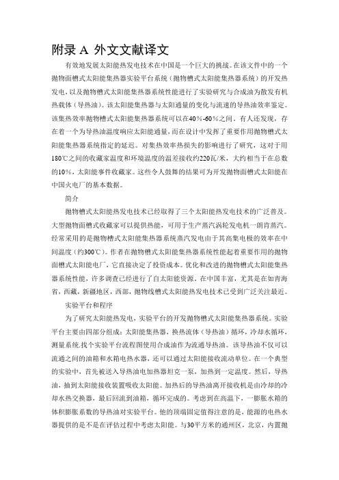
附录A 外文文献译文有效地发展太阳能热发电技术在中国是一个巨大的挑战。
在该文件中的一个抛物面槽式太阳能集热器实验平台系统(抛物槽式太阳能集热器系统)的开发热发电,以及抛物槽式太阳能集热器系统性能进行了实验研究与合成油为散发有机热载体(导热油)。
该太阳能集热器与太阳通量的变化与流速的导热油效率鉴定。
该集热效率抛物槽式太阳能集热器系统可以在40%-60%之间。
有人还发现,存在着一个为导热油温度响应太阳能通量,而在设计中发挥了重要作用抛物槽式太阳能集热器系统指定的延迟。
对集热效率热损失的影响进行了研究,这对于用180℃之间的收藏家温度和环境温度的温差接收约220瓦/米,大约相当于在总数的10%,太阳能事件收藏家。
这些令人鼓舞的结果可为开发抛物面槽式太阳能在中国火电厂的基本数据。
简介抛物槽式太阳能热发电技术已经取得了三个太阳能热发电技术的广泛普及。
大型抛物面槽式收藏家可以提供热能,可用于生产蒸汽涡轮发电机一朗肯蒸汽。
经常采用的是抛物槽式太阳能集热器系统蒸汽发电由于其高集电极的效率在中间温度(约300℃)。
作者在抛物槽式太阳能集热器系统性能起着重要作用的抛物面槽式太阳能电厂,它直接决定了投资成本。
优化和改进的抛物槽式太阳能集热器系统性能,许多调查已经进行了自太阳能资源。
在中国丰富,尤其是在如青海省,西藏,新疆地区,西部,抛物线槽式太阳能热发电技术已受到广泛关注最近。
实验平台和程序为了研究太阳能热发电,实验平台的开发抛物槽式太阳能集热器系统。
实验平台主要由四部分组成:太阳能集热器,换热流体(导热油)循环,冷却水循环,测量系统.找个实验平台流程图使用合成油作为流通导热油。
该导热油不仅可以流通之间的油箱和水箱电热水器,还可以通过太阳能接收流动单位。
在一个典型的实验中,首先被送入导热油电加热器坦克一泵,加热到一定温度。
然后,导热油,抽到太阳能接收装置吸收太阳能。
加热后的导热油离开接收机是由冷却的冷却水热交换器,最后回流到油箱,循环完成的。
太阳能英语作文翻译初一Solar energy is a fascinating and increasingly importanttopic for students to understand, especially in today's world where environmental conservation and sustainable energy sources are of paramount concern. As a junior high school student, learning about solar energy not only expands your knowledge but also equips you with the understanding of a technology that could shape our future.IntroductionSolar energy is the radiant light and heat from the sun that is harnessed using various technologies such as solar panels. It's a clean, renewable source of energy that has the potential to reduce our reliance on fossil fuels and decrease greenhouse gas emissions.The Basics of Solar EnergySolar energy works by converting sunlight into electricity through the photovoltaic effect, which was first discoveredin the 19th century. When sunlight hits a solar panel, it knocks electrons free from atoms, allowing them to flow through the material to create an electric current.Benefits of Solar Energy1. Renewable: Unlike fossil fuels, which are finite, the sunis a continuous source of energy that won't run out for another 5 billion years.2. Clean: Solar energy produces no harmful emissions or pollutants, making it a clean alternative to traditional energy sources.3. Reduces Electricity Bills: By generating your own electricity, you can significantly reduce your monthly energy bills.4. Low Maintenance: Solar panels are durable and requirelittle maintenance over their 25-30 year lifespan.How Solar Energy is UsedSolar energy can be used in various ways:- Homes: Residential solar panels can power homes and appliances.- Businesses: Commercial solar installations can provide energy for businesses and reduce operational costs.- Farming: Solar-powered irrigation systems can help farmers in areas with unreliable electricity.- Space: Solar panels are even used by satellites and space probes to power their systems.Challenges of Solar EnergyDespite its benefits, solar energy faces challenges such as: - Intermittency: The sun doesn't shine at night or on cloudy days, which can limit the availability of solar power.- Cost: Although prices have dropped, the initial cost of solar panels and installation can still be high for some.- Space Requirements: Large arrays of solar panels are neededto generate significant amounts of power, which requires substantial space.The Future of Solar EnergyAs technology advances, the efficiency and affordability of solar panels are expected to improve. Innovations such as solar-powered cars, buildings with integrated solar cells, and better energy storage solutions are on the horizon.ConclusionUnderstanding solar energy is crucial for junior high school students as it is not only a topic in science but also a part of our everyday lives. Embracing solar energy is a step towards a sustainable future where we can meet our energy needs without compromising the environment for future generations.Vocabulary- Photovoltaic effect: The phenomenon that allows sunlight to be converted into electricity.- Renewable energy: Energy that comes from resources thatwill not run out, like the sun.- Fossil fuels: Fuels formed by the decomposition of ancient plants and animals, such as coal, oil, and natural gas.- Greenhouse gas emissions: Gases that trap heat in theEarth's atmosphere, contributing to global warming.- Intermittent: Not continuous or regular in occurrence.By studying this essay, you not only learn about solar energy in English but also gain insights into the potential and challenges of this exciting technology.。
英文翻译Polycrystalline silicon solar cellsAs we all know, solar energy has many advantages, photovoltaic power generation will provide the main energy of mankind, but at present it, to make solar power a large market, is the general consumer acceptance, increased solar cell efficiency and reduce production costs should be our overriding goal, from the current development of the international solar cell can see the trend of its silicon, polycrystalline silicon, ribbon silicon, thin film materials (including trend of its silicon, polycrystalline silicon, ribbon silicon, thin film materials (including microcrystalline silicon thin films, compound-based thin film and dye film).From industrial development, it has been the focus of the direction of single crystal to polycrystalline, mainly due to;(1)the beginning and end of solar cell materials can supply less and less;(2)in terms of the solar cell, a square substrate is more cost-effective, by direct coagulation casting method and obtained direct access to a square polysilicon materials;(3)of polysilicon production technology continue to make progress, casting furnace automatic production cycle of each (50 hours) can produce over 200 kg ingots, grain size to achieve centimeter level;(4)in recent years as research and development of silicon technology quickly, in which technology has been applied to the production of polycrystalline silicon cells, such as selective etching the emitter, back surface field, corrosion suede , surface and bulk passivation, thin metal gate electrode, using screen-printing technology enables the gate electrode width down to 50 microns to 15 microns high, rapid thermal annealing technology for polysilicon production process can significantly shorten the time, single time of thermal process can be completed within a minute using this technology in the 100 square centimeters of silicon chip to make the cell conversion efficiency of over 14%. It was reported in 50 to 60 micron silicon substrate produced more than 16% cell efficiency.Mechanical groove, screen printing technology in polycrystalline on the efficiency of more than 17%, no mechanical groove in the same area on the efficiency of 16%, with buried gate structure, mechanical groove 130 on a square centimeter of polycrystalline cell efficiency of 15.8%.The following two aspects of the polysilicon to discuss battery technology.Laboratory efficient battery technology Laboratory techniques often do not consider the cost of battery production and mass production can only achieve maximum efficiency of the method and means to provide specific materials and processes that can achieve the limit.1.On the absorption of lightFor the optical absorption is mainly:(1)reduce the surface reflection;(2)Change the path of light in the cell body;(3)using the back reflection.For silicon, anisotropic chemical etching method applied in (100) surfaceproduced textured pyramid-shaped, lower surface light reflection. But silicon crystal to deviate from the (100) surface, using the above methods can not make even the suede, the current use of the following methods:(1)laser grooveGroove with a laser method can be produced in the polysilicon surface, inverted pyramid structure, in 500~900nm wavelength range, reflectance was 4 to 6%, with double-layer antireflection coating surface produced considerable. In the (100) reflection of silicon chemical production rate of 11% of the flock. Produced by laser textured surface than in the smooth double-layer antireflection coating film (ZnS/MgF2) short circuit current to increase by about 4%, mainly long-wave light (wavelength greater than 800nm) the reasons for slanting into the battery. Laser production of suede problems in etching, surface damage caused by the introduction of a number of impurities at the same time, through chemical treatment to remove surface damage layer. Solar cells made by this method are usually higher short circuit current, open circuit voltage is not high, mainly due to cell surface area increased, the recombination current increase.(2)Chemical grooveApplication of mask (Si3N4or SiO2) isotropic corrosion, etching solutions for acid etching solutions, but also for the higher concentration of sodium hydroxide or potassium hydroxide solution, the method can not create the kind formed by anisotropic etching cone-like structure. According to reports, the approach down the face of the formation of micron spectral range 700 to 1030 significantly reduced reflex. But the mask layer will be formed at higher temperatures, causing decreased performance polysilicon materials, especially for lower quality polycrystalline materials, reduce the minority carrier lifetime. Application of the technology made of polysilicon in cell conversion efficiency of 16.4%. Mask layer screen printing method can also be formed.(3)reactive ion corrosion (RIE)This method is a non-mask etching process, the formation of suede particularly low reflectivity in the spectral range 450 to 1000 micron reflectivity can be less than 2%. Only from the optical point of view, is an ideal method, but problem is serious silicon surface damage, the battery open circuit voltage and fill factor decreased.(4)produced antireflection filmFor efficient solar cells, the most common and most effective way is to double-layer antireflection coatings deposited ZnS/MgF2, its optimal thickness depends on the thickness of the oxide layer below the surface characteristics and battery, for example, the surface is smooth or textured surface,anti-reflection technology has evaporated Ta2O5, PECVD deposition Si3N3 so. ZnO conductive film can be used as anti-reflective material.2.MetallizationIn the efficient production of the battery, the metal electrode to the battery design parameters such as surface doping concentration, PN junction depth, the metal material to match. General area of small laboratory cell (area less than 4cm2), so they need small metal gate line (less than 10 microns), the general approach to lithography,electron beam evaporation, rge-scale production of industrial plating process is also used, but the combination of evaporation and lithography, do not belong to low-cost technology.3.PN junction formation technology(1)emitter formation and phosphorus getteringFor efficient solar cells, emitter diffusion formation of choice commonly used in the formation of heavy metal impurities in the region below the electrode in the spread between the electrodes to achieve light levels, the shallow emitter diffusion is increased concentration of cell response to blue light, and also allows silicon surface easily passivated. Two-step diffusion method diffusion process, diffusion process and increase corrosion buried diffusion process. Currently used selection proliferation, 15 × 15 cell conversion efficiency of 16.4%, n + +, n + sheet resistance of the surface region were 20Ω and 80Ω.For Mc-Si materials, expansion of phosphorus gettering effect on the battery has been widely studied, a longer period of phosphorus gettering process (usually 3 to 4 hours), make some of Mc-Si of the minority carrier diffusion length increase of two orders of magnitude.(2)the formation of back surface field and aluminum getteringIn Mc-Si cell, the back p + p junction by the formation of uniform diffusion of aluminum or boron, boron source is generally BN, BBr, APCVD SiO2: B2O8 such as evaporation or diffusion of aluminum screen printing of aluminum, 800 degrees completed sintering , on the role of aluminum gettering carried out extensive research, and in different phosphorus diffusion gettering, aluminum gettering at a relatively low temperature. Physical defects which also involved the dissolution and deposition of impurities, while in higher temperatures, the deposition of impurities easily dissolve into the silicon, on the Mc-Si have a negative impact. Far, to the regional background field has been applied to silicon solar cell technology, but in the polysilicon, the application of aluminum or the back surface field structure.(3)Double Mc-Si cellsMc-Si double the battery positive side for the conventional structure, on the back for the N + and P + cross-cutting structure, so that generated a positive light, but in the back of the photo birth rate near the back electrode can be effectively absorbed. Back electrode as an effective complement to the positive electrode, also planted as an independent flow of sub-collector on the back of the light and the scattered light to be effective, it was reported in the AM1.5 conditions, the conversion efficiency of over 19%.360毕业设计网4.Surface and bulk passivationFor Mc-Si, due to higher grain boundary exist, point defects (vacancies, interstitial atoms, metal impurities, oxygen and nitrogen and their compounds) and in vivo defect on the surface passivation is particularly important, in addition to the previously mentioned The gettering, the passivation process has a number of ways, by thermal oxidation to silicon dangling bonds saturated is a relatively common method, make Si-SiO2interface recombination velocity greatly decreased, the passivation effect depends on the launching area surfaceconcentration, the interface state density and the electron and hole cross sections were floating. Annealed in hydrogen atmosphere can passivation effect is more obvious. Nitride deposited by PECVD the recent positive is very effective because the process of film has the effect of hydrogenation. The process can also be applied to large scale production. Application of Remote PECVD Si3N4 surface recombination velocity is less than can 20cm / s.多晶硅太阳能电池众所周知,利用太阳能有许多优点,光伏发电将为人类提供主要的能源,但目前来讲,要使太阳能发电具有较大的市场,被广大的消费者接受,提高太阳电池的光电转换效率,降低生产成本应该是我们追求的最大目标,从目前国际太阳电池的发展过程可以看出其发展趋势为单晶硅、多晶硅、带状硅、薄膜材料(包括微晶硅基薄膜、化合物基薄膜及染料薄膜)。
文献翻译英文原文:Solar electrical energy generationAlong with economical development, society's progress, the people to the energy proposed that more and more high request, seeks for the new energy to become the urgent topic which the current humanity faces. The existing energy mainly has 3 kinds, namely thermal power, water and electricity and nuclear power.The thermal power needs to burn fossil fuels and so on bunker coal, petroleum. On the one hand the fossil fuel reserves limited, the fever are less, is facing the danger which dries up. It is estimated that the world oil resource will have 30 years then to dry up again. On the other hand the combustion fuel will discharge CO2 and the sulfur oxide compound, will therefore cause the greenhouse effect and the acid rain, will worsen the terrestrial environment.The water and electricity must submerge the massive lands, has the possibility to cause the ecological environment to destroy, moreover large reservoir, once collapses, the consequence will be inconceivable. Moreover, country's hydro-electric resources are also limited, moreover must receive the season influence.The nuclear power in the normal condition no doubt is clean, but has the nuclear leakage accidentally, the consequence is similarly fearful. The former Soviet Union Chernobyl Nuclear Power Station accident, has caused 9,000,000 people to receive the varying degree harm, moreover this influence has not terminated.These force the people to seek for the new energy. The new energy must simultaneously meet two conditions: First, the implication rich will not dry up; Second, is safe, is clean, will not threaten the humanity and the destruction environment. At present found the new energy mainly had two kinds:first, solar energy; second, fuel cell. Moreover, the wind power generation may also be the auxiliary new energy. And, the most ideal new energy is greatly positive energy.1. The solar electrical energy generation is the most ideal new energyShines is huge on Earth's solar energy, about 40 minutes shine on Earth's solar energy, then sufficiently supplies global humanity one year energy the expense. It can be said that the solar energy is true inexhaustible, the inexhaustible energy. Moreover the solar electrical energy generation is absolutely clean, does not have the environmental damage. Therefore the solar electrical energy generation is honored asis the ideal energy.Obtains the electric power from the solar energy, must carry on the electro-optical transformation through the greatly positive battery to realize. It completely was formerly different with other power source electricity generation principle, has the following characteristic: ①Non-depletion danger; ②Clean (does not have environmental damage) absolutely; ③It is not distributed the resources the region the limit; ④But is using electricity place nearby generates electricity; ⑤The energy quality is high; ⑥The user easy to accept from the sentiment; ⑦The gain energy expenditure's time is short. The deficiency is:①The illumination energy distribution density is small, namely must take the huge area; ②Obtains the energy with four seasons, the day and nights and cloudy clear and so on meteorological conditions concerns. But generally speaking, the flaw does not cover the fine jade, takes the new energy, the solar energy has the enormous merit, therefore receives various countries the value.Must enable the solar electrical energy generation to achieve the practical level truly; first, must raise the solar energy electro-optic conversion efficiency and reduce its cost; second, must realize the solar electrical energy generation with present's electrical network networking.At present, solar panels mainly has the mono-crystalline silicon, the polycrystalline silicon, the amorphous state silicon three kinds. The mono-crystalline silicon solar cell conversion efficiency is highest, has reached above 20%, but the price is also the most expensive. The amorphous state silicon solar cell conversion efficiency is lowest, but the price is the cheapest, from now on most will be hopeful uses in generally generating electricity will be this kind of battery. Once its big area module electro-optic conversion efficiency achieves 10%, each watt generating set price falls to 1-2 US dollars, then sufficiently compete with present's electricity generation way. It is estimated that at the end of this century it may achieve this level.Certainly, in the special use and the laboratory uses the solar cell efficiency must be much higher, if the US Boeing develops by the gallium arsenic semiconductor with the positive electricity place which too the stibium gallium semiconductor overlaps becomes, the electro-optic conversion efficiency may reach 36%, has caught up with the coal-burning electricity generation efficiency quickly. But because it is too expensive, at present can only be restricted on the satellite uses.2. Solar electrical energy generation applicationAlthough solar electrical energy generation day and nights, clear and rain, season influence, but may carry on scattered, therefore it is suitable for various each household minute to carry on the electricity generation severally, moreover must join in the power supply network, causes each family when the electric power is wealthy may sold it to the Electricity company, when the insufficiency be possible from the Electricity company to buy up. Realizes this point’s technology not to be difficult to solve, the key lies in must have the corresponding legal safeguard. Now the US, Japan and so on developed country has made the corresponding law, guaranteed that carries on the solar electrical energy generation the family benefit, encourages the family to carry on the solar electrical energy generation.Japan has realized the solar electrical energy generation system the same electricity company electrical network's networking in April, 1992, had some families to start to install the solar electrical energy generation equipment. The Japanese Ministry of International Trade and Industry started from 1994 take individual housing as an object, implemented to purchases the solar electrical energy generation equipment's expense to subsidize 2/3 systems. Requests the first year had 1000 households families, when 2000 to have 70,000 households families to install the solar electrical energy generation equipment.According to the Japanese Department concerned estimates in the Japanese 21,000,000 households individual housing, if has 80% to install the solar electrical energy generation equipment, then may satisfy 14% which the national total power needs, if units and so on factory and office building also carry on the solar electrical energy generation with the room, then the solar electrical energy generation will occupy the national electric power 30%-40%. The current hindrance solar electrical energy generation popular most primary factor is the expense is expensive In order to satisfy the general family power requirement 3 kilowatt generating system, needs 6,000,000 to 7,000,000 Japanese Yen, has not included the installment wages. The concerned expert believed that when must fall at least to 1,000,000 to 2,000,000 Japanese Yen, the solar electrical energy generation only then can popularize truly. The key to reduce the expense lie in the solar cell to raise the conversion efficiency and to reduce the cost.Some time ago, the US Texas Instruments Company and SCE Corporation announced that they develop one kind of new solar cell, each unit is the diameter less than 1 millimeter bead, they distribute regularly densely and numerously on the softaluminum foil, looks like many silkworm eggs to cling on the paper is the same. Then distributes in about 50 square centimeters area has 1,700 such units. This kind of new battery's characteristic is, although the conversion efficiency has 8%-10%, but the price is cheap. Moreover aluminum foil bottom bush soft solid, may look like the cloth to fold equally at will, and durable, hangs in toward the sun place then may generate electricity, is convenient. It is said that uses this kind of new solar cell, so long as each watt power capacity equipment 1.5 to 2 US dollars, moreover each round of once electricity's expense might also fall to 14 cents about, definitely may compete with the ordinary power plant. Each family hangs this kind of battery on the roof, the wall toward the sun, every year may obtain 1,000-2,000 degrees electric powers.3. Solar electrical energy generation prospectThe solar electrical energy generation has a more exciting plan. First, Japan proposes creates the century plan. Prepares the desert and the sea area carries on the electricity generation using the ground, and through superconducting cable whole world solar power station connection unification electrical network in order to global. According to reckoning, to 2000, in 2050, in 2100, even if all uses the solar electrical energy generation supplies the whole world energy, the occupying land area is also 651,100 square kilometer, 1,867,900 square kilometer, 8,291,900 square kilometers. 8,291,900 square kilometers only occupy the complete sea area 2.3% or the complete desert area 51.4%, even is the Sahara area 91.5%. Therefore this plan has the possibility to realize.Another one is the space electricity generation plan. As early as in 1980 the NASA and Department of Energy proposed that in the spatial construction solar power station tentative plan, prepares on the synchronous orbit to put one long 10 kilometers, to extend 5 kilometer big plates, above covers entirely the solar cell, like this then may provide 5,000,000 kilowatts electric powers. But this needs to solve to the ground wireless electric transmission question. Already proposed with the micro wave beam, the laser beam and so on each kind of plan. At present although has realized the short distance, the short time, the low power microwave wireless electric transmission with the mockup, but to true practical also has the long distance.Along with our country technology's development, in 2006, China had three enterprises to enter global first ten, symbolizes that China will become one of global new energy science and technology central, in the world the solar energy light bends down widespread application, what caused present to be deficient was raw materialsupply and the price rise, we needed dissemination of technology at the same time, to use the new technology, with the aim of reducing the cost large scale, was this new energy long-term development provides the driving force!The solar energy use mainly divides into several aspects: The family with the small solar energy power plant, the large-scale incorporation power plant, the building integration light bends down the glass curtain wall, the solar energy street light, the scenery supplementary street light, the scenery supplementary power supply system and so on, now main application way for construction integration and scenery supplementary system.The world present had the nearly 200 companies to produce the solar cell, but produces the plants mainly hand in the Japanese business.Recent years the South Korean Tri-star, LG expressed the positive participation's desire, China two sides across the Taiwan Strait are similarly very warm-hearted. It is reported that our country Taiwan in 2008 crystallizes the silicon solar cell productivity to reach 2.2GW, later will expand by every year 1GW productivity in the past and started to produce the thin film solar cell, this year will strengthen vigorously, Taiwan anticipated that “the solar cell great nation” emulated to Europe. in 2010 various countries and the area have above 1GW the productive plan solar cell manufacturer to have Japanese Sharp, German Q-Cells, Scho~Solar, turns 5 prestige RWE Solar, Chinese Suntech Power and so on 5 companies, above other 7 500MW productivity company.Recent years the world solar cell market advanced triumphantly, an excellence, but the rare financial storm brought the economic crisis, was similarly presses in solar cell market on dark clouds, the Major enterprise like Germany Q-Cells achievement declined accordingly, because pre-year the world too positive electricity market also the demand will be this year worn out, the petroleum price dropped, but the competitive power counter-promotion and so on disadvantage factor lowered But at the same time, the people also see the US. After the Obama comes on stage, soon applies the Green New Deal policy, may have 150,000,000,000 US dollar subsidy funds including the among them green energy program, Japan will also carry out the subsidy system to continue to popularize solar cell's application4. Solar cell electricity generation principle:The solar cell is pair of light has the response and can transform the energy of light the electric power the component. Many kinds of materials can produce the lightto bend down the effect, for example: Mono-crystalline silicon, polycrystalline silicon, amorphous silicon, gallium arsenic, selenium indium copper and so on. Their electricity generation principle basic same, presently take crystal as example description light electricity generation process. The P crystalline silicon may result in the N silicon after the doping phosphorus, forms the P-N knot.When light illumination solar cell surface, part of photons by silicon material absorption; The photon energy transfer has given the silicon atom, caused the electron to occur more moved, becomes the free electron to tie the both sides in P-N to gather has formed the potential difference, when exterior key-on, under this voltage's function, will have the electric current to wind through the exterior electric circuit to have certain output. This process's essence is: The photon energy transforms the electrical energy the process.5. Crystalline silicon solar cell's manufacture process:The silicon is on our star preserves one of most abundant quantity materials. Had discovered after the 19th century scientists crystalline silicon semiconductor characteristic, it changed all nearly, even humanity's thought. 20 century's ends, in our life everywhere obviously “silicon” the f orm and the function, the crystalline silicon solar cell is in the recent 15 years forms the industrial production to be quickest. The production process may divide into five steps approximately: a、depuration process.b、pulls good process.c、slice process.d、system battery process.e、and the seal process.6. Solar cell's application:In the 1960s, the scientists already applied the solar cells in the spatial technology-communication satellite power supply, on the century's end, in the human self-introspection's process, bends down unceasingly regarding the light generates electricity this kind so clean and the direct energy form already even more kind, not only in the spatial application, but also gives full play in the numerous domains.For example: The solar energy garden lamp, the solar electrical energy generation household with the system, the stockaded village power supply's independent system, the light bends down the water pump (potable water or irrigation), the correspondence power source, the petroleum oil pipeline cathodic protection, the fiber optic cable communications pumping station power source, in the seawater desalination system, the cities the guidepost, the highway guidepost and so on. Europe and America and so on advanced countries bend down the electricitygeneration the light to merge the city to use electricity the system and the remote border district nature village power supply system integrate the development direction. The solar cell and the building system's union already formed the industrial production tendency.参考译文:太阳能发电随着经济的发展、社会的进步,人们对能源提出越来越高的要求,寻找新能源成为当前人类面临的迫切课题。
Solar Tracker for Solar Water HeaterAbstractThe Solar Tracker team was formed in the fall of 2005 from five students in an ME design team, and a Smart House liaison. We continued the work of a previous solar tracker group. The task was to design a prototype tracking device to align solar panels optimally to the sun as it moves over the course of the day. The implementation of such a system dramatically increases the efficiency of solar panels used to power the Smart House. This report examines the process of designing and constructing the prototype, the experiences and problems encountered, and suggestions for continuing the project.1.IntroductionSolar tracking is the process of varying the angle of solar panels and collectors to take advantage o f the full amount of the sun’s energy. This is done by rotating panels to be perpendicular to the sun’s angle of incidence. Initial tests in industry suggest that this process can increase the efficiency of a solar power system by up to 50%. Given those gains, it is an attractive way to enhance an existing solar power system. The goal is to build a rig that will accomplish the solar tracking and realize the maximum increase in efficiency. The ultimate goal is that the project will be cost effective – that is, the gains received by increased efficiency will more than offset the one time cost of developing the rig over time. In addition to the functional goals, the Smart House set forth the other following goals for our project: it must not draw external power (self-sustaining), it must be aesthetically pleasing, and it must be weatherproof.The design of our solar tracker consists of three components: the frame, the sensor, and the drive system. Each was carefully reviewed and tested, instituting changes and improvements along the design process. The frame for the tracker is an aluminum prismatic frame supplied by the previous solar tracking group. It utilizes an ‘A-frame’ design with the rotating axle in the middle. Attached to the bottom of this square channel axle is the platform which will house the main solarcollecting panels. The frame itself is at an angle to direct the panels toward the sun (along with the inclination of the roof). Its rotation tracks the sun from east to west during the day.The sensor design for the system uses two small solar panels that lie on the same plane as the collecting panels. These sensor panels have mirrors vertically attached between them so that, unless the mirror faces do not receive any sun, they are shading one of the panels, while the other is receiving full sunlight. Our sensor relies on this difference in light, which results in a large impedance difference across the panels, to drive the motor in the proper direction until again, the mirrors are not seeing any sunlight, at which point both solar panels on the sensor receive equal sunlight and no power difference is seen.After evaluation of the previous direct drive system for the tracker, we designed a belt system that would be easier to maintain in the case of a failure. On one end of the frame is a motor that has the drive pulley attached to its output shaft. The motor rotates the drive belt which then rotates the pulley on the axle. This system is simple and easily disassembled. It is easy to interchange motors as needed for further testing and also allows for optimization of the final gear ratio for response of the tracker.As with any design process there were several setbacks to our progress. The first and foremost was inclement weather which denied us of valuable testing time. Despite the setbacks, we believe this design and prototype to be a very valuable proof-of-principle. During our testing we have eliminated many of the repetitive problems with the motor and wiring so that future work on the project will go more smoothly. We also have achieved our goal of tracking the sun in a ‘hands-off’ demo. We were able to have the tracker rotate under its own power to the angle of the sun and stop without any assistance. This was the main goal set forth to us by the Smart House so we believe our sensed motion prototype for solar tracking will be the foundation as they move forward in the future development and implementation of this technology to the house.2. Defining the ProblemThe project was to complete the “REV 2” design phase of the solar tracker to be used on the Smart House. While the team was comprised of members from the ME160 senior design course, the customer for this project was to be the Smart House organization. Jeff Schwane, a representative from the Smart House, was our liaison and communicated to our group the direction Smart House leadership wished us to proceed.At our first meeting with Jeff and Tom Rose, the following needs were identified:1.Track the sun during the daye no external power source3.Weather proof4.Cost effective power gain5.Must look good6.Solar panel versatile i.e. can fit different types of panelsWith these needs in hand, we constructed a Quality Function Deployment chart. This chart can be found in Appendix A. The QFD showed the major areas of concern might have been: number of panels/size of panels, internal power requirements, motor torque required.At our first meeting we were also able to set up our goals for the semester. Having a working prototype capable of tracking the sun was to be the main goal for the end of the semester, but we soon found that in order to accomplish this, we would be forced to omit portions of the design criteria in hopes they would be worked out later. This would result in the optimization of platform space on the roof to be irrelevant, with our goal being to have one platform track. It also led to the assumption that our base would not need to be tested for stability or required to be fastened to the roof. With an idea of where we were to begin, from scratch with the possibility of using the frame from the “REV 1” design, and an idea of where we were to finish, with a moving prototype, we constructed the Gantt chart that can be found in Appendix B. Our group planned to meet with Jeff once a week to make sure we were on track with the needs of the Smart House. Jeff would also meet with Tom Rose, the director of Smart House, at least once a week in order to keep everyone on the same page. With our goals in mind weembarked on the process of idea generation.3. Concepts and Research3.1 Tracking TypeOur group used a brainstorming approach to concept generation. We thought of ideas for different solar tracking devices, which proved difficult at times due to the existing frame and concept presented to us by Smart House. Other concepts were generated through research of pre-existing solar tracking devices. Originally our concept generation was geared towards creating a completely new solar tracker outside of the constraints of the previous structure given to us by Smart House. This initial brainstorming generated many concepts. The first one was a uni-axial tracking system that would track the sun east to west across the sky during the course of a day and return at the end of the day. This concept presented the advantage of simplicity and presented us with the option to use materials from the previous structure (which was also intended to be a uni-axial tracker) in construction. Another more complex concept was to track the sun bi-axially which would involve tracking the sun both east to west and throughout the seasons. The advantage of this concept was a more efficient harvesting of solar energy. The third concept was to only track throughout the seasons. This would provide small efficiency gains but nowhere near the gain provided by tracking east to west.The different structures we came up with to accomplish tracking motion included a rotating center axle with attached panels, hydraulic or motorized lifts which would move the main panel in the direction of the sun, and a robotic arm which would turn to face the sun. The clear efficiency gains coupled with the simplicity of design of the uni-axial tracking system and the existence of usable parts (i.e. motor and axle) for the rotating center axle structure, led us to the choice of the East to West tracking, rotating center axle concept.3.2 StructureOnce the method of motion was chosen, it was necessary to generate concepts for the structural support of the axle. Support could be provided by the triangular prismatic structure which was attempted by the previousSmart House solar tracker group or through the use of columns which would support the axis on either side. While the prismatic structure presented the advantage of mobility and an existing frame, the columns would have provided us with ease of construction, simple geometric considerations, and ease of prospective mounting on the roof. Due to the heightened intensity of time considerations, the previous financial commitment to the prismatic structure by Smart House, and our limited budget, the presence of the pre-existing frame proved to be the most important factor in deciding on a structure. Due to these factors we decided to work within the frame which was provided to us from the previous Solar Tracker group.3.2 Tracking MotionOnce the structural support was finalized we needed to decide on a means to actualize this motion. We decided between sensed motion, which would sense the sun’s position and move to follow it, and continuous clock type motion, which would track the sun based on its pre-determined position in the sky. We chose the concept of continuous motion based on its perceived accuracy and the existence of known timing technology. During the evaluation stage, however, we realized that continuous motion would prove difficult. One reason was the inability to draw constant voltage and current from the solar panels necessary to sustain consistent motion, resulting in the necessity for sensing the rotation position to compensate. Continuous motion also required nearly constant power throughout the day, which would require a mechanism to store power. Aside from these considerations, the implementation of a timing circuit and location sensing device seemed daunting. After consulting Dr. Rhett George, we decided on a device using two panels and shading for sensed motion.4. Analysis and Embodiment4.1 Structure GeometryThe geometry of the frame was created in order to allow the solar panels to absorb light efficiently. This was done by allowing rotation in the east-west direction for tracking the sun daily and a 36°inclination (Durham’s latitude) towards the south. Because this frame was designedto be placed on a roof with a slope of 25°, the actual incline of the frame was made to be 11°.The geometry of the existing platform structure was modified. This was done in order to incorporate the results from the Clear Day Model supplied to us by Dr. Knight. This model led to the conclusion that the platform should track to up to 60° in both directions of horizontal. Thus, the angle range of the frame had to be increased. The sides of the frame were brought in to increase the allowable angle of rotation, and they were brought in proportionally to maintain the inclination angle of 11°. Also, crosspieces were moved to the inside of the frame to allow greater rotation of the platform before it came into contact with the support structure.The panels used for sensing and powering rotation were placed on the plane of the platform. Mirrors were placed perpendicular to and in between the panels to shade one and amplify the other in order to produce a difference to power the motor. The sensing panels were placed outside the platform area to maintain the largest area possible for collecting panels. A third sensing panel was mounted nearly vertical and facing east to aid rotation back towards the sun in the morning. This panel was attached to the frame under the platform, so that during most of the day, it’s shaded with minimal effec ts on sensed rotation.Minimizing the torques on the motor was a main concern in order to minimize the motor power needed. The platform designed for the placement of the collecting solar panels was placed under the rotational shaft so that the panels would be aligned with it the rotational axis. Since the main panels comprise the majority of the weight putting these in the plane of the rotational axis reduces torque on the shaft. The sensing panels were placed symmetrically about the axis of rotation in order to prevent additional torque on the motor. The third panel was attached to the frame instead of the platform or rotational shaft so as to also avoid any torque.4.2 MaterialsMaterials selection for most of the frame was simple because it had already been constructed. The mirrors used for the amplification andshading of the sensing panels were also already purchased and available for use. Additional parts for attachment of the panels and mirrors to the frame were taken from the scrap pieces available in the machine shop. In our selection of sensing panels, size and power needed to be balanced effectively. The panels were to be as small as possible in order to add minimal stress and weight to the frame but also needed to be powerful enough to power the rotation of the platform. Therefore, the most powerful of the intermediate sized panels available were selected. The panels purchased also appeared to be the most reliable of our options. 4.3 Drive MechanismAfter designing a prototype and testing it, the motor purchased and used by the previous solar tracker group was slipping. It was removed, and the installation of a gear system with another simple motor was suggested and attempted. Professor Knight supplied some gears as well as some belts and pulleys. One end of the shaft was lathed so that one of the pulleys could be set on it, and spacers were bought so that a 6V motor we had available could power another pulley. These pulleys were to be connected by a belt. This motor demonstrated insufficient strength to turn the rotational shaft. The original motor, once detached, was taken apart and examined. Itappeared to be working again so a new pulley was purchased to fit it and was attached in the place of the 6V motor.5. Detailed Design5.1 FrameThe frame was designed from one inch square aluminum tubing, and a five foot long, two inch square tube for the axle. It is constructed with a rigid base and triangular prismatic frame with side supporting bars that provide stability. The end of the axle is attached to a system of pulleys which are driven by the motor. It is easily transported by removing the sides of the base and folding the structure.5.2 SensorOur sensing panels are bolted to the bottom of the main solar panel frame and braced underneath with half inch L-brackets. The mirrors are attached to the inside of the sensing panels and braced by L-brackets as well. The whole structure attaches easily to the main panel frame which isattached to the main axle using four 2-inch U-bolts. A third panel is bolted to the structure to return the main panels direction towards the horizon of sunrise.5.3 How the Sensor WorksOur sensor creates movement of the motor by shading one of the panels and amplifying the other when the system is not directly facing the sun. The two sensing panels are mounted parallel to the main panels symmetrically about the center axle with two mirrors in between them. The shading on one of the panels creates high impedance, while the amplified panel powers the motor. This happens until the panels receive the same amount of sunlight and balance each other out (i.e. when the sensing panels and main panels are facing the sun.). We initially attempted using a series configuration to take advantage of the voltage difference when one of the panels was shaded (Appendix C). This difference, however, was not large enough to drive the motor. We subsequently attempted a parallel configuration which would take advantage of the impedance of the shaded panel (Appendix C) and provide the current needed to drive the motor. Once the sensing mechanism has rotated from sunrise to sunset, the third panel, which is usually shaded, uses sunlight from the sunrise of the next day to power the motor to return the panels towards the direction of the sun.6. Prototype TestingInitial testing was done using just the sensing component and a 6V motor. The panels were tilted by hand to create shading and amplification.A series configuration of the sensing panels was initially tested and proved ineffective. Data acquisition showed a maximum of a 2V difference across the motor, which was insufficient to power it. Upon testing the panels individually, it was discovered that the open voltage across each individual panel would only vary between 21.5V and 19.5V when fully amplified and fully shaded, respectively. The current running through each panel, however, was seen to fluctuate between nearly 0 amps when shaded, up to 0.65 amps when fully amplified. Therefore, in order to take advantage of the increase in impedance of the solar panels due to shading, we chose to put our sensing panels in parallel with eachother and the motor. Tests with this configuration turned the motor in one direction, stopped when the sensing panels were nearly perpendicular to the sun, and reversed direction as the panels rotated past perpendicular. We found the angle range necessary to stop the motor to be very small. It was also observed that the panels rotated to slightly past perpendicular when they ceased motion. This error may be due to a difference in the innate resistance in each individual sensing panel. When tested it was found that one panel had a resistance of 52 kΩ, and the other panel resistance was 53 kΩ. Other testing found the voltage and current provided by the sensing solar panels to the motor to be consistent at all points, excluding when the solar panels are directly facing the sun. Through testing it was concluded that resistance may need to be added to one of the panels to compensate for the differences in the internal resistances of the individual panels, and a voltage regulator needs to be added to decrease the voltage seen across the motor. The original motor was prone to failure as its slippage caused the breakdown of our initial prototype after testing. This led to the institution of the pulley and belt driven system which would allow for easier maintenance given motor failure or slippage. The success of our initial testing and prototype proved to us the efficacy of our solar tracker design.7. ConclusionThroughout this project we enlisted the support of multiple resources (i.e. ME and EE professors, previous Smart House teams). We learned early on that a clear problem definition was essential to efficient design and progress. We struggled initially as we tried to design a tracking device that was diffe rent from the previous solar tracker group’s attempt, without fully weighing the size of their investment and the advantages of using the existing frame for our purposes. As we worked with the fixed frame construction from the previous group we learned that variability of design is key, especially when in the initial phases of prototyping. After many setbacks in testing of the solar panels, we learned that when working with solar panels, much time needs to be set aside for testing due to the unpredictability of the weather.The actual implementation of using the prototype in its intendedlocation on the Smart House roof requires weather-proofing to protect the wiring and electrical connections from the elements, housing for the motor, a bracing system to attach the structure to the roof, and possible redesign to eliminate excess height and simplify overall geometry. The efficiency of the sensor system could be improved by widening the mirrors or by placing blinders along the sides of the panels to decrease the effects of reflected and refracted light incident on the shaded sensing panel.适用于太阳能热水器的太阳能跟踪器摘要太阳能跟踪器设计团队成立于2005年秋季,设计团队由五名队员组成,我们还负责与智能家居的联络工作。
Solar Tracker for Solar Water Heater AbstractThe Solar Tracker team was formed in the fall of 2005 from five students in an ME design team, and a Smart House liaison. We continued the work of a previous solar tracker group. The task was to design a prototype tracking device to align solar panels optimally to the sun as it moves over the course of the day. The implementation of such a system dramatically increases the efficiency of solar panels used to power the Smart House. This report examines the process of designing and constructing the prototype, the experiences and problems encountered, and suggestions for continuing the project. 1.IntroductionSolar tracking is the process of varying the angle of solar panels and collectors to take advantage of the full amount of the sun’s energy. This is done by rotating panels to be perpendicular to the sun’s angle of incidence. Initial tests in industry suggest that this process can increase the efficiency of a solar power system by up to 50%. Given those gains, it is an attractive way to enhance an existing solar power system. The goal is to build a rig that will accomplish the solar tracking and realize the maximum increase in efficiency. The ultimate goal is that the project will be cost effective – that is, the gains received by increased efficiency will more than offset the one time cost of developing the rig over time. In addition to the functional goals, the Smart House set forth the other following goals for our project: it must not draw external power (self-sustaining), it must be aesthetically pleasing, and it must be weatherproof.The design of our solar tracker consists of three components: the frame, the sensor, and the drive system. Each was carefully reviewed and tested, instituting changes and improvements along the design process. The frame forthe tracker is an aluminum prismatic frame supplied by the previous solar tracking group. It utilizes an ‘A-frame’ design with the rotating axle in the middle. Attached to the bottom of this square channel axle is the platform which will house the main solar collecting panels. The frame itself is at an angle to direct the panels toward the sun (along with the inclination of the roof). Its rotation tracks the sun from east to west during the day.The sensor design for the system uses two small solar panels that lie on the same plane as the collecting panels. These sensor panels have mirrors vertically attached between them so that, unless the mirror faces do not receive any sun, they are shading one of the panels, while the other is receiving full sunlight. Our sensor relies on this difference in light, which results in a large impedance difference across the panels, to drive the motor in the proper direction until again, the mirrors are not seeing any sunlight, at which point both solar panels on the sensor receive equal sunlight and no power difference is seen.After evaluation of the previous direct drive system for the tracker, we designed a belt system that would be easier to maintain in the case of a failure. On one end of the frame is a motor that has the drive pulley attached to its output shaft. The motor rotates the drive belt which then rotates the pulley on the axle. This system is simple and easily disassembled. It is easy to interchange motors as needed for further testing and also allows for optimization of the final gear ratio for response of the tracker.As with any design process there were several setbacks to our progress. The first and foremost was inclement weather which denied us of valuable testing time. Despite the setbacks, we believe this design and prototype to be a very valuable proof-of-principle. During our testing we have eliminated many of the repetitive problems with the motorand wiring so that future work on the project will go more smoothly. We also have achieved our goal of tracking the sun in a ‘hands-off’demo. We were able to have the tracker rotate under its own power to the angle of the sun and stop without any assistance. This was the main goal set forth to us by the Smart House so we believe our sensed motion prototype for solar tracking will be the foundation as they move forward in the future development and implementation of this technology to the house.2. Defining the ProblemThe project was to complete the “REV 2” design phase of the solar tracker to be used on the Smart House. While the team was comprised of members from the ME160 senior design course, the customer for this project was to be the Smart House organization. Jeff Schwane, a representative from the Smart House, was our liaison and communicated to our group the direction Smart House leadership wished us to proceed.At our first meeting with Jeff and Tom Rose, the following needs were identified:1.Track the sun during the daye no external power source3.Weather proof4.Cost effective power gain5.Must look good6.Solar panel versatile i.e. can fit different types ofpanelsWith these needs in hand, we constructed a Quality Function Deployment chart. This chart can be found in Appendix A. The QFD showed the major areas of concern might have been: number of panels/size of panels, internal power requirements, motor torque required.At our first meeting we were also able to set up our goals for the semester. Having a working prototype capable oftracking the sun was to be the main goal for the end of the semester, but we soon found that in order to accomplish this, we would be forced to omit portions of the design criteria in hopes they would be worked out later. This would result in the optimization of platform space on the roof to be irrelevant, with our goal being to have one platform track. It also led to the assumption that our base would not need to be tested for stability or required to be fastened to the roof. With an idea of where we were to begin, from scratch with the possibility of using the frame from the “REV 1” design, and an idea of where we were to finish, with a moving prototype, we constructed the Gantt chart that can be found in Appendix B. Our group planned to meet with Jeff once a week to make sure we were on track with the needs of the Smart House. Jeff would also meet with Tom Rose, the director of Smart House, at least once a week in order to keep everyone on the same page. With our goals in mind we embarked on the process of idea generation.3. Concepts and Research3.1 Tracking TypeOur group used a brainstorming approach to concept generation. We thought of ideas for different solar tracking devices, which proved difficult at times due to the existing frame and concept presented to us by Smart House. Other concepts were generated through research of pre-existing solar tracking devices. Originally our concept generation was geared towards creating a completely new solar tracker outside of the constraints of the previous structure given to us by Smart House. This initial brainstorming generated many concepts. The first one was a uni-axial tracking system that would track the sun east to west across the sky during the course of a day and return at the end of the day. This concept presented the advantage of simplicity and presented us with the option to use materials from the previous structure (whichwas also intended to be a uni-axial tracker) in construction. Another more complex concept was to track the sun bi-axially which would involve tracking the sun both east to west and throughout the seasons. The advantage of this concept was a more efficient harvesting of solar energy. The third concept was to only track throughout the seasons. This would provide small efficiency gains but nowhere near the gain provided by tracking east to west.The different structures we came up with to accomplish tracking motion included a rotating center axle with attached panels, hydraulic or motorized lifts which would move the main panel in the direction of the sun, and a robotic arm which would turn to face the sun. The clear efficiency gains coupled with the simplicity of design of the uni-axial tracking system and the existence of usable parts (i.e. motor and axle) for the rotating center axle structure, led us to the choice of the East to West tracking, rotating center axle concept.3.2 StructureOnce the method of motion was chosen, it was necessary to generate concepts for the structural support of the axle. Support could be provided by the triangular prismatic structure which was attempted by the previous Smart House solar tracker group or through the use of columns which would support the axis on either side. While the prismatic structure presented the advantage of mobility and an existing frame, the columns would have provided us with ease of construction, simple geometric considerations, and ease of prospective mounting on the roof. Due to the heightened intensity of time considerations, the previous financial commitment to the prismatic structure by Smart House, and our limited budget, the presence of the pre-existing frame proved to be the most important factor in deciding on a structure. Due to these factors we decided to work within the frame which was provided to us from the previous SolarTracker group.3.2 Tracking MotionOnce the structural support was finalized we needed to decide on a means to actualize this motion. We decided between sensed motion, which would sense the sun’s position and move to follow it, and continuous clock type motion, which would track the sun based on its pre-determined position in the sky. We chose the concept of continuous motion based on its perceived accuracy and the existence of known timing technology. During the evaluation stage, however, we realized that continuous motion would prove difficult. One reason was the inability to draw constant voltage and current from the solar panels necessary to sustain consistent motion, resulting in the necessity for sensing the rotation position to compensate. Continuous motion also required nearly constant power throughout the day, which would require a mechanism to store power. Aside from these considerations, the implementation of a timing circuit and location sensing device seemed daunting. After consulting Dr. Rhett George, we decided on a device using two panels and shading for sensed motion.4. Analysis and Embodiment4.1 Structure GeometryThe geometry of the frame was created in order to allow the solar panels to absorb light efficiently. This was done by allowing rotation in the east-west direction for tracking the sun daily and a 36° inclination (Durham’s latitude) towards the south. Because this frame was designed to be placed on a roof with a slope of 25°, the actual incline of the frame was made to be 11°.The geometry of the existing platform structure was modified. This was done in order to incorporate the results from the Clear Day Model supplied to us by Dr. Knight. This model led to the conclusion that the platform should track toup to 60°in both directions of horizontal. Thus, the angle range of the frame had to be increased. The sides of the frame were brought in to increase the allowable angle of rotation, and they were brought in proportionally to maintain the inclination angle of 11°. Also, crosspieces were moved to the inside of the frame to allow greater rotation of the platform before it came into contact with the support structure.The panels used for sensing and powering rotation were placed on the plane of the platform. Mirrors were placed perpendicular to and in between the panels to shade one and amplify the other in order to produce a difference to power the motor. The sensing panels were placed outside the platform area to maintain the largest area possible for collecting panels. A third sensing panel was mounted nearly vertical and facing east to aid rotation back towards the sun in the morning. This panel was attached to the frame under the platform, so that during most of the day, it’s shaded with minimal effects on sensed rotation.Minimizing the torques on the motor was a main concern in order to minimize the motor power needed. The platform designed for the placement of the collecting solar panels was placed under the rotational shaft so that the panels would be aligned with it the rotational axis. Since the main panels comprise the majority of the weight putting these in the plane of the rotational axis reduces torque on the shaft. The sensing panels were placed symmetrically about the axis of rotation in order to prevent additional torque on the motor. The third panel was attached to the frame instead of the platform or rotational shaft so as to also avoid any torque.4.2 MaterialsMaterials selection for most of the frame was simple because it had already been constructed. The mirrors used for the amplification and shading of the sensing panels were also already purchased and available for use. Additional parts forattachment of the panels and mirrors to the frame were taken from the scrap pieces available in the machine shop. In our selection of sensing panels, size and power needed to be balanced effectively. The panels were to be as small as possible in order to add minimal stress and weight to the frame but also needed to be powerful enough to power the rotation of the platform. Therefore, the most powerful of the intermediate sized panels available were selected. The panels purchased also appeared to be the most reliable of our options.4.3 Drive MechanismAfter designing a prototype and testing it, the motor purchased and used by the previous solar tracker group was slipping. It was removed, and the installation of a gear system with another simple motor was suggested and attempted. Professor Knight supplied some gears as well as some belts and pulleys. One end of the shaft was lathed so that one of the pulleys could be set on it, and spacers were bought so that a 6V motor we had available could power another pulley. These pulleys were to be connected by a belt. This motor demonstrated insufficient strength to turn the rotational shaft. The original motor, once detached, was taken apart and examined. Itappeared to be working again so a new pulley was purchased to fit it and was attached in the place of the 6V motor.5. Detailed Design5.1 FrameThe frame was designed from one inch square aluminum tubing, and a five foot long, two inch square tube for the axle. It is constructed with a rigid base and triangular prismatic frame with side supporting bars that provide stability. The end of the axle is attached to a system of pulleys which are driven by the motor. It is easily transported by removing the sides of the base and folding the structure.5.2 SensorOur sensing panels are bolted to the bottom of the main solar panel frame and braced underneath with half inch L-brackets. The mirrors are attached to the inside of the sensing panels and braced by L-brackets as well. The whole structure attaches easily to the main panel frame which is attached to the main axle using four 2-inch U-bolts. A third panel is bolted to the structure to return the main panels direction towards the horizon of sunrise.5.3 How the Sensor WorksOur sensor creates movement of the motor by shading one of the panels and amplifying the other when the system is not directly facing the sun. The two sensing panels are mounted parallel to the main panels symmetrically about the center axle with two mirrors in between them. The shading on one of the panels creates high impedance, while the amplified panel powers the motor. This happens until the panels receive the same amount of sunlight and balance each other out (i.e. when the sensing panels and main panels are facing the sun.). We initially attempted using a series configuration to take advantage of the voltage difference when one of the panels was shaded (Appendix C). This difference, however, was not large enough to drive the motor. We subsequently attempted a parallel configuration which would take advantage of the impedance of the shaded panel (Appendix C) and provide the current needed to drive the motor. Once the sensing mechanism has rotated from sunrise to sunset, the third panel, which is usually shaded, uses sunlight from the sunrise of the next day to power the motor to return the panels towards the direction of the sun.6. Prototype TestingInitial testing was done using just the sensing component and a 6V motor. The panels were tilted by hand to create shading and amplification. A series configuration of the sensing panels was initially tested and proved ineffective. Dataacquisition showed a maximum of a 2V difference across the motor, which was insufficient to power it. Upon testing the panels individually, it was discovered that the open voltage across each individual panel would only vary between 21.5V and 19.5V when fully amplified and fully shaded, respectively. The current running through each panel, however, was seen to fluctuate between nearly 0 amps when shaded, up to 0.65 amps when fully amplified. Therefore, in order to take advantage of the increase in impedance of the solar panels due to shading, we chose to put our sensing panels in parallel with each other and the motor. Tests with this configuration turned the motor in one direction, stopped when the sensing panels were nearly perpendicular to the sun, and reversed direction as the panels rotated past perpendicular. We found the angle range necessary to stop the motor to be very small. It was also observed that the panels rotated to slightly past perpendicular when they ceased motion. This error may be due to a difference in the innate resistance in each individual sensing panel. When tested it was found that one panel had a resistance of 52 kΩ, and the other panel resistance was 53 kΩ. Other testing found the voltage and current provided by the sensing solar panels to the motor to be consistent at all points, excluding when the solar panels are directly facing the sun. Through testing it was concluded that resistance may need to be added to one of the panels to compensate for the differences in the internal resistances of the individual panels, and a voltage regulator needs to be added to decrease the voltage seen across the motor. The original motor was prone to failure as its slippage caused the breakdown of our initial prototype after testing. This led to the institution of the pulley and belt driven system which would allow for easier maintenance given motor failure or slippage. The success of our initial testing and prototype proved to us the efficacy of our solar tracker design.7. ConclusionThroughout this project we enlisted the support of multiple resources (i.e. ME and EE professors, previous Smart House teams). We learned early on that a clear problem definition was essential to efficient design and progress. We struggled initially as we tried to design a tracking device that was different from the previous solar tracker group’s attempt, without fully weighing the size of their investment and the advantages of using the existing frame for our purposes. As we worked with the fixed frame construction from the previous group we learned that variability of design is key, especially when in the initial phases of prototyping. After many setbacks in testing of the solar panels, we learned that when working with solar panels, much time needs to be set aside for testing due to the unpredictability of the weather.The actual implementation of using the prototype in its intended location on the Smart House roof requires weather-proofing to protect the wiring and electrical connections from the elements, housing for the motor, a bracing system to attach the structure to the roof, and possible redesign to eliminate excess height and simplify overall geometry. The efficiency of the sensor system could be improved by widening the mirrors or by placing blinders along the sides of the panels to decrease the effects of reflected and refracted light incident on the shaded sensing panel.适用于太阳能热水器的太阳能跟踪器摘要太阳能跟踪器设计团队成立于2005年秋季,设计团队由五名队员组成,我们还负责与智能家居的联络工作。