DER-346 10.8W 24V 450mA Non-Iso Tapped Buck A19 HLO LED Driver LNK4313 09-06-12
- 格式:pdf
- 大小:6.14 MB
- 文档页数:41

Glastender, Inc. · 5400 North Michigan Road · Saginaw, MI · 48604-9780800.748.0423 · 989.752.4275 · Fax 989.752.4444 · L ettuce c risper - Lcc ountertop M erchandiser- cM24W aLL -M ount r efrigerator - WMr24s-L, WMr24s-r,WMr24X-L, WMr24X-r© 2016 Glastender, Inc.Rev. 02-27-19A Family Company Manufacturing In The USA Since 1969M anufacture d ate & s eriaL n uMber i nforMationThis manual is specific to:• Lettuce Crispers: manufactured September 23, 2011 and after starting with SN 134133546Xand up to and including SN 134171318X , and PRIOR TO March 15, 2017.• Countertop Merchandisers: manufactured September 22, 2011 and after starting with SN 134136045 and up to and including SN 134171318X , and PRIOR TO March 15, 2017.• Wall-Mount Refrigerators: manufactured September 22, 2011 and after starting with SN 134133503 and up to and including SN 134171318X , and PRIOR TO March 15, 2017.CM24XX-RRWMR24S-RLC1Glastender, Inc. • 5400 North Michigan Road • Saginaw, MI • 48604-9780800.748.0423 • 989.752.4275 • Fax 989.752.4444 • This manual describes the operation features of the Lettuce Crisper, Countertop Merchandiser, and Wall-Mount Refrigerator. Please review this information before attempting installation and operation. Long term, trouble-free operation will follow if good housekeeping and maintenance procedures are followed. Thank you for selecting Glastender, Inc. products..u tiLity r equireMents and c onnectionsElectrical: 115 V olt AC, 1 Phase, 60 Hz, 6.64 full load amps. A separate 15 amp circuit isrequired. A 10-foot grounded cord is included.Plumbing: Automatic condensate evaporator. No drain connection required.u ncrating and s tart -up i nstructionsAll models are shipped in one carton. These steps should be followed:1. If legs are included, bolt them to the base with bolts provided.2. For lettuce crisper and wall-mount refrigerator wall mounting instructions, see page3. 3. Position unit. It must be level and plumb.4. Plug into 115 volt AC outlet.5. Your Glastender equipment is now ready for use.i ntroductionIMPORTANT !! Attention Service Companies IMPORTANT !!Please review the important warranty information on page 10. If you believe a service call should be coveredby the factory, please call the factory for authorization between 8AM and 5PM EST, Monday through Friday.2Glastender, Inc. • 5400 North Michigan Road • Saginaw, MI • 48604-9780800.748.0423 • 989.752.4275 • Fax 989.752.4444 • INSTRUCTIONS:NOTE: Mounting instruction applies to both the lettuce crisper andwall-mount refrigerator. Lettuce crisper shown in illustration.NOTE: 8″ of air space is required above unit to allow for air flow out. WARNING: Compressor failure due to restriction or blockage of air flow will void warranty.1. Mark a level line at the bottom of the lettuce crisper / wall-mount refrigerator.2. From this line measure up 24¾″ and mark another level line.3. On this line drill holes to match the holes in the wall mount bracket.4. Install wall mount bracket.5. Attach lettuce crisper / wall-mount refrigerator.6. If lettuce crisper / wall-mount refrigerator is not on an existing shelf, secure with bottom bracket.NOTE: At least two (2) of the mounting holes in the bracket should line up with studs in the wall for safe, secure mounting.ESTIMATED CLEANING TIME: 5 to 10 minutes per unit daily, 20 minutes weekly.FREQUENCY: Daily cleaning of exterior & door gaskets. Weekly cleaning of interior.PROCEDURE:1. A non-chlorine based cleaner or mild detergent and warm water applied with a soft cloth or sponge to all contact surfaces.2. Immediately rinse off cleaning agent(s), using clean warm water, clean soft cloth or sponge.3. Dry with a soft clean cloth, removing standing water as soon as possible.4. A more thorough cleaning of the interior should be done weekly (more frequently as necessary).5. The condensing unit air filter (front top left) should be removed and thoroughly rinsed in hot clean water at least once per quarter.NOTES:1. Never use hydrochloric acid, wire brushes, steel wool, scrapers, or chlorine based cleaners on stainless steel surfaces, since they willbreak down the passivity layer and allow corrosion to occur.2. On stainless steel surfaces, you may use a soft bristle brush or Scotch-Brite ® pad for more stubborn stains. Always scrub with thedirection of the grain. Follow with a thorough cleaning as described above.3. Deposits from food preparation must be properly removed. Even hard water deposits will rust stainless steel, if not removed.4. Door gaskets are most often overlooked when cleaning. Failure to clean them regularly will lead to premature failure, since alcoholand moisture build-up breaks down the gasket material.c Leaning i nstructionsC LBO TTOM BRACKET3Glastender, Inc. • 5400 North Michigan Road • Saginaw, MI • 48604-9780800.748.0423 • 989.752.4275 • Fax 989.752.4444 • The lettuce crisper, countertop merchandiser, and wall-mount refrigerator are programmed to automatically defrost four times daily for approximately twenty minutes. During defrost, the fan inside the cooler will remain on and the refrigeration system will turn off. To initiate defrost manually, push and hold the DEFROST button for more than two seconds.The thermostat controller does not have an “OFF” function. To turn the unit off, the unit must be unplugged or power to the electrical branch circuithas to be turned off via a circuit breaker or switch.The operating temperature range is preset at the factory according to the table below and can be adjusted up or down within the limits shown.To see the set point - push and immediately release the SET button. The set point will be displayed.To return to normal visualization - Push and immediately release the SET button or wait five seconds.To change the set point - push and hold the SET button for more than two seconds. When the º F display begins flashing, push the up arrow or down arrow buttons to adjust the set point to the desired value.To save the new set point and return to the temperature display mode - push and release the SET button or wait ten seconds.Models LC, CM24, and WMR24 regarding the Dixell digital thermostat controllerThe thermostat control probe wire connector maybecome disconnected when the front cover is removed. This will result in thermostat P1 code. While the P1 code is flashing the compressor will cycle 5 minutes on and 5 minutes off and may cause icing of the evaporator coil. Service calls to reconnect the probewiring are not covered by factory warranty.connector4Glastender, Inc. • 5400 North Michigan Road • Saginaw, MI • 48604-9780800.748.0423 • 989.752.4275 • Fax 989.752.4444 • The following electrical and refrigeration specifications apply:d esignr efrigerantp ressureM odeL e LectricaLt ypec harge h igh L oW R134a LC115V , 1 Ph., 60 Hz., 5.5 AMPR134a8.0 oz.23288Cond FanS t a r t R e l a yCSROverloadStart CapacitorWhiteC o m p r e s s o rWhiteGreenBlack12346789ControllerWhite BlueOrange Orange J BoxWhiteBlue 120/240VAC 50/60HZ12 VDCTransformerEvap FanBlueWhite Blue (-)(+)Power Supply 120VAC 60HZ 1PH Lights Per Unit VariesBrownLight SwitchOptional230VAC 50HZ 1PHLights for WMR / CM / UCR / FV5Glastender, Inc. • 5400 North Michigan Road • Saginaw, MI • 48604-9780800.748.0423 • 989.752.4275 • Fax 989.752.4444 • 67*81213*04/27/2017 -7. 11000131 has been discontinued6Glastender, Inc. • 5400 North Michigan Road • Saginaw, MI • 48604-9780800.748.0423 • 989.752.4275 • Fax 989.752.4444 • p art n o .d escriptionp ricee LectricaL c oMponents1217167Glastender, Inc. • 5400 North Michigan Road • Saginaw, MI • 48604-9780800.748.0423 • 989.752.4275 • Fax 989.752.4444 • 8Glastender, Inc. • 5400 North Michigan Road • Saginaw, MI • 48604-9780800.748.0423 • 989.752.4275 • Fax 989.752.4444 • 06009699p rices:All prices are LIST. Applicable taxes will be added.q uotations:Unless otherwise stated, quotations are effective for 30 days only.a cceptance:All orders are subject to acceptance by Glastender, Inc.’s headquarters in Saginaw, Michigan. Possession of the Product Directory and Price List is not an offer to sell.s hipMents:F.O.B. factory in Saginaw, Michigan. Freight terms are Third Party or Collect if shipped directly to you. Prepay and Add to Invoice freight terms are available upon request. The approximate shipping weights of all products are listed with the prices. Partial shipments will be made unless otherwise specified by the customer. Surface freight classifica-tions are:• GT-24/GT-30/GW24 Glasswashers - Class 175• GT-18 Glasswashers - Class 250• All Underbar Equipment - Class 175• Bar Die Orders – Class 250• Portable Bars - Class 175• Remote refrigerators (i.e., no compressor) or dry storage back bar equipment - Class 175• Self-contained refrigeration equipment - Class 150• Ice Display Units (IDU and GDU) - Class 85• Lighted Liquor Displays - Class 85• Beer line chillers and beer towers (beverage dispensing equipment) - Class 92.5• Bottle Disintegration System - Class 150• Ice Cream Freezers - Class 77.5All small items are evaluated to see the most cost effective means for shipment. Many small items ship via UPS or FedEx; however, when dimensional weight is excessive, LTL carriers are the most cost effective choice. Spare parts orders received before 1:00 PM EST can usually be shipped the same day.The order department is happy to assist with routing or shipping questions. p ayMent t erMs:Cash should be included with all orders unless credit terms have been arranged. To establish credit, banking and trade references are required.A convenient credit application is available upon request. Payment via credit card is not our normal means of receiving payment. Visa and MasterCard will be accepted, but must be charged at the time of ship-ment. In addition, a payment via credit card for orders totaling more than $500 will incur a 3% convenience fee on the total transaction amount.d eLivery:The majority of equipment is manufactured to order and typically ships within three to six weeks after complete order information is received by the factory. In-stock equipment typically ships within two to three days of the factory receiving complete order information.r eturns:Items specified as “Manufactured to Order” are NOT returnable.A Return Authorization number must be issued by the factory in advance for any items that are returnable. The number MUST be noted on the outside of the returned package. Returns must be received within 90 days of the issue date. Shipping charges must be prepaid. A mini-mum 20% restocking charge will be applied to all authorized returns if received in new, unused condition in the original packaging.The above conditions apply to spare part returns, except spare part returns must be received within 30 days of original shipment for elec-tronic or electrical parts or within 90 days for all other parts.L oss or d aMage:For customer routed shipments, Glastender, Inc. is not responsible for any loss, damage, or delay of merchandise during shipment. Such transit claims must be filed with the carrier. Merchandise must be examined on arrival. If shortages occur, Glastender, Inc. must be notified in writing within five (5) days of delivery to honor any shortage claim. Glastender will assume responsibility for freight claims on Prepay and Add ship-ments but the customer must inspect freight and note any damage upon receipt. Failure to do so may result in losses at the customer’s expense.c ustoM o rders:Custom orders must be paid in advance and are not subject to cancellation.L aMinates:Some products include common, readily available plastic laminates of the customer’s selection. There may be an additional charge if uncom-mon varieties are ordered.12/14/179Glastender, Inc. • 5400 North Michigan Road • Saginaw, MI • 48604-9780800.748.0423 • 989.752.4275 • Fax 989.752.4444 • 10Glastender, Inc. • 5400 North Michigan Road • Saginaw, MI • 48604-9780800.748.0423 • 989.752.4275 • Fax 989.752.4444 • Glastender, Inc. warrants all products to be free of defects in mate-rial and workmanship. One-year labor and parts warranty applies to all glasswashers, self-contained refrigeration models, and BDS model bottle disintegration units. In established areas, a start up is included with GT-24 and GT-30 model glasswashers. Warranty is effective for one year from the date of installation or up to 18 months from date of factory shipment, whichever occurs sooner. Glastender, Inc. will replace any part or assembly found defective under normal use and service.For warranty labor claims beyond 15 months from the date of factory shipment, proof of date of installation or occupancy must be provided. Authorization for labor must be obtained from Glastender within the warranty period and prior to the service being bor warranty applies to the United States and Canada only.Remote refrigeration models and beer line chillers include a one-year parts warranty only. There is no labor warranty on these products.Field replacement parts not covered under the original warranty include a 90-day part warranty from the date of installation.FOUR YEAR ADDITIONAL COMPRESSOR WARRANTY: Glastender will warrant to the original user the compressor for all self-contained refrigeration models for an additional four years following the regular one-year warranty period. This plan applies to the compressor only.A completed warranty claim form MUST accompany all returned defec-tive parts or assemblies. Upon request, a defective part or assembly must be returned to Glastender, Inc., Saginaw, Michigan, with all transporta-tion and delivery charges prepaid. Warranty repairs or replacements will be shipped FOB factory in Saginaw, Michigan. Reimbursement for applicable freight charges covers ground service only.Glastender provides in-warranty repairs during a service company’s regular working days and hours. There is no provision for payment of a premium rate during “overtime” hours. When warranty service is requested during other than normal working hours, the end user will be charged the premium portion of the overtime rate.The warranty covers substantiated travel expenses for up to 2 hours / 100 miles round trip up to a maximum of $150. Any additional costs due to installations that require extra work, time, or travel to gain access for service are the sole responsibility of the equipment purchaser. Any exceptions to these travel and access limitations must be pre-approved by a factory representative.The warranty does not cover door gaskets, chemical tubing, pump squeeze tubing, and/or any equipment subjected to accidents, freight damage, alterations from the original design, improper power and/or plumbing hookups, improper chemical use, general misuse, or lack of routine required maintenance as determined by Glastender, Inc. Installation, normal control adjustments, general maintenance, correct-ing an installation error, or service calls that reveal the unit is function-ing normally will not be reimbursed under warranty.Condenser coils on self-contained refrigeration products must be cleaned regularly. Failure to provide adequate air flow to a refrigeration unit will void the warranty.Glastender shall not be liable for loss of use, revenue, or profit, or for any other indirect, incidental, special, or consequential damage includ-ing, but not limited to, product spoilage or loss.This warranty is conditioned upon Glastender receiving notice of any defect subject to this warranty within sixty (60) days of its discovery by the end user or dealer. All products are warranted only for the initial place of installation. Removal of a product automatically terminates this warranty.SECOND YEAR EXTENDED PARTS & LA BO R WARRANTY:Glastender’s one-year parts and labor warranty on self-contained refrig-eration units, excluding beer line chillers, can be extended to two years with the purchase of a two year parts and labor warranty. Specify part number EWR2 ($150 net price) when ordering.EXPORT WARRANTY - One year parts only.EXCLUSION OF WARRANTIESEXCEPT AS PROVIDED A BO VE, GLASTENDER MAKES NO WARRANTIES, EXPRESS OR IMPLIED, INCLUDING, BUT NOT LIMITED TO, ANY IMPLIED WARRANTY OF MERCHANTABILITY , FITNESS FOR A PARTICULAR PURPOSE OR NON-INFRINGEMENT.LIMITATION OF REMEDIES AND DAMAGES If Buyer makes a valid and timely claim as outlined above, Glastender’s liability and Buyer’s remedies under this agreement will be limited solely to labor charges authorized and/or replacement or credit, at Glastender’s option, with respect to Products returned at Buyer’s expense within thir-ty (30) days after warranty repair. GLASTENDER’S LIABILITY WILL IN NO EVENT BE GREATER IN AMOUNT THAN THE PURCHASE PRICE OF THE RETURNED PRODUCTS. GLASTENDER WILL NOT BE LIABLE UNDER ANY CIRCUMSTANCE FOR CONSEQUENTIAL OR INCIDENTAL DAMAGES, INCLUDING, BUT NOT LIMITED TO, LA BO R COSTS EXCEPT AS COVERED UNDER OUR WARRANTY , LOST PROFITS OR THE LOSS OF PERISHABLE PRODUCTS RESULTING FROM THE USE OF OR INABILITY TO USE OUR PRODUCTS OR FROM OUR PRODUCTS’ INCORPORATION INTO OR BECOMING A COMPONENT OF ANY OTHER PRODUCT. NEITHER PARTY WILL HA VE ANY NEGLIGENCE OR OTHER TORT LIABILITY TO THE OTHER, OR TO ANY THIRD PARTY , ARISING FROM ANY BREACH OF THIS AGREEMENT.GOVERNING LAW - JURISDICTIONThe terms and conditions of an order are to be governed and construed according to the laws of the State of Michigan, without regard to conflict of laws principles. Buyer hereby consents to the jurisdiction and venue of the courts located in Saginaw County, Michigan.No representative, distributor, dealer, or any other person is authorized to modify this warranty. This warranty replaces all other written or verbal warranties.NOTE: Glastender, Inc.’s policy of constant quality improvement means that prices, specifications, and policies are subject to change without notice. Questions regarding this warranty should be directed to Glastender’s Warranty Administrator.04-19-17APPLICABLE TO ALL PRODUCTS SOLD WITHIN THE UNITED STATES AND CANADA。

Dimensions: [mm]MPPP015225J160DCPP45004890443325010CSMPPP015225J160DCPP45004 890443325010CSMPPP015225J160DCPP45004 890443325010CSMPPP015225J160DCPP45004 890443325010CST e m p e r a t u r eT T T MPPP015225J160DCPP45004890443325010CSCautions and Warnings:The following conditions apply to all goods within the product series of Film Capacitors of Würth Elektronik eiSos GmbH & Co. KG:General:•This electronic component is designed and manufactured for use in general electronic equipment.•Würth Elektronik must be asked for a written approval (following the certain PPAP level procedure) before incorporating the components into any equipment in the field such as military, aerospace, aviation, nuclear control, submarine, transportation (automotive control, train control, ship control), transportation signal, disaster prevention, medical, public information network etc. where higher safety and reliability are especially required and/or if there is the possibility of direct damage or human injury.•Electronic components that will be used in safety-critical or high-reliability applications, should be pre-evaluated by the customer. •Direct mechanical impact to the product shall be prevented as material of the body, pins or termination could flake or in the worst case it could break.•Avoid any water or heavy dust on capacitors surface, which may cause electrical leakage, damage, overheating or corrosion.•Würth Elektronik products are qualified according to international standards, which are listed in each product reliability report. Würth Elektronik does not warrant any customer qualified product characteristic, beyond Würth Elektronik specifications, for its validity and sustainability over time.•The customer is responsible for the functionality of his or her own products. All technical specifications for standard products also apply to customer specific products.•The component is designed and manufactured to be used within the datasheet specified values. If the usage and operation conditions specified in the datasheet are not met, the body, pins or termination may be damaged or dissolved.•Do not apply any kind of flexural or compressive force onto soldered or unsoldered component.•The capacitance tolerance as specified within the datasheet is only valid on the date of delivery and according specified measurement criteria.Product specificStorage conditions• A storage of Würth Elektronik products for longer than 12 months is not recommended. Within other effects, the terminals may suffer degradation, resulting in bad solderability. Therefore, all products shall be used within the period of 12 months based on the day of shipment.•Do not expose the components into direct sunlight.•The storage condition in the original packaging is defined according to DIN EN 61760-2.•The environment in which the capacitors are operated and stored has to have atmospheric characteristics and must be free of dew condensation and toxic gases (e.g. chlorine, ammonia, sulfur, hydrogen sulphide and hydrogen sulfate).•Do not expose the capacitor to environments with hazardous gas, ozone, ultraviolet rays or any kind of radiation. Avoid any contact of the capacitor with direct sunshine, saltwater, spray of water or types of oil during storage. •The storage conditions stated in the original packaging apply to the storage time and not to the transportation time of the components. Operating climatic conditions•Do not exceed the lower nor the upper specified temperature under no circumstances.•Do not use the capacitors under high humidity, high temperature or under high or low atmospheric pressure which may affect capacitors reliability.•Surface temperature including self-heating must be kept below the maximum operating temperature.Operating load conditions•Due to self-heating the reliability of the capacitor may be reduced, if high frequency AC or pulse is applied.•Consider carefully possible specific changes of electrical characteristics like capacitance over temperature, voltage and time as well as the specific performance over frequency for the actual use conditions.•Avoid any overvoltage and do not apply a continuous overvoltage. If an overvoltage is applied to the capacitor, the leakage current can increase drastically. The applied working voltage is not allowed to exceed the rated working voltage of the specific capacitor.•If film capacitors with safety approvals are operated with a DC voltage exceeding the specified AC voltage, the approvals given on the basis of IEC 60384-14 are no longer valid.Packaging:•The packaging specifications apply only to purchase orders comprising whole packaging units. If the ordered quantity exceeds or is lower than the specified packaging unit, packaging in accordance with the packaging specifications cannot be ensured. Soldering•The solder profile must comply with the Würth Elektronik technical soldering specification. All other profiles will void the warranty. •All other soldering methods are at the customer’s own risk.•Strong forces which may affect the coplanarity of the component’s electrical connection with the PCB (i.e. pins), can damage the part, resulting in void of the warranty.•Customer needs to ensure that the applied solder paste, the paste thickness and solder conditions are enough to guarantee a sufficient solder result according to the relevant criteria of IPC-A-610.•Excessive amount of solder may lead to higher tensile force and chip cracking. Insufficient amount of solder may detach the capacitor due to defective contacts.•Do not use excessive nor insufficient flux.Cleaning•Do not use any other cleaning solvents for box-typed capacitors except: ethanol, isopropanol, n-propanol - water mixtures. After cleaning a drying process with temperatures not exceeding 65°C and not longer than 4 hours is mandatory to prevent any kind ofelectrical damage.Würth Elektronik eiSos GmbH & Co. KGEMC & Inductive SolutionsMax-Eyth-Str. 174638 WaldenburgGermanyCHECKED REVISION DATE (YYYY-MM-DD)GENERAL TOLERANCE PROJECTIONMETHODFPh002.0012022-08-01DIN ISO 2768-1mDESCRIPTION TECHNICAL REFERENCEWCAP-FTBP Film Capacitors MPPP015225J160DCPP45004ORDER CODE890443325010CSSIZE/TYPE BUSINESS UNIT STATUS PAGECoating, molding and potting of the PCB•If the product is potted in the costumer’s application, the potting material might shrink or expand during and after hardening. Shrinking could lead to an incomplete seal, allowing contaminants into the body and termination. Expansion could damage the body or termination. We recommend a manual inspection after potting to avoid these effects.•If final assemblies will be placed completely in any plastic resin, physical, chemical and thermal influences must be considered. •When coating and molding the PCB, verify the quality influence on the capacitor.•Verify the curing temperature and assure that there is no harmful decomposing or reaction gas emission during curing. •Do not exceed the specified max. self-heating.Vibration resistance•Do not exceed the vibration limits given by IEC60068-2-6.Handling•After soldering, please pay attention not to bend, twist or distort the PCB in handling and storage. •Avoid excessive pressure during the functional check of the PCB. •Avoid bending stress while breaking the PCB.•WCAP-FTXX and WCAP-FTX2 capacitors are not designed and not recommended to be used in series connection to the mains. •The temperature rise of the component must be taken into consideration. The operating temperature is comprised of ambient temperature and temperature rise of the component.The operating temperature of the component shall not exceed the maximum temperature specified.Flammability•Avoid any external energy or open fire (passive flammability).These cautions and warnings comply with the state of the scientific and technical knowledge and are believed to be accurate and reliable.However, no responsibility is assumed for inaccuracies or incompleteness.(V2.1)Würth Elektronik eiSos GmbH & Co. KG EMC & Inductive Solutions Max-Eyth-Str. 174638 Waldenburg GermanyCHECKED REVISION DATE (YYYY-MM-DD)GENERAL TOLERANCEPROJECTION METHODFPh002.0012022-08-01DIN ISO 2768-1mDESCRIPTIONTECHNICAL REFERENCEWCAP-FTBP Film CapacitorsMPPP015225J160DCPP45004ORDER CODE890443325010CSSIZE/TYPEBUSINESS UNITSTATUSPAGEImportant NotesThe following conditions apply to all goods within the product range of Würth Elektronik eiSos GmbH & Co. KG:1. General Customer ResponsibilitySome goods within the product range of Würth Elektronik eiSos GmbH & Co. KG contain statements regarding general suitability for certain application areas. These statements about suitability are based on our knowledge and experience of typical requirements concerning the areas, serve as general guidance and cannot be estimated as binding statements about the suitability for a customer application. The responsibility for the applicability and use in a particular customer design is always solely within the authority of the customer. Due to this fact it is up to the customer to evaluate, where appropriate to investigate and decide whether the device with the specific product characteristics described in the product specification is valid and suitable for the respective customer application or not.2. Customer Responsibility related to Specific, in particular Safety-Relevant ApplicationsIt has to be clearly pointed out that the possibility of a malfunction of electronic components or failure before the end of the usual lifetime cannot be completely eliminated in the current state of the art, even if the products are operated within the range of the specifications.In certain customer applications requiring a very high level of safety and especially in customer applications in which the malfunction or failure of an electronic component could endanger human life or health it must be ensured by most advanced technological aid of suitable design of the customer application that no injury or damage is caused to third parties in the event of malfunction or failure of an electronic component. Therefore, customer is cautioned to verify that data sheets are current before placing orders. The current data sheets can be downloaded at .3. Best Care and AttentionAny product-specific notes, cautions and warnings must be strictly observed. Any disregard will result in the loss of warranty.4. Customer Support for Product SpecificationsSome products within the product range may contain substances which are subject to restrictions in certain jurisdictions in order to serve specific technical requirements. Necessary information is available on request. In this case the field sales engineer or the internal sales person in charge should be contacted who will be happy to support in this matter.5. Product R&DDue to constant product improvement product specifications may change from time to time. As a standard reporting procedure of the Product Change Notification (PCN) according to the JEDEC-Standard inform about minor and major changes. In case of further queries regarding the PCN, the field sales engineer or the internal sales person in charge should be contacted. The basic responsibility of the customer as per Section 1 and 2 remains unaffected.6. Product Life CycleDue to technical progress and economical evaluation we also reserve the right to discontinue production and delivery of products. As a standard reporting procedure of the Product Termination Notification (PTN) according to the JEDEC-Standard we will inform at an early stage about inevitable product discontinuance. According to this we cannot guarantee that all products within our product range will always be available. Therefore it needs to be verified with the field sales engineer or the internal sales person in charge about the current product availability expectancy before or when the product for application design-in disposal is considered. The approach named above does not apply in the case of individual agreements deviating from the foregoing for customer-specific products.7. Property RightsAll the rights for contractual products produced by Würth Elektronik eiSos GmbH & Co. KG on the basis of ideas, development contracts as well as models or templates that are subject to copyright, patent or commercial protection supplied to the customer will remain with Würth Elektronik eiSos GmbH & Co. KG. Würth Elektronik eiSos GmbH & Co. KG does not warrant or represent that any license, either expressed or implied, is granted under any patent right, copyright, mask work right, or other intellectual property right relating to any combination, application, or process in which Würth Elektronik eiSos GmbH & Co. KG components or services are used.8. General Terms and ConditionsUnless otherwise agreed in individual contracts, all orders are subject to the current version of the “General Terms and Conditions of Würth Elektronik eiSos Group”, last version available at .Würth Elektronik eiSos GmbH & Co. KGEMC & Inductive SolutionsMax-Eyth-Str. 174638 WaldenburgGermanyCHECKED REVISION DATE (YYYY-MM-DD)GENERAL TOLERANCE PROJECTIONMETHODFPh002.0012022-08-01DIN ISO 2768-1mDESCRIPTION TECHNICAL REFERENCEWCAP-FTBP Film Capacitors MPPP015225J160DCPP45004ORDER CODE890443325010CSSIZE/TYPE BUSINESS UNIT STATUS PAGE。

VISIT OUR WEBSITES: • • .auElectric and Pneumatic ActuatorsSeries ABV incorporates a full port brass ball valve for great flow rates with minimal pressure drop. The valve features a blowout proof stem for added safety, reinforced PTFE seats and seals for longer life, and a chrome/nickel plated ball for better performance.Actuators are direct mounted creating a compact assembly for tight spaces. Double o-ring stem seals assure leak free operation.The ABV Series is an economical automated valve package with either an electric or pneumatic actuator. Electric actuated models are weatherproof, NEMA 4, powered by standard 115VAC supply, and are available in either two-position or proportional control. Two-position actuators use the 115 VAC input to drive the valve open or closed, while the modulating actuator accepts a 4 to 20 mA input for infinite valve positioning. Actuator features thermal overload protection and a permanently lubricated gear train.The pneumatic double acting actuator uses an air supply to drive the valve open and closed.The actuator has two supply ports with one driving the valve open and the other driving the valve closed. Spring return pneumatic actuator uses the air supply to open the valve and internally loaded springs return the valve to the closed position. Also available is the SV3solenoid valve to electrically switch the air supply pressure between the air supply ports for opening and closing the valve. Actuators are constructed of anodized and epoxy coated aluminum for years of corrosion free service.FEATURES• Full port brass ball valve• Direct mount actuators for compact assembly• Electric actuator that is rated NEMA 4 and is available in two position or modulating • Pneumatic double acting or spring return rack and pinion actuatorCBA DEFSPECIFICATION Body:2 – piece.Line Size:1/4˝ to 4˝.End Connections:Female NPT.Pressure Limit:600 psi (41 bar) WOG,100 psi (6.9 bar) SWP .Wetted Materials:Body, end cap, stem:Brass; Ball: Chrome/nickel plated brass;Seat, stem seal: PTFE.Temperature Limit:300°F (148°C).Other Materials:Body seal, body O-ring, stem O-ring: Fluoroelastomer. ACTUATORS ElectricPower Requirements:115 VAC, 50/60HZ, single phase. Optional 220 VAC, 24VAC, 12 VDC, and 24 VDC.Power Consumption (Locked Rotor Current):Two position: U11: 0.55A; U12,U13, U14: 0.75A; U15: 1.1A; Modulating:V12, V13, V14: 0.75A; V15: 1.1A. Cycle Time (per 90°):Two position: U11: 2.5 sec.; U12, U13: 5 sec.; U14: 10sec.; U15: 15 sec. Modulating: V12, V13:10 sec.; V13: 20 sec.; V15: 30 sec.Duty Cycle:Two position: U11: 75%;U12, U13, U14, U15: 25%. Modulating:V12, V13, V14, V15: 75%.Enclosure Rating:NEMA 4. Optional NEMA 7.Housing Material:Aluminum withthermal bonding polyester powder finish.Temperature Limit:0 to 150°F (-17 to 65°C).Electrical Connection:1/2˝ female NPT.Modulating Input:4 to 20 mA.Standard Features:Manual override and position indicator except modulating units.Pneumatic “DA” and “SR” SeriesType:DA Series is double acting and SR Series is spring return (rack and pinion).Normal Supply Pressure:80 psi (5.5 bar).Maximum Supply Pressure:130 psig (9.0 bar).Air Connections:DA/SR1 to 5: 1/8˝female NPT, all other sizes: 1/4˝ female NPT.Air Consumption (per stroke):DA1: 2.32 cu. in.; DA2, SR2: 9.34 cu. in.;DA3, SR3: 17.21 cu. in.; DA5, SR5:39.54 cu. in.; SR6: 54.37 cu. in.Cycle Time (per 90°):DA1: .03 sec.;DA2: .05 sec.; DA3: .06 sec.; DA5: .18sec.; SR2: .09 sec.; SR3: .13 sec.; SR5:.28 sec.; SR6: .39 sec.Housing Material:Anodized aluminum body and epoxy coated aluminum end caps.Temperature Limit:-4 to 180°F (-20 to 85°C).Accessory Mounting:NAMUR standard.Standard Features: Position indicator.E CBADNote: All spring return actuators are factory standard as spring (fail) close.。

1NSG 435 ESD SIMULATORUSER MANUAL5.4 Air/Contact-discharge 28 5.5 Voltage 29 5.6 Polarity 30 5.7 Repetition frequency 31 5.8 Counter 31 5.9 Preselect counter 32 5.10 Automatic polarity switching 34 5.11 Continuous operation 375.12 Storing voltage settings 396 Test procedures 41 6.1 Standard-conforms procedures 416.2 Other conditions 417 Verification of the pulse data 438 Maintenance 44 8.1 Servicing 44 8.2 Calibration 44 8.3 Exchanging the R/C network 47 8.3.1 Derating of pulse repetition at increased capacitance 49 8.4 Repairs 508.5 Disposal 509 Declaration of Conformity CE 5110 Technical specifications 5211 ESD standards 5412 Warranty 5513 Odering information 5614 Addresses 57discharge network (exchangeable)measuring electronicshigh voltage relaypolarity changeovertrigger connection Test finger (exchangeable)Earth cableconnectionPulse triggerExchangeablebattery packTripod bushUNC1/4-20HandgripF1 Toggle between air and contact-discharge (and vice versa) Increment voltage and counterF2 Activation of voltage settingDecrement voltage and counterF3 Polarity switching:Selection of pre-programmed test levelsPreselect counter on/offF4 Selection of discharge mode:Single discharge Repetitive discharge at 0.5, 1, 5, 10, 20, 25 Hzfor air-dischargeRepetitive discharge at 0.5, 1, 5, 10 Hz for contact-dischargeAutomatic polarity switchingStorage of programmed test levelsF5 Resets the counterReturn from second functionNSG 435 ESD simulatorposes.The handgrip adapter is an integral part of this power supply unit. It contains electrical components that are necessary for this mode of operation. It is not per-missible to operate the NSG 435 with a power supply unit from another system.The power supply unit can be used on all common AC mains supplies without having to make any adjustments, thus:80 to 240 V (50/60 Hz) with 3-pin IEC connectorMatching 3-core mains cable20NSG 435 ESD simulator The power supply unit must be connected to a mains outlet having a protectiveearth.The protective earth connection does not replace the earth cable for the opera-tion of the NSG 435. To ensure safe and valid test operation the earth cable must be correctly connected as the pulse return path in every case.The mains power supply unit is constructed in conformity with the relevant safety standards and carries the appropriate test symbol.3.3.5 Discharge networksThe basic set contains a discharge network and test fingers that conforms to IEC/EN 61000-4-2, Ed. 1.2:2001.Alternative networks can be installed for testing in accordance with other standards.The discharge network and test fingers form a mutually matched combination. They are labeled with a corresponding INA number. The specified pulse data are only achieved while this combination is maintained.Several combinations are given in the order list. The C and R values of the discharge network can also be specified for other applications.Networks conforming to other standards can be built upon request. The speci-fications of the standard must be fully defined.Exchanging the discharge network is described in section «Exchanging the R/C network».The normal remote trigger unit consists of a «triggerbox» and 5 m (197 “) of optical cable. The remote trigger works in parallel with the «trigger-button» on the NSG 435. Pulse triggering, or the on/off switching in the case of repetitive discharges, can be effected by a push-button or an electrical signal applied to the triggerbox.The electrical signal at the BNC connector must fulfill the following condi tions:On: V = 2.4...10 V, I >2 mA, t >10 msOff: V <0.8 VRepetition rate: <5 HzThe remote trigger is powered by a conventional 9 volt battery. The current consumption is so low that a battery switch has been dispensed with. If NSG 435 provided with two optical connectors connect the optical cable to the blue terminal.It is recommended to remove the battery if the unit is not going to be used forMounting flangeContact surfaceThe measurement adapter type MD 101 as per informative annex B of IEC/EN 61000-4-2 serves to verify pulse amplitudes and pulse shapes. It is designed for mounting in the side wall of a Faraday cage in which an oscilloscope has been installed. This measurement adapter, also known as a «Pellegrini-Target» has the flat impedance curve to well over 1 GHz that is necessary for the purpose. Use of this adapter is only worthwhile in conjunction with a test rig that is laid out in strict conformity with the relevant standard (see section 7).24NSG 435 ESD simulatorSwitch the simulator on with the main switch.A display appears in the window showing values representing the status of the instrument before it was last switched off.A typical set of values might look like this:The instrument performs audible switching functions for a while that result from various self-tests and calibration procedures.High voltage generation is activated by pressing and holding the trigger button. By bringing the test finger close to the earthing point an discharge occurs which is acknowledged acoustically and the display shows the effective discharge voltage in a frame. (This applies under the following conditions: air-discharge, single-pulse, preselect counter off).The instrument is now ready to use.26NSG 435 ESD simulatorThe instrument is ready for use immediately after the execution of a self-testand calibration procedure.Press and hold the trigger button to activate the high voltage generation. The active high voltage state is shown on the display by the “kV” indication blink-ing.The measured value of the breakdown voltage in air-discharge mode will be displayed. Differentiation from the display of the set value is made by the frame around the kV readings.The effective discharge voltage depends on various factors such as the distance to the discharge point, speed of approach, nature of the EUT, etc.In the case of a contact-discharge this measurement is not carried out since only a discharge current can occur.The instrument switches itself off automatically after a period of 30 minutes of non-use although the parameters that have been set will remain stored in memory.The change to contact-discharge is prevented if:The voltage set for this operating mode is too high, i.e. over 9 kVThe repetition frequency set for this operating mode is too high, i.e.over 10 pulses/sThe instrument notifies the error with a beep and the erroneous setting blinks for 5 s.When working with fixed voltage levels, the relevant value is automatically loaded upon toggling between the air/contact-discharge mode.12Free setting Call stored values level 1-4(4 values each for air-dischargeand contact discharge) Pressing F1 or F2 raises or lowers Press F3 to select the four stored the voltage respectively in steps of voltage values in each case. 100 V. Pressing the buttons (To change a stored value, see continuously changes the voltage section 5.12).level with increasing rapidity.30NSG 435 ESD simulatorPress F5 to return to the starting menu level. (This return will also be madeautomatically after about 10 s).5.6 PolarityF3 toggles between positive and negative polarity. The sign shown in the displayalters correspondingly.In the SINGLE mode a discharge is released each time the trigger button is pressed. The discharge is confirmed by a beep. In the REPETITIVE mode dis charges are released at the chosen rate for as long as the trigger button remains pressed (no acoustic confirmation).32NSG 435 ESD simulatorF5 sets the counter either back to 0000 or to the preset value if the preselect counter mode has been chosen.Pressing F5 a second time causes a branch to the preselect counter menu.5.9 Preselect counterA specified number of discharges (0...9999) can be pre-programmed with this function. These can then be triggered single by hand or automatically.F5 first resets the counter then, when pressed a second time, branches into the preselect counter menu.F3 switches the preselect counter operation on and off (PRESELECT ON/OFF). Use F1 and F2 to raise or lower the preset value. Keeping either button pressed causes the change to occur with increasing rapidity.34NSG 435 ESD simulatorPress F5 to return to the original menu level. (This return also occurs automati-cally after about 10 s)The preselect counter mode can be used with either single or with repetitive discharges.Each time there is a discharge the counter content is decremented by 1.In the repetitive mode the discharge sequence is started when the trigger button is first pressed and is halted when the button is pressed a second time. The sequence can be continued by pressing it again.Pulse triggering is terminated when the counter content reaches 0000.F5 reloads the preselect counter with the original value.Once the counter reaches 0000 and the procedure has been stopped, the counter can also be reloaded with the original value again and the test sequence started anew simply by pressing the trigger button.5.10 Automatic polarity switchingThe IEC standards call for equal quantities of positive and then negative dis-charges to be applied to a test point. The NSG 435 can execute this function automatically.The automatic polarity switch operates in conjunction with the preselect counter.F5 branches into the preselect counter menu.F4 switches the function «Automatic polarity change» on and off (Precondition: PRESELECT ON). The active state is shown by the polarity sign in front of the voltage alternating on the display.36NSG 435 ESD simulatorUse F5 to return to the original menu level. (This return also occurs automatically after about 10 s). The «Automatic polarity change» function is identified by «ALT.POL.» over F4 and +/- over F3.The instrument switches over from positive to negative polarity once half of the preset number of pulses has been released (the sign on the display changes).This automatic function works in both the single pulse mode as well as with repetitive discharges.Reinitialize the operation in single pulse mode after each cycle. Reset the counter and select the counter menu again (press F5 three times).Select the repetition frequency in the basic menu with F4. By F5 branch into the preselect counter menu.38NSG 435 ESD simulatorHold F2 down until the counter content is 0000. Press F2 again to activate continuous operation. The display shows - - - -.Use F5 to return to the original menu level.Switching off continuous operation:By F5 branch into the preselect counter menu. Press F1 or F2. The counter shows 0000 or 9999 respectively. Continuous operation is switched off.Use F5 to return to the original menu level.5.12 Storing voltage settingsPre-programmed discharge voltage values can be stored in four memory loca-tions for both air and contact-discharges. As delivered, the instrument has the test levels set according to IEC/EN 61000-4-2, Ed. 1.2:2001.The values stored in memory can be altered arbitrarily.Level Test voltage contact-discharge 1234 2 kV 4 kV 6 kV 8 kV40NSG 435 ESD simulator Press F4 and a memory location (1 ... 4) appears over F3.Use F3 to specify the required memory location. Press F4 again and the value is stored.Use F5 to return to the original menu level.Set the required voltage with F1 or F2.Range for air: 0.2 ... 16.5 kVRange for contact: 0.2 ...9 kVThe «LEVEL» indication shown over F3 disappears. «STORE» appears over F4.simulator46 537A yellowB black8C yellow/green48NSG 435 ESD simulator Procedure:1 Switch the instrument off2 Remove the earth cable3 Take out the battery4 Unscrew the test finger5 Pull out the trigger button6 Remove the rear cover(the cover locks into 3 notches in the housing on both sides. The cover can be removed by carefully lifting it at the points where the notches are and gradually sliding it back).7 Lay the instrument on its side and remove the screws8 Remove the screw in the printed circuit board9 Remove the upper part of the housing with a rocking movement 10 Note the arrangement of the wiring11 Release the network connecting screws in the given order12 Remove the network13 Insert the replacement network14 Firmly screw the color-coded network connections into place as shown in the illustration15 Take care with the placement of the wires so that none becoming trapped while re-assembling the generator16 Carefully screw the upper part of the housing back into place17 Continue re-assembly in the reverse order of points 8 .. 1 above (attach the test finger belonging to the set!)18 Check the operation of the generator by observing the spark-gap (the high voltage generator adjusts itself automatically to the newnetwork)19 If in doubt, a voltage check can be carried out as given in section 8.220 A calibration measurement is not normally necessary50NSG 435 ESD simulator 8.4 RepairsRepair work is to be executed exclusively by authorized Teseq repair depart-ments. Only original replacement parts and accessories are to be used.Do not continue to use the instrument in the event of mechanical damage occurring. The molded housing also performs insulating and protective func-tions which are only assured as long as it is in its original condition. A damaged instrument should be returned without delay to a Teseq service centre.8.5 DisposalThe following list shows the principal materials that are used in the construction of the NSG 435. The relevant national regulations are to be observed when disposing of the instrument.Item Material RemarkHousing Control unit LCD-display LCD-window Chassis plate HV unit/network HV relay Test finger Battery Charger Carrying case ABS with glass-fiberEpoxy circuit board with SMD componentsGlassAcrylicGalvanized steelPolyurethane block with electr.components and copper wireVarious metals, ceramicvarious insulating MagerialsBrass, plastics, electrical componentsNickel-metal hybrid (>2002) ABS hosuing Epoxy circuit board ABS housing with transformer, PCB with electr, componentsPolyethyleneObserve any specialregulations regardingdisposal of Ni-MHs。

NMB24-3FootnotesBasic Non Fail-Safe actuator for controlling dampers in typical commercial HVAC applications.• Torque motor 90 in-lb [10 Nm]• Nominal voltage AC/DC 24 V • Control On/Off, Floating pointTechnical dataElectrical dataNominal voltageAC/DC 24 V Nominal voltage frequency 50/60 HzNominal voltage rangeAC 19.2...28.8 V / DC 21.6...28.8 V Power consumption in operation 2 W Power consumption in rest position 0.2 W Transformer sizing 4 VAOverload Protectionelectronic throughout 0...95° rotation Functional dataTorque motor90 in-lb [10 Nm]Direction of motion motor selectable with switch 0/1Manual override external push button Angle of rotation Max. 95°Angle of rotation note adjustable with mechanical stop Running Time (Motor)95 s / 90°Running time motor note constant, independent of load Noise level, motor 45 dB(A)Position indicationMechanical, 30...65 mm stroke Safety dataPower source ULClass 2 Supply Degree of protection IEC/EN IP54Degree of protection NEMA/UL NEMA 2Enclosure UL Enclosure Type 2Agency ListingcULus acc. to UL60730-1A/-2-14, CAN/CSA E60730-1:02CE acc. to 2014/30/EU and 2014/35/EU Quality Standard ISO 9001UL 2043 CompliantSuitable for use in air plenums per Section 300.22(C) of the NEC and Section 602 of the IMCAmbient humidity Max. 95% RH, non-condensing Ambient temperature -22...122°F [-30...50°C]Storage temperature -40...176°F [-40...80°C]Servicingmaintenance-free Weight Weight2.9 lb [0.94 kg]MaterialsHousing material UL94-5VA†Rated Impulse Voltage 800V, Type action 1, Control Pollution Degree 3.NMB24-3ApplicationOperationTypical specificationProduct featuresFor on/off and floating point control of dampers in HVAC systems. Actuator sizing should be done in accordance with the damper manufacturer’s specifications.The actuator is mounted directly to a damper shaft up to 1.05” in diameter by means of its universal clamp. A crank arm and several mounting brackets are available for applications where the actuator cannot be direct coupled to the damper shaft.The actuator is not provided with and does not require any limit switches, but is electronically protected against overload. The anti-rotation strap supplied with the actuator will prevent lateral movement.The NMB(X) series provides 95° of rotation and a visual indicator indicates position of theactuator. When reaching the damper or actuator end position, the actuator automatically stops. The gears can be manually disengaged with a button on the actuator cover.The NMB(X)24-3… actuators use a sensorless brushless DC motor, which is controlled by an Application Specific Integrated Circuit (ASIC). The ASIC monitors and controls the actuator’s rotation and provides a digital rotation sensing (DRS) function to prevent damage to the actuator in a stall condition. Power consumption is reduced in holding mode.Add-on auxiliary switches or feedback potentiometers are easily fastened directly onto the actuator body for signaling and switching functions.Floating point, on/off control damper actuators shall be electronic direct-coupled type, which require no crank arm and linkage and be capable of direct mounting to a shaft up to 1.05”diameter. Actuators shall have brushless DC motor technology and be protected from overload at all angles of rotation. Actuators shall have reversing switch and manual override on the cover. If required, actuators will be provided with a screw terminal strip for electricalconnections (NMX24-3-T). Run time shall be constant and independent of torque. Actuators shall be cULus listed, have a 5-year warranty, and be manufactured under ISO 9001 International Quality Control Standards. Actuators shall be as manufactured by Belimo.AccessoriesElectrical accessoriesDescriptionType Battery backup system, for non-spring return models NSV24 US Battery, 12 V, 1.2 Ah (two required)NSV-BAT Auxiliary switch 1 x SPDT add-on S1A Auxiliary switch 2 x SPDT add-onS2AFeedback potentiometer 140 Ω add-on, grey P140A GR Feedback potentiometer 1 kΩ add-on, grey P1000A GR Feedback potentiometer 10 kΩ add-on, grey P10000A GR Feedback potentiometer 2.8 kΩ add-on, grey P2800A GR Feedback potentiometer 500 Ω add-on, grey P500A GR Feedback potentiometer 5 kΩ add-on, greyP5000A GR Mechanical accessoriesDescriptionType Shaft clamp reversible, clamping range ø8...20 mm K-NA Mounting bracket for AF..ZG-100Mounting bracket ZG-101Mounting bracket ZG-103Mounting bracketZG-104Mounting kit for linkage operation for flat installationZG-NMA Shaft extension 240 mm ø20 mm for damper shaft ø8...22.7 mm AV8-25Shaft extension for 1/2" diameter shafts (3.8" L).ZG-NMSA-1Weather shield 13x8x6" [330x203x152 mm] (LxWxH)ZS-100Weather shield 406x213x102 mm [16x8-3/8x4"] (LxWxH)ZS-150Wrench 0.32 in and 0.39 in [8 mm and 10 mm]TOOL-06Linkage kitJackshaft Retrofit Linkage with Belimo Rotary ActuatorsZG-JSLElectrical installationActuators with appliance cables are numbered.Provide overload protection and disconnect as required.NMB24-3Actuators may also be powered by DC 24 V.Actuators Hot wire must be connected to the control board common. Only connect common toneg. (-) leg of control circuits. Terminal models (-T) have no-feedback.Actuators may be connected in parallel if not mechanically linked. Power consumption andinput impedance must be observed.Floating Point - Triac SourceWiring diagramsOn/Off Floating PointFloating Point - Triac Source Floating Point - Triac SinkNMB24-3 Dimensions。


SPAD 346 CStabilized differential relayStabilized Differential Relay T ype SPAD 346 CFeatures•Integrated three-phase differential relay, three-phase overcurrent relay and multi-configurable earth-fault relay •Stabilized differential relay module providing winding short-circuit and interturn fault protection for two-winding power-trans-formers and generator-transformer units, and interwinding short-circuit protection for generators.•Earth-fault relay module providing protec-tion for the transformer HV and LV side according to the selected principle: stabilized differential current principle, high-imped-ance principle, residual current principle or neutral current principle•Three-stage overcurrent module providing protection for power transformers and generators and two-stage back-up earth-fault protection•Short operate time even at partial saturation of the current transformers•Operation characteristic of differential relay module easily adapted for different applica-tions•Stabilized against unwanted operations at faults occurring outside the protected area and at transformer inrush•Second harmonic restraint for prevention of unwanted relay operations at transformer inrush•Fifth harmonic restraint for prevention of unwanted relay operations at transformer overexcitation - The fifth harmonic restraint can be aborted if the ratio of the fifth har-monic and the basic frequency component rises too high at dangerous overvoltages •Wide CT ratio correction range - accurate correction through digital setting•No interposing current transformers needed for the protection of two-winding power transformers - numerical vector group matching on HV and LV side•Four heavy-duty output relays for circuit breaker tripping and five output relays for signalling•Five programmable external control inputs intended for alarm and trip signals from gas relays, oil temperature sensors and other sensors of transformer auxiliary devices •Integrated circuit breaker failure protection with adjustable operate time •Differential relay and earth-fault relay modules provided with integrated distur-bance recorder functions for analog and digital signals - signals to be used for trigger-ing selectable•Sensitive phase current and phase angle displays facilitate checking of energizing circuit connections and vector group matchings•High immunity to electrical and electromag-netic interference allows the relay to be used in severe environments•High availability and system reliability due to continuous supervision of hardware and software•Powerful software supports relay parametri-zation and reading of measured, recorded and event data•CE marking according to the EC directive for EMC.ApplicationThe stabilized differential relay SPAD 346 C is designed for protecting two-winding power transformers and generator-transformer units against winding short-circuit, interturn fault, earth fault and short circuit, and generators and motors against interwinding short-circuit and pole short circuit. In addition, the relay can be used for the protection of three-wind-ing power transformers, provided 75% of the short circuit power to the power transformer is supplied from the same direction, and for the protection of compensating chokes and short cable lines.No interposing transformers are needed for the protection of two-winding power transformers, as the relay allows the vector group matching, the elimination of the zero-sequence component of the phase currents and the CT ratio corrections to be carried out numerically.Earth faults outside the protected area can cause differential currents if the star point of the power transformer to be protected is earthed on the HV side or the LV side. Nor-mally, unwanted relay operations can be avoided by eliminating the zero-sequence components of the phase currents in the vector group matching. Should the LV side of a Y/D-connected transformer with earthed star point be earthed via a zig-zag connected earthing transformer, the zero-sequence components can be numerically eliminated in the relay.At single-phase or two-phase earth faults within the protected area the sensitivity of the normal, phase current measuring differential protection will not be sufficient, in particular, if the star point of the transformer is earthed via a resistor. The earth-fault relay module provides coverage for these situations as well.The combined overcurrent and earth-fault relay module provides phase overcurrent protection and back-up earth-fault protection for the protected object.The current transformer connections and the vector group matching are easily checked by means of a low-voltage test and the sensi-tive phase current and phase angle displays of the relay. The test includes the current trans-formers on both the HV side and the LV side of the power transformer.The disturbance recording functions integrated into the differential relay module and the earth-fault relay module can be started, for example, by an external control signal or the operate signals of the module. The disturbance record provides vital informa-tion about current magnitudes, curve forms and digital relay module signals, for instance, after a fault situation.The differential relay is provided with push-buttons and displays for local man-machine communication and a serial interface for remote communication with higher-level systems. The relay is a member of the SPACOM substation equipment system, which is part of ABB’s Distribution Automa-tion system and ABB’s Panorama concept.Relay module featuresDifferential relay module SPCD 3D53•Three-phase stabilized differential relay module for protecting two-winding power transformers and generator-transformers units againstinterwinding short circuit and interturn faults, and power-generatorsagainst winding short circuit and pole short circuit.•The operation of the module is based on measuring the fundamentalfrequency component of the phase currents; the DC components andthe harmonics of the phase currents are digitally filtered•Numerical setting of the power transformer vector group•The zero-sequence component of the phase currents can be separatelyeliminated from the phase currents•Numerical setting of the correction of the CT ratio•The operation characteristic of the stabilized differential current stagematchable to the requirements of the application•Adjustable start current value of the instantaneous differential currentstage•Adjustable second and fifth harmonic restraint•Software matrix for linking the trip, blocking and control signals todesired output relays•Local and remote numerical presentation of phase current amplitudesand phase differences•Integrated circuit-breaker failure protection with adjustable operatetime•Integrated disturbance recorder for phase currents and digital relaysignals•Local man-machine communication via push-buttons and display•Continuous self-supervision of electronic circuits and program execu-tionEarth-fault relay module SPCD 2D55 Array•Provides winding earth-fault protection for two-winding powertransformers•Four earth-fault protection principles available: high-impedance,numerical stabilized differential current, residual overcurrent, orneutral overcurrent principle•Basic setting and operate time to be separately adjusted for the HVside and the LV side•Adjustable second harmonic restraint•Software matrix for linking the start, trip, blocking and control signalsto the desired output relays•Integrated circuit-breaker failure protection with adjustable operatetime•Integrated disturbance recorder for phase currents, neutral currentsand digital relay signals•Local man-machine communication via push-buttons and display•Continuous self-supervision of electronic circuits and programexecutionCombined overcurrent and earth-fault relay module SPCJ 4D28ers, generators and generator-transformer units against short circuit•Low-set overcurrent stage with definite time or inverse time character-istic, high-set and superhigh-set overcurrent stage with definite timecharacteristic•T wo non-directional earth-fault stages for back-up protection of thepower transformers and the generator-transformer unit•Low-set earth-fault stage with definite time or inverse time character-istic, high-set stage with definite time characteristic•Sensitive phase unbalance unit providing protection against phasediscontinuity, single-phasing and generator unbalance•Software matrix for linking the start and trip signals to the desiredoutput relays•Integrated circuit-breaker failure protection with adjustable operatetime•Local man-machine communication via push-buttons and display•Continuous self-supervision of electronic circuits and program execu-tionBlock and connection diagramFig. 1. Block and connectiondiagram for the stabilizeddifferential relay SPAD 346 CTechnical dataEnergizing inputsRated current I n 1 A 5 A Terminal numbers X0/1-3,X0/1-2,4-6, 7-94-5, 7-8X0/13-15,X0/13-14,16-1816-17X0/19-21,X0/19-20,25-2725-26X037-39X0/ 37-38 Thermal current withstand– continuously 4 A20 A– for 10 s25 A100 A– for 1 s100 A500 A Dynamic current withstand– half-wave value250 A1250 A Input impedance<100 mΩ<20 mΩRated frequency f nacc. to order50 Hz or 60 HzOutput relaysT rip relaysTerminal numbers X1/11-12-13-14X1/15-16-17-18X2/3-4, 5-6Rated voltage250 V ac/dc Continuous currentcarrying capacity 5 AMake and carry for 0.5 s30 AMake and carry for 3 s15 ABreaking capacity for dcwhen the control circuittime constant L/R ≤40 msat the control voltage levels48/110/220 V dc 5 A/3 A/1 AContact material AgCdO2Signal relaysTerminal numbers X2/ 7-8, 9-10, 11-12-13X2/14-15, 16-17-18 Rated voltage250 V ac/dc Continuous currentcarrying capacity 5 AMake and carry for 0.5 s10 AMake and carry for 3 s8 ABreaking capacity for dcwhen the signal circuittime constant L/R ≤40 msat the signalling voltage levels48/110/220 V dc 1 A/0.25 A/0.15 A Contact material AgCdO2Control inputsTerminal numbers X1/1-2, 3-4, 5-6, 7-8, 9-10 Control voltage– operative range18...265 V dc or80...265 V acCurrent drain of activatedcontrol input 2...20 mAActive state of input– input active when energized– input active when non-energizedAuxiliary power supplyTerminal numbers X2/1-2Supply moduletype SPGU 240A1:– rated voltages U n = 110/120/230/240 V acU n = 110/125/220 V dc – operative range U = 80...265 V ac/dc Module type SPGU 48B2– rated voltages U n = 24/48/60 V ac– operative range U = 18...80 V dc Power consumption underquiescent/operationconditions12 W/18 WData communicationTransmission mode Fibre-optic serial bus Coding ASCIIData transfer rate, selectable4800 Bd or 9600 Bd Electrical/optical busconnection modulepowered from the host relay– for plastic core cables SPA-ZC 21BB– for glass fibre cables SPA-ZC 21 MM Electrical/optical busconnection module poweredfrom the host relay and/oran externalpower source– for plastic core cables SPA-ZC 17BB– for glass fibre cables SPA-ZC 17 MMSoftware supportSubstation monitoringprogram SMS 010Evaluation program fordisturbance records DR-COMTest voltagesDielectric test voltage(IEC 255-5) 2.0 kV, 50 Hz, 1 min Impulse test voltage(IEC 255-5) 5 kV, 1.2/50 µs, 0.5 J Insulation resistance(IEC 255-5)>100 MΩ, 500 V dcDisturbance testsHigh-frequencydisturbance test(IEC 255-22-1, class III)– common mode 2.5 kV, 1 MHz,– differential mode 1.0 kV, 1 MHz, Electrostatic discharge( IEC 255-22-2 andIEC 801-2, class III)– air discharge8 kV– contact discharge 6 kVFast transients(IEC 255-22-4, class III)and IEC 801-4, level IV– power supply inputs 4 kV– other inputs 2 kVEnvironmental conditionsService temperature range-10...+55°CT ransport and storagetemperature range(IEC 68-2-8)-40...+70°C Temperature influence0.1%/°CRelative humidity(IEC 68-2-30)93…95%, +55°C,6 cyclesDegree of protection byenclosure of flush mountingrelay case (IEC 529)IP 54Weight of fullyequipped relay 6 kg RELAY MODULE DATAStabilized differential relay module SPCD 3D53 Selectable rated frequency f n16 2/3...60 HzCT ratio correction rangeon power transformerHV side I1/I n0.40...1.50CT ratio correction rangeon power transformerLV side I2/I n0.40...1.50Stabilized differential current stage 3∆I>Basic start ratio P/I n 5...50%Starting ratio setting S10...50% Second turning point I2tp/I nof characteristic curve 1.0...3.0 Harmonics blocking ratioI d2f/I d1f>7...20% Harmonics blocking ratioI d5f/I d1f>10...50% Harmonics deblocking ratioI d5f/I d1f>>10...50% Operate time (includingheavy duty output relays)– at currents 1.5…4 x operatevalue<50 ms– at currents above 4 x operatevalue<45 ms Operation accuracy±4% of set value or±2% x I n Instantaneous differential current stage 3∆I>>Start ratio I d/I n>> 5 (30)Operate time (includingheavy-duty output relays)–at ratios in the range1.1...2.6 x I d/I n>><35 mm–at ratios above2.6 x I d/I n>><30 ms Operation accuracy±4% of set valueof 2% x I nCircuit breaker failure protectionOperate time0.1...1.0 sIntegrated disturbance recorderRecording length38 cycles Recording memory capacity 1 recording = 38 cyclesSampling frequency40 samples/cycle Signals to be recorded 6 analog signals11 digital signals T riggering–when the selecteddigital signal is activated–when the selecteddigital signal resetsLength of recordingpreceding triggering0...38 cyclesEarth-fault relay module SPCD 2D55Selectable rated frequency f n16 2/3...60 HzStabilized differential relay principleBasic start ratio onHV side P1/I n 5...50% Operate time on HV side t01>0.03...100 s Basic start ratio onLV side P2/I n 5...50% Operate time setting onLV side t02>0.03...100 s Correction range of HV sideneutral connection CT ratioI01/I n0.40...1.50 Setting of minimum ratio ofHV side neutral current andresidual current of phasecurrents I01/∑I10...20% Correction range of LV sideneutral connection CT ratioI02/I n0.40...1.50 Setting of minimum ratio ofLV side neutral current andresidual current of phasecurrents I02/∑I20...20%Second harmonics restraintratio I2f/I1f of HV sideneutral current I0110...50% Second harmonics restraintratio I2f/I1f of LV sideneutral current I0210...50% Correction range of HV sidephase CT ratio I1/I n0.40...1.50 Correction range of LV sidephase CT ratio I2/I n0.40...1.50 Operate time at minimumdelay (including heavy-duty output relays)30...40 ms Operation accuracy±4% of set value or±2% x I nPrinciple based on calculated residual currentBasic start ratio P1/I non HV side 5...50% Operate time t01>on HV side0.03...100 s Basic start ratio P2/I non LV side 5...50% Operate time t02> on LV side0.03...100 s Correction range of HV sidephase CT ratio I1/I n0.40...1.50 Correction range of LV sidephase CT ratio I2/I n0.40...1.50 Operate time at minimumdelay (including heavy-duty output relays)30...40 ms Operation accuracy±4% of set value or±2% x I n Principle based on measured residual current or neutral currentBasic start ratio P1/I n onHV side 5...50% Operate time t01> on HV side0.03...100 s Basic start ratio P2/I n on LV side 5...50% Operate time t02> on LV side0.03...100 s Correction range of HV sideneutral connection CT ratioI01/I n0.40...1.50 Correction range of LV sideneutral connection CT ratioI02/I n0.40...1.50 Second harmonics restraintratio I2f/I1f of HV sideneutral current I0110...50% Second harmonics restraintratio I2f/I1f of LV sideneutral current I0210...50% Operate time at minimumdelay (including heavy-duty output relays)30...40 ms Operation accuracy±4% of set value or±2% x I nRestricted earth-fault principle (high-impedancetype earth-fault protection)Basic start ratio P1/I n onHV side 5...50% Operate time t01> on HV side0.03...100 s Basic start ratio P2/I n on LV side 5...50% Operate time t02> setting onLV side0.03...100 s Correction range of HV sideneutral connection CT ratioI01/I n0.40...1.50 Correction range of LV sideneutral connection CT ratioI02/I n0.40...1.50 Operate time at minimumdelay (including heavy-duty output relays)30...40 ms Operation accuracy±4% of set value or±2% x I nCircuit-breaker failure protectionOperate time0.1...1.0 sIntegrated disturbance recorderRecording length30 cycles Recording memory capacity 1 recording =30 cycles Sampling frequency40 samples/cycle Signals to be recorded8 analog signals12 digital signals Triggering–when the selecteddigital signal is activated-when the selecteddigital signal resetsLength of recording precedingtriggering0...30 cyclesOvercurrent and earth-fault relay module SPCJ 4D28Low-set overcurrent stage I>Start current I>– definite time characteristic0.5...5.0 x I n– inverse time characteristic0.5…2.5 x I n * Start time, typ.70 msOperation characteristic– definite time characteristic– operate time0.05...300 s– inverse time characteristicacc. to BS 142 and IEC 255-4Extremely inverseVery inverseNormal inverseLong-time inverse – special characteristic acc.to ABB practice RI-type inverseRXIDG-type inverse – time multiplier k0.05...1.00Reset time, typ.40 ms Retardation time<30 msDrop-off/pick-up ratio, typ.0.96Operate time accuracy atdefinite time operationcharacteristic±2% of set timeor ±25 ms Operate time accuracyclass E at inverse timecharacteristic5Operation accuracy±3% of set currentHigh-set overcurrent stage I>>Start current I>>0.5...40.0 x I nor ∞, infiniteStart time, typ.40 msOperate time0.04...300 sReset time, typ.40 ms Retardation time<30 msDrop-off/pick-up ratio, typ.0.96Operate time accuracy±2% of set timeor ±25 ms Operation accuracy±3% of set current Superhigh-set overcurrent stage I>>>Start current I>>>0.5...40.0 x I nor ∞, infiniteStart time, typ.40 msOperate time0.04...30 sReset time, typ.40 ms Retardation time<30 msDrop-off/pick-up ratio, typ.0.96Operate time accuracy±2% of set timeor ±25 ms Operation accuracy±3% of set current Low-set residual earth-fault stage I0>Start current I0>0.1…0.8 x I nStart time, typ.70 msOperation characteristic– definite time characteristic– operate time0.05...300 s– inverse time characteristicacc. to BS 142 and IEC 255-4Extremely inverseVery inverseNormal inverseLong-time inverse– special characteristic acc.to ABB practice RI-type inverseRXIDG-type inverse – time multiplier k00.05...1.00Reset time, typ.40 ms Retardation time<30 msDrop-off/pick-up ratio, typ.0.96Operate time accuracy atdefinite time operationcharacteristic±2% of set timeor ±25 msOperate time accuracyclass E at inverse timecharacteristic5Operation accuracy±3% of set currentHigh-set residual earth-fault stage I0>>Start current I0>>0.1...10.0 x I nor ∞, infiniteStart time, typ.50 msOperate time0.05...300 sReset time, typ.40 msDrop-off/pick-up ratio, typ.0.96Operate time accuracy±2% of set timeor ±25 ms Operation accuracy±3% of set currentPhase discontinuity protection stage ∆I>Start current ∆I>10...100% x I nor ∞, infiniteStart time, typ.150 msOperate time 1...300 sReset time, typ.80 msDrop-off/pick-up ratio, typ.0.90Operate time accuracy±2% of set valueor ±25 ms Operation accuracy±1 unit ±3% ofset current*At inverse time characteristic the effective setting range is 0.5…2.5 x I n, although setting values greater than 2.5 x I n can be set on the relay.Mounting and DimensionsABB Oy, Distribution Automation P.O.Box 699FIN-65101 VAASA FinlandTel: +358 10 22 11Fax: +358 10 22 41094/substationautomation©Copyright21ABB.Allrightsreserved/1MRS7522-MDSFABB Limited, Distribution AutomationManeja, Vadodara - 390013, IndiaTel: +91 265 260 4386Fax: +91 265 263 8922/substationautomation。

SpecificationsAirApprovalsANSI / ASHRAE Standard 130ETL listed to meet requirements of UL 1995 and CSA 236SoundAHRI 880 Certified Box LinersAvailable in fiberglass, foil face, closed cell (EPFI), or metal-linedUL 181 and NFPA 90A compliance Insulation meets ASHRAE 62.1requirements for resistance to mold growth and erosion Welding seamsContinuous welded primary inlet duct to minimize leakage with 3 stiffening beads for added rigidityWaterPressure TestsCoils proof tested at 450 psig and leak tested at 300 psig air pressure under water. Factory pressure tested at 100 psig, shipped with 40-50 psigrecharged, includes gauge to indicate that unit is leak free HydronicsPre-assembled Y-strainer with PT port, drain and isolation valve, ATC valve, manual air vent, union and balancing valve with PT ports H2O CoilCoil Casing- 20 Ga. galvanized steel Coil Tubing- 12.7 mm (0.5 in.) O.D., 0.4 mm copper (0.016 in.) walls Coil Fins- 1.14 mm (0.045 in.) aluminum, 10 fins per inchConstruction22 Ga. galvanized steel casing,mechanically sealed for low leakage with 14 Ga. rigid support handlesNEMA 1 (standard) /UL 508A (optional) certified control enclosureDescriptionThe Zone Control Unit (ZCU) is a complete VAV terminal unit with a Delta Controls controller that is delivered pre-assembled to the job site and ready for immediate installation. Delta controllers are pre-programmed and factory commissioned.ApplicationZCU is a complete pre-engineered VAV bundled solution delivered at a lower installed cost. Ready for immediate installation and designed for standard VAV applications and seismic-sensitive buildings.It serves large zone areas in commercial spaces, such as for e.g. office buildings, to provide fresh air and heating or cooling foroccupants’ comfort and health.FeaturesDesigned to increase the profitability of projects with VAV boxes by lowering the total construction cost and time.Reduces the overall project risk with a single source of responsibility Includes Delta VAV controller, valves, damper, actuators, coil and piping, integrated shipping supports and handlesPre-fabricated wiring harness, UL/ULC 508A listedShipped pressurized with gaugeattached to ensure a leak-free delivery Made-to-order to meet your site’s requirementsZCUDelta Zone Control UnitSpecifications (Continued)ControlsNative BACnet application controllersAmbient0°C to 55°C (32°F to 131°F)10% to 95% RH (non-condensing)PowerDVC-V304- 24 VAC 50/60 Hz @ 15 VA(not including output loading, 52 VAmax with fully loaded TRIAC Outputs)DVC-V304E- 24 VAC @ 15 VA, 60 VA maxwith fully loaded TRIACSDVC-V304-PoE- PoE Power In802.3at PoE: 53 VDC, 25.5 W max802.3af PoE: 48 VDC, 12.95 W maxDVC-V322- 24 VAC 50/60 Hz @ 15 VA (32VA max with fully loaded TRIACOutputs)DVC-V322E- 24 VAC @ 15 VA, 35 VA maxwith fully loaded TRIACSDVC-V322-PoE- PoE Power In802.3at PoE: 53 VDC, 25.5 W max802.3af PoE: 48 VDC, 12.95 W maxeZVP-440 and eZVP-440E- 24 VAC,50/60 Hz, 85 VA max (11 VA excludingTRIAC loading)Typical ZCU Piping ArrangementCopyright © 2020 Delta Controls. All rights reserved.Subject to change without notice.Ordering*******************************************************************.eZNS-T100enteliZONE Network Sensor: LINKnet room stat with multiple display, button, andinput sensor optionsCON-768BT Delta MS/TP to Bluetooth Network ConverterCON-ENOC-868Delta Controls EnOcean Zone Gateway, supporting 32 devices, 868 MHzEuropeCON-ENOC-902Delta Controls EnOcean Zone Gateway, supporting 32 devices, 902 MHzNorth AmericaAccessoriesenteliZONE is a registered trademark of Delta ControlsInc.BACnet is a registered trademark of the American Societyof Heating, Refridgerating and Air-ConditioningEngineers, Inc.Updated February 13, 2020Dimensions in inches (mm)Use the following part number tables to determine the correct part number you should use to order a ZCU.Example ZCU OrderPre-engineered VAV box with hot water reheat coil, 14 in. inlet size, 1 in. poly armor liner, no fan, 1-row coil, no fan motor, duct extension, with both controls and piping location on the right-hand side, with Delta Controls controller eZVP-440-AFS, without transformer and disconnect, ATC assembly which includes ball brass valve, 1/2 in., 3-way, 1.2 Cv and a 24V non-spring returnactuator with modulating control, with sliding controller’s enclosure and 24 in. stainless steel hose kit.ZCU Part NumbersThe part number for this example is ZH-3-14-7-0-1-0-4-RR-DC-4-0-19-2-2.Abbreviations: ATC = Automatic Temperature Control CO = Cooling Only DH = High Performance Dual Duct Terminal Unit DVC = Delta Variable Air Volume controller eZV = enteliZONE VAV controller SCI = Series Fan-Powered Terminal Unit SH = Single Duct Terminal Unit SS = Stainless Steel SVI = Parallel Fan-Powered Terminal Unit WC = Hot water reheat。

PE30M4N01A-M0_012021Model PE30M4N01AModel PE40W4N02A, PE50W4N03A Model PE40M4N02A, PE50M4N03AModel No. E0611Model PE30W4N01A Maximum Operating Pressure 10,000 PSI (for double acting applications only)This is the safety alert symbol. It is used to alert you to potential personal injury hazards. Obey all safety messages that follow this symbol to avoid possible injury or death.Cancer and Reproductive Harm.SAFETY AND GENERAL INFORMATIONSave these instructions. For your safety, read and understand the information contained within. The owner and operator shall have an understanding of this product and safe operating procedures before attempting to use this product. Instructions and safety information shall be conveyed in operator's native language before use of this product is authorized. Make certain that the operator thoroughly understands the inherent dangers associated with the use and misuse of the product. If any doubt exists as to the safe and proper use of this product as outlined in this factory authorized manual, remove from service immediately. Inspect before each use. It is recommended that, prior to each use, an inspection be done by qualified personnel and that any missing or damaged parts, decals, warning / safety labels or signs be replaced with factory authorized replacement parts only. Any pump that appears to be damaged in any way, is worn, leaking or operates abnormally shall be removed from service immediately until such time as repairs can be made. Any pump that has been subjected to a shock load (a load dropped suddenly, causing the system pressure to exceed 10,000 PSI), shall be removed from service immediately until checked by qualified personnel. Owners and operators of this equipment shall be aware that the use and subsequent repair of this equipment does require special training and knowledge.PRODUCT DESCRIPTIONThis Pump is engineered to meet most industrial standards for Performance and Safety. Its allows quick displacement of hydraulic fluid under no load conditions and easy pumping in loaded conditions. This electric hydraulic pump supplies compressed hydraulic fluid to compatible double acting applications ONLY. Such applications include rams, presses, spreaders, compactors and crimping machines, anywhere that 10,000 PSI of double acting fluid pressure is needed. Special skill, knowledge and training may be required for a specific task and the product may not be suitable for all the jobs described above. Unsuitable applications would include applications that call for a device to move, level or support persons, animals, hazardous materials, mobile homes/ dwellings in general, mirrors and/or plate glass, and/or to connect/secure hatches, components, etc. between bulkheads. The user must make the decision regarding suitability of the product for any given task and assume the responsibility of safety for himself/herself and others in the work area.SPECIFICATIONSModel Number (for use w/ double acting cylinder)Usable Oil Capacity (gal)Pressure Rating(psi)Valve TypeValve FunctionMotor (HP)MotorVoltage(V)1st Stage 2nd StagePE30M4N01A 135010,0004-way,3-positionAdvance/Hold/Run0.5115PE40M4N01A 17001PE40M4N02A 2PE50M4N03A 3 1.5PE50M4N05A 5PE30W4N01A 13500.5PE40W4N02A 27001PE50W4N03A 3 1.5PE50W4N05A5Figure 2 - Typical 4-Way 3-position PE series ElectricPump Components (PE40W4N02A)Figure 1 - Typical 4-Way 3-position PE series ElectricPump Components (PE30M4N01A)Control BoxPower CordDrain PlugElectric MotorCarry HandleOil Filler / Vent Cap (Not Shown)Control Valve LeverControl BoxMotor, On / Off SwitchPower CordDrain PlugElectric MotorControl Valve LeverOil Outlet Port• • •BEFORE USERead, understand, and follow all printed materials carefullybefore attempting to assemble or operate these pumps.NOTICE: E-Pumps are shipped dry. Add oil before use.Electrical Connections:Compare motor nameplate against power availability to preventmotor burnout and dangerous electrical overloading. Themotors are wired for 110-125 volts unless otherwise specified.WARNING: Motor, connections and remote on/off switchare energized components containing line voltage!Ensure supply is grounded and GFI protected!Hydraulic Connections:1. Make sure to use the hydraulic oil specified by themanufacturer. Ensure oil level in reservoir is ~ 2" from topof reservoir plate, with cylinders retracted and motor off.2. Use of pressure gauge is strongly recommended. Attach apressure gauge between the pump and cylinder to monitorpressure on cylinder.3. Make sure coupler, hose, valve, gauge are tighten securelyto prevent accidental removal of components while in use.Hoses must not be kinked or twisted.NOTICE: Always secure threaded port connections with non-OPERATIONWARNING: ALWAYS monitor pressure, force and loadposition. Pressure may be monitored by means of anoptional manifold and gauge. Force may be monitoredby means of a load cell and digital indicator. Correctapplication position can only be determined by theoperator of the equipment.1. Check oil level, add oil if necessary.2. Make sure system fittings and connections are tight andleak free.3. Place control valve lever in the middle (Neutral/Hold) positionto prevent accidental lifting or moving of load.4. To start the motor:Toggle the ON/OFF switch located on the control box to 'ON'position OR for momentary use:Leave control box switch in the 'OFF' position and toggleremote ON/OFF pendant switch.5. It is recommended to use to ON/OFF switch at the controlbox to let the pump idle for a few minutes before puttinginto operation.WARNING: This pump is for use with a double actingcylinder ONLY! Connect two hoses from the pump toboth ports of a double-acting cylinder. This model cannot be used with single acting cylinders.3. Remove vent cap on the top plate of the reservoir.4. Use a funnel to fill reservoir to about 2" from top of reservoir plate.5. Wipe up any spilled fluid and reinstall the vent cap.Changing Hydraulic Oil1. For best results, change hydraulic oil once a year.2. Remove drain plug, tilt the pump then pour used fluid into a sealable container.3. Dispose the hydraulic oil in accordance with local regulations.4. Fill hydraulic oil, then reinstall vent cap.CleaningClean oil filter screen periodically with nonflammable solvent, then blow dry before reassemble back to pump.Storage1. When not in use, depressurize and disconnect hydraulic hoses from application.2. Wipe clean, thoroughly.3. Store in clean, dry environment. Avoid temperature extremes.4. For transportation or long term storage, shield pump with a protective cover.TROUBLESHOOTINGA system failure may or may not be the result of a pump malfunction. The following information is intended to be used as anMAINTENANCE1. Keep areas around pump unobstructed in order to provide good air flow around the motor and pump. Try keep the motor and pump as clean as possible.2. Inspect hoses and connections daily. Replace damaged components immediately with BVA Hydraulics replacement parts only.3. Tighten connections as needed. Use non-hardening pipe thread compound when servicing connections.4. Check hydraulic oil level every 40 hours of operation. Add hydraulic oil if necessary.5. Completely change the hydraulic oil every 300 hours of operation. Change the oil more frequently when pump is used in an extremely dusty environment or when the oil has been overheated. Use only good quality hydraulic oil. We recommend BVA hydraulic oil, FJZ01 or equivalent. To order the oil, refer to service parts section. Use only the manufacturers recommended hydraulic oil. Use of other hydraulic oil may result in pump failure and will void warranty.Adding Hydraulic Oil1. Make sure electric motor is OFF.2. Depressurize and disconnect hydraulic hose from application.Parts ListNot all components of the pump are replacement items, but are illustrated as a convenient reference of location and position inthe assembly sequence.12345678910121113141516171819202122232425Checked By:el No. E11A2Parts ListNot all components of the pump are replacement items, but are illustrated as a convenient reference of location and position in the assembly sequence.Parts ListNot all components of the pump are replacement items, but are illustrated as a convenient reference of location and position inthe assembly sequence.123456789101112131517192021232216182425el No. E16A3Not all components of the pump are replacemet items, but are illustrated as a convenient reference of location and position i n the assembly sequence.3 26745 61Not all components of the pump are replacemet items, but are illustrated as a convenient reference of location and position i n the assembly sequence.Not all components of the pump are replacemet items, but are illustrated as a convenient reference of location and position i n the assembly sequence.12345167891011124Not all components of the pump are replacemet items, but are illustrated as a convenient reference of location and position i n the assembly sequence.1234578391011121315146o. E15-4-6000-104Not all components of the pump are replacemet items, but are illustrated as a convenient reference of location and position in the assembly sequence.PE Series, MXN & MXL Wiring Diagram PE Series, WXN & WXL Wiring DiagramBVA ITEMS LIMITED LIFE TIME WARRANTYBVA Hydraulics®, represented in the United States by SFA Companies [ʺSFAʺ] warrants this product to be free from defects in material and workmanship for the life of the product. The warranty is non-transferable and is subject to the terms, exclusions, and limitations described below:• Damaged components, including but not limited to bent rams, dented or crushed cylinder walls, broken welds or couplers as well as worn out seals, o-rings and springs are the result of misuse and not covered by warranty and BVA Hydraulics will not provide any warranty credit for such damaged components.• This warranty does not cover ordinary wear and tear past one year from the date of purchase. Overloading, alterations (including repairs or attempted repairs not performed by BVA Hydraulics or one of its authorized personnel), improper fluid use, or use of the product in any manner for which the product was not intended or the use of which is not in accordance with the instructions or warnings provided with the product are not covered under warranty.• In the unlikely event that a BVA Hydraulics product fails due to material defect in workmanship, you may contact SFA for disposition. In such cases, the customer’s sole and exclusive remedy for any breach or alleged breach of warranty is limited to the repair or replacement of the defective product.• Under no circumstances is BVA Hydraulics liable for any consequential or incidental damage or loss whatsoever.• THIS WARRANTY IS LIMITED TO NEW PRODUCTS SOLD THROUGH AUTHORIZED ISTRIBUTORS AND OTHER CHANNELS DESIGNATED BY BVA HYDRAULICS. NO AGENT, EMPLOYEE OR OTHER REPRESENTATIVE OF BVA HYDRAULICS IS AUTHORIZED TO MODIFY THIS WARRANTY.• THE FOREGOING IS EXCLUSIVE AND IS IN LIEU OF ALL OTHER EXPRESS AND IMPLIED WARRANTIES, INCLUDING BUT NOT LIMITED TO THE IMPLIED WARRANTIES OF MERCHANTABILITY AND FOR A FITNESS FOR A PARTICULAR PURPOSE.• Components not manufactured by BVA Hydraulics including certain motor systems, gasoline engines, and others are not covered by this warranty and instead are covered by the manufacturer’s separate manufacturer’s warranty provided in the package.• BVA Hydraulics’ liability in all cases is limited to, and will not exceed the purchase price paid for the product.SFA Companies10939 N. Pomona Ave. Kansas City, MO 64153Tel: 888-332-6419E-mail:***********************。

GAS DETECTOR ZELLWEGER DOCUMENTATIONExcellent Performance• Certified for hazardous area operation up to+150°C (+302°F)• Alarm trip points as low as 5% LEL• Fast speed of response• Poison resistant detectors• Low power consumption Cost Effective• Low cost disposable sensor• Greater than 5 year typical operating lifeReliable Operation• Specially matched ‘Sieger’detectors providehighest stability• Proven technology from the world leader incombustible gas detectionFlexibility • Measuring ranges from 0-20% LEL to 0-100% LEL • Wide range of accessories Robust Construction • 316 Stainless Steel sensor body• ATEX approved designinthe Zone TM PRODUCT DATAThese applications require a sensor that provides reliable and stable detection allowing low levelalarm settings across a wide temperature range.Utilizing a specially matched pair of Sieger poisonresistant combustible gas detection elements,the Sensepoint High Temperature Sensor has a verystable baseline allowing alarm trip points to be set as low as 5% LEL across a temperature range of -40°C to +150°C (-40°F to +302°F).The gas measuring range can be configured from 0-20% LELup to 0-100% LEL depending on the type of controller used.The detector elements are housed in an explosion proof assembly,and provide an industry standard3 wire mV bridge output which can be connected to a suitable control device or converted to an analog output signal via a field transmitter.Sensepoint High T emperature SensorSensepoint High T emperature SensorA Division of the Zellweger Luwa GroupDS303 Issue 2 2106M0612Please Note:While every effort has been made to ensure accuracy in this publication, no responsibility can be accepted for errors or omissions. Data may change, as well as legislation, and you are strongly advised to obtain copies of the most recently issued regulations, standards and guidelines.8376General Specification 1Range: 0-20% LEL, 0-100% LEL (Control card dependent)Speed of Response 2: T60 Less than 6 seconds.T90 Less than 10 seconds.Minimum Alarm Level 3:5% LELOutput Signal:mV bridgeOperating Temperature:-40°C to +150°C (-40°F to +302°F)Operating Humidity:Continuous: 20 to 90% RH Intermittent: 10 to 99% RHOperating Pressure:75 to 110kPa (750 to 1100mbar)Stability (zero):With time:Less than ±5% LEL/yearWith temperature:Less than ±3% LELWith humidity:Less than ±3% LELWith pressure:Less than ±3% LELStability (span):With time:Less than ±5% LEL/yearWith temperature:Less than ±4% LELWith humidity:Less than ±3% LELWith pressure:Less than ±3% LELLinearity:Better than ±5% fsdRepeatability:Better than ±2% LELWarm-up Time:30 minutesDetector Operating Life 4:More than 5 years (typical)Storage Life:T ypically, no degredation has been observedin clean, stable conditions for up to 5 yearsPower Consumption:0.7W at 200mAEnclosure Material:316 Stainless SteelMounting Thread:M20, M25 or 3/4 NPTWeight:225g (7.9oz)Baseefa02ATEX0242X II 2G EExd IICATEX:(Assessed for Hazardous area ignition risks)T3 (T amb - 40°to +150°C)Notes: 1. T ypical performance figures for a sensor calibrated on 10%LEL methane and tested at 20°C and 50%RH.2. T60/T90 defined as the time to achieve 60%and 90%of the signal obtained after 5 minutes exposure to 50%FSD gas concentration.3. With recommended 3 month calibration period.4. In clean atmosphere.58mm (2.28in)42mm(1.65in)SENSEPOINT HT COMBUSTIBLE GAS SENSORMAN0622 Issue 01 January 032106M0523The Sensepoint High Temperature (HT) Combustible Gas Sensor is a sealed disposable sensor for the detection of flammable gases. It must be fitted into a suitably approved Exe or Exd high temperature junction box (e.g. Feel Flameproof Enclosures) fitted with an approved cable gland for external wiring (e.g. Peppers Cable Glands, Series A3LF or CR3 CROLOCK Series).The sensor features a Filter Housing that retains a stainless steel mesh filter. It employs a catalytic pellistor sensor device which is used as part of a bridge measuring circuit.Sensepoint HT is certified for hazardous areas to EN50014/EN50018 and is protected against water and dust ingress to IP66/67. The sensor is available in M20, M25 and 3/4 NPT thread versions. The sensor accepts accessories from a specified range (see Accessories & Spare Parts ).Information notices The types of information notices used throughout this handbook are as follows:Caution:Indicates hazardous or unsafe practice which could result in minor injury to personnel, or product or property damage.Note:Provides useful/helpful/additional information.If more information outside the scope of this technical handbook is required please contact Zellweger Analytics.Associated Documents Sensepoint Gas Sensors Technical Handbook Part No: 2106M05021. INTRODUCTION 12111213148. SPECIFICATIONS 9. ACCESSORIES & SPARE PARTS 7. CERTIFICATION Dimensions:See diagram in Installation section.Operating temperature range:-40°C to +150°C.Operating humidity range:20% to 90% RH continuous.10% to 99% RH intermittent - non condensing.Operating pressure range:75 to 110 k Pa.Warm up time:Less than 10 minutes.Voltage range: 2.9 V to 3.5 V bridge (at 200mA).Power consumption:700mW.Signal output:mV bridge.Calibration flow rate:Recommended between 1 and 1.5 l/min.Poisoning:The sensing elements may become inactive after extensive exposure to silicones,halogenated hydrocarbons,heavy metals or sulphur compounds.Expected operating life: 5 years.IP rating:IP65 standard; IP66/67 with Weather Protection.CE:The sensor complies with relevant CE directives.ATEX Certification:II 2G EEx d II C T3Tamb -40o C to +150o C Baseefa02ATEX0242X Description Part Number Complete replacement sensor:• M20 version 2106B2310• M25 version 2106B2311• 3/4 NPT version 2106B2312Stainless steel filter 00780-F-0018Filter Housing 00780-C-0038High Temperature Junction Box 2052D0001High Temperature Weather Protection 00780-A-0076Qu i c k S tar t G u i de MEMBERS OF THE ZELLWEGER ANALYTICS DIVISION UK AND INTERNATIONAL ENQUIRIES Zellweger Analytics Ltd Hatch Pond House 4 Stinsford Road Nuffield Estate Poole Dorset BH17 0RZ, UK Tel:+44 (0)1202 676161Fax:+44 (0)1202 678011Email:sales@ ASIA PACIFIC Zellweger Analytics Ltd Asia Pacific Regional Office 1 Scotts Road #25-04 Shaw Centre Singapore 228208Tel:+65 6862 7701Fax:+65 6862 3858Email:zalasia@.sg BELGIUM Zellweger Analytics NV Leuvensesteenweg 392a Chee de Louvain B-1932 Zaventem Belgium Tel:+32 27140311Fax:+32 27140344Email:zabl@ FRANCE Zellweger Analytics France SA Les Fermes Californiennes 62 avenue de l’Europe Emerainville 77436 MARNE LA VALLEE CEDEX 2France Tel:33 (1) 60 95 45 46Fax:33 (1) 60 95 45 50GERMANY Zellweger Analytics GmbH Sollner Strasse 65b D-81479 Munchen Germany Tel:+49 89 791 920Fax:+49 89 791 9243Email:vertriebscenter@zelana.de ITALY Zellweger Analytics srl Via F. Primaticcio 1681-20147 Milano Italy Tel:+39 0248 3391Fax:+39 0248 3023 14Email:zaitaly@ MIDDLE EAST PO Box 52196Dubai UAE Tel:Fax:+971 4 3458 778Email:zelana@.ae NETHERLANDS Zellweger Analytics BV Postbus 157NL-3740AD Baarn Tel:+31 (0)355435646Fax:+31 (0)355435929Email:zabl@ SPAIN Zellweger Analytics SA Avda Remolar 3108820 El Prat de Llobregat Barcelona Spain Tel:+34 93 379 9611Fax:+34 93 379 8551Email:zellana@jet.es USA Zellweger Analytics, Inc.5089 Bristol Industrial Way Suite B & C Buford, Georgia 30518USA Tel:+1 770 831 4800Toll Free:+1 800 535 0606Fax:+1 678 546 1954Email:sales@A company of the Zellweger Luwa Group total environmental solutions This publication is not intended to form the basis of a contract, and the company reserves the right to amend the design and specification of the instruments without notice.The following BASEEFA certification information is imprinted on adjacent faces in two separate blocks on the hexagonal part of the sensor body.CE mark -conforms to all applicable European directives Manufacturer’s trademark &address Identification number of ATEX notified body Product name Year of manufacture/serial number Certification number Explosion protection mark and equipment group&category Certified ambient temperature range Certification code Caution 6. FAULT FINDING2. SAFETY CAUTIONS 1.Atmospheres above 100% LEL may suppress the sensor reading.2.Do not modify or alter the sensor construction as essential safety requirements may be invalidated.3.Install using suitably approved and certified Exe or Exd high temperature junction box, connectors and glands.4.Dispose of in accordance with local disposal regulations.Materials used - Stainless Steel.The following table provides a list of possible faults related to the sensor together with possible causes and remedies.Fault Cause/RemedySensor reads non zero Gas could be present, ensureall the time there is no combustible gas in theatmosphere.Sensor reads non zero Adjust the control system zerowhen no gas is present setting.Sensor reads low when Adjust the control system spangas is applied setting.Sensor reads high when Adjust the control system spangas is applied setting.Sensor reads zero when 1.Check the wiring.gas is applied 2.Check that the protective dischas been removed from thefilter housing.3.Check that the filter is notdirty/obstructed.4.Replace the sensor ifpoisoning is suspected.Table 2Meter Settings * Calibration * Rating of Gas to be Detected Gas 8*7*6*5*4*3*2*1*8*50627695----7*4050617696---6*334150627898--5*263340506379100-4*21263240506380-3*-212632405064812*---25313950641*----25313950Note:These settings must only be used with a calibration gas concentration of 50% LEL. All data at standard temperature and pressure.Example 1.The target gas to be detected is Butane .The calibration gas available is Methane (50% LEL).2.Look up the star rating for each gas from Table 1:Butane = 4*Methane = 6*3.Check the meter settings for 50% LEL calibration gas from Table 2.The reading is 78%.4.The control card should therefore be set to 78%.This gives an accurate reading for Butane, using 50% LEL Methane as a calibration gas.Table 3Meter Multiplication Factors Unit calibrated Unit used to detect to detect 8*7*6*5*4*3*2*1*8* 1.001.241.521.892.372.98 3.784.837*0.811.001.231.531.922.40 3.053.906*0.660.811.001.241.561.962.493.175*0.530.660.801.001.251.58 2.002.554*0.420.520.640.801.001.26 1.602.033*0.340.420.510.640.801.00 1.271.622*0.260.330.400.500.630.79 1.001.281*0.210.260.320.390.490.620.781.0078910To calibrate the Sensepoint HT sensor carry out the following procedure:1.Obtain the star rating for both the test gas and the gas to be detected from Table 1.e the values in Table 2 to obtain the required meter setting when a 50% LEL test gas is applied to the detector.If a sensor is to be used to detect a gas other than that for which it was calibrated, the required correction factor may be obtained from Table 3. The meter reading should be multiplied by this number in order to obtain the true gas concentration.Important Notes:1.Since combustible sensors require oxygen for correct operation,a mixture of gas in air should be used for calibration purposes.2.Assuming an average sensor performance, the sensitivityinformation in Tables 1 to 3 is normally accurate to ± 20%.Table 1 Star Rating of GasesGasStar Rating Gas Star Rating Acetone4*Hexane 3*Ammonia7*Hydrogen 6*Benzene3*Methane 6*Butane4*Octane 3*Diethyl ether4*Propan-2-ol 4*Ethane6*Propane 5*Ethanol5*Styrene 2*Ethyl acetate3*Tetra hydrafuran 4*Ethylene 5*Xylene 2*Only a qualified installation engineer should service the sensor. Ensure power is off before carrying out any maintenance procedures.The only maintenance required is sensor replacement and filter changing (if fitted to an accessory). To replace the complete sensor refer to the Sensepoint Gas Sensors Technical Handbook. To replace the filter carry out the following procedure:1.Remove the High Temperature Weather Protection accessory.2.Remove the old filter and replace with a fresh filter.3.Replace the Weather Protection accessory.。

Eaton 199047Eaton Moeller® series Rapid Link - Speed controllers, 8.5 A, 4 kW, Sensor input 4, Actuator output 2, 400/480 V AC, PROFINET, HAN Q4/2, with manual override switch, with fanGeneral specificationsEaton Moeller® series Rapid Link Speed controller1990474015081971053195 mm 270 mm 220 mm 3.81 kg CE RoHS UL approval UL 61800-5-1 IEC/EN 61800-5-1Product NameCatalog NumberEANProduct Length/Depth Product Height Product Width Product Weight Certifications Catalog Notes 3 fixed speeds and 1 potentiometer speedcan be switched over from U/f to (vector) speed control Connection of supply voltage via adapter cable on round or flexible busbar junction Diagnostics and reset on the device and via PROFINETInternal and on heat sink, temperature-controlled Fan Parameterization: KeypadParameterization: FieldbusParameterization: drivesConnect mobile (App) Parameterization: drivesConnectKey switch position HANDThermo-click with safe isolationControl unitInternal DC linkKey switch position OFF/RESET2 Actuator outputsFanManual override switchSelector switch (Positions: REV - OFF - FWD)PC connectionIGBT inverterPTC thermistor monitoringTwo sensor inputs through M12 sockets (max. 150 mA) for quick stop and interlocked manual operationKey switch position AUTO3 fixed speeds1 potentiometer speedFor actuation of motors with mechanical brake NEMA 12IP651st and 2nd environments (according to EN 61800-3)IIISpeed controllerPROFINET IOC2, C3: depending on the motor cable length, the connected load, and ambient conditions. External radio interference suppression filters (optional) may be necessary.C1: for conducted emissions only2000 VAC voltagePhase-earthed AC supply systems are not permitted.Center-point earthed star network (TN-S network)Vertical15 g, Mechanical, According to IEC/EN 60068-2-27, 11 ms, Half-sinusoidal shock 11 ms, 1000 shocks per shaftResistance: According to IEC/EN 60068-2-6Resistance: 6 Hz, Amplitude 0.15 mmResistance: 10 - 150 Hz, Oscillation frequencyResistance: 57 Hz, Amplitude transition frequency on accelerationFeatures Fitted with:Functions Degree of protectionElectromagnetic compatibility Overvoltage categoryProduct categoryProtocolRadio interference classRated impulse withstand voltage (Uimp) System configuration typeMounting positionShock resistanceVibrationAbove 1000 m with 1 % performance reduction per 100 m Max. 2000 m-10 °C40 °C-40 °C70 °CIn accordance with IEC/EN 50178< 95 %, no condensation Adjustable, motor, main circuit0.8 - 8.5 A, motor, main circuit< 10 ms, Off-delay< 10 ms, On-delay98 % (η)7.8 A3.5 mA120 %Maximum of one time every 60 seconds 380 V480 V380 - 480 V (-10 %/+10 %, at 50/60 Hz)BLDC motorsSensorless vector control (SLV)PM and LSPM motorsSynchronous reluctance motorsU/f control0 Hz500 HzFor 60 s every 600 sAt 40 °C12.7 AAltitudeAmbient operating temperature - min Ambient operating temperature - max Ambient storage temperature - min Ambient storage temperature - max Climatic proofing Current limitationDelay timeEfficiencyInput current ILN at 150% overload Leakage current at ground IPE - max Mains current distortionMains switch-on frequencyMains voltage - minMains voltage - maxMains voltage toleranceOperating modeOutput frequency - minOutput frequency - maxOverload currentOverload current IL at 150% overload45 Hz66 Hz4 kW480 V AC, 3-phase400 V AC, 3-phase0.1 Hz (Frequency resolution, setpoint value)200 %, IH, max. starting current (High Overload), For 2 seconds every 20 seconds, Power section50/60 Hz8 kHz, 4 - 32 kHz adjustable, fPWM, Power section, Main circuitAC voltagePhase-earthed AC supply systems are not permitted.Center-point earthed star network (TN-S network)5 HP≤ 0.6 A (max. 6 A for 120 ms), Actuator for external motor brakeAdjustable to 100 % (I/Ie), DC - Main circuit≤ 30 % (I/Ie)400/480 V AC -15 % / +10 %, Actuator for external motor brake10 kAType 1 coordination via the power bus' feeder unit, Main circuit400/480 V AC (external brake 50/60 Hz)24 V DC (-15 %/+20 %, external via AS-Interface® plug)PROFINET, optionalPlug type: HAN Q4/2Max. total power consumption from AS-Interface® power supply unit (30 V): 250 mASpecification: S-7.4 (AS-Interface®)Number of slave addresses: 31 (AS-Interface®)C1 ≤ 1 m, maximum motor cable length C3 ≤ 25 m, maximum motor cable length C2 ≤ 5 m, maximum motor cable lengthMeets the product standard's requirements.Rated frequency - minRated frequency - maxRated operational power at 380/400 V, 50 Hz, 3-phase Rated operational voltageResolutionStarting current - maxSupply frequencySwitching frequencySystem configuration type Assigned motor power at 460/480 V, 60 Hz, 3-phase Braking currentBraking torqueBraking voltageRated conditional short-circuit current (Iq)Short-circuit protection (external output circuits) Rated control voltage (Uc)Communication interfaceConnectionInterfacesCable length10.2.2 Corrosion resistanceMeets the product standard's requirements.Meets the product standard's requirements.Meets the product standard's requirements.Meets the product standard's requirements.Does not apply, since the entire switchgear needs to be evaluated.Does not apply, since the entire switchgear needs to be evaluated.Meets the product standard's requirements.Does not apply, since the entire switchgear needs to be evaluated.Meets the product standard's requirements.Does not apply, since the entire switchgear needs to be evaluated.Does not apply, since the entire switchgear needs to be evaluated.Is the panel builder's responsibility.Is the panel builder's responsibility.Is the panel builder's responsibility.Is the panel builder's responsibility.Is the panel builder's responsibility.Rapid Link 5 - brochureDA-SW-drivesConnect - installation helpDA-SW-USB Driver PC Cable DX-CBL-PC-1M5DA-SW-Driver DX-CBL-PC-3M0DA-SW-drivesConnect - InstallationshilfeDA-SW-USB Driver DX-COM-STICK3-KITDA-SW-drivesConnectMaterial handling applications - airports, warehouses and intra-logisticseaton-bus-adapter-rapidlink-speed-controller-dimensions-003.eps eaton-bus-adapter-rapidlink-speed-controller-dimensions-005.eps eaton-bus-adapter-rapidlink-speed-controller-dimensions-004.eps eaton-bus-adapter-rapidlink-speed-controller-dimensions-002.epsETN.RASP5-8424PNT-412R001S1.edzIL034093ZUramo5_v32.dwgrasp5_v32.stpGeneration Change RA-SP to RASP5Generation change RAMO4 to RAMO5Generation change from RA-MO to RAMO 4.0Configuration to Rockwell PLC for Rapid LinkGeneration Change RASP4 to RASP5Generation change from RA-SP to RASP 4.0DA-DC-00004508.pdfDA-DC-00003964.pdfDA-DC-00004514.pdfDA-DC-00004184.pdf10.2.3.1 Verification of thermal stability of enclosures10.2.3.2 Verification of resistance of insulating materials to normal heat10.2.3.3 Resist. of insul. mat. to abnormal heat/fire by internal elect. effects10.2.4 Resistance to ultra-violet (UV) radiation10.2.5 Lifting10.2.6 Mechanical impact10.2.7 Inscriptions10.3 Degree of protection of assemblies10.4 Clearances and creepage distances10.5 Protection against electric shock10.6 Incorporation of switching devices and components10.7 Internal electrical circuits and connections10.8 Connections for external conductors10.9.2 Power-frequency electric strength10.9.3 Impulse withstand voltage10.9.4 Testing of enclosures made of insulating material BrochureDisegnieCAD modelIstruzioni di installazione mCAD modelNote per l'applicazione Report di certificazioneEaton Corporation plc Eaton House30 Pembroke Road Dublin 4, Ireland © 2023 Eaton. Tutti i diritti riservati. Eaton is a registered trademark.All other trademarks areproperty of their respectiveowners./socialmediaThe panel builder is responsible for the temperature rise calculation. Eaton will provide heat dissipation data for the devices.Is the panel builder's responsibility. The specifications for the switchgear must be observed.Is the panel builder's responsibility. The specifications for the switchgear must be observed.The device meets the requirements, provided the information in the instruction leaflet (IL) is observed.10.10 Temperature rise10.11 Short-circuit rating10.12 Electromagnetic compatibility10.13 Mechanical function。

EAA3460技术参数⼀、概述EAA3460是⼀种⾼性能的电⼦设备,⼴泛应⽤于各种不同的领域,如通信、医疗、⼯业和航空航天等。
本⽂将对EAA3460的主要技术参数进⾏详细阐述,以便读者对其性能有更全⾯的了解。
⼆、性能参数1.⼯作电压和电流EAA3460的⼯作电压范围为3.3V⾄5V,正常⼯作电流为20mA,待机电流为5mA。
这⼀特性使其在各种不同的应⽤场景中都能表现出良好的性能。
2.通信接⼝EAA3460⽀持多种通信接⼝,包括I2C、SPI和UART等。
这些接⼝使得EAA3460能够与其他设备进⾏⾼速、稳定的通信,满⾜各种数据传输需求。
3.存储容量EAA3460内部集成了⼀款⾮易失性存储器,容量为64KB。
这种存储器能够在掉电的情况下保存数据,确保数据的安全性。
同时,EAA3460还⽀持外部扩展存储器,以便根据需要进⾏存储容量的扩展。
4.⼯作温度EAA3460的⼯作温度范围为-40℃⾄+85℃,能够满⾜各种环境下的使⽤需求。
这⼀特性使得EAA3460在⼯业控制、航空航天等领域中具有⼴泛的应⽤前景。
5.外形尺⼨EAA3460的外形尺⼨为12mm x12mm x1.2mm,属于⼩型化封装。
这⼀特点使得EAA3460在空间受限的应⽤场景中具有优势,能够⼤⼤降低产品的体积和重量。
6.可靠性和稳定性EAA3460经过严格的质量控制和可靠性测试,具有较⾼的稳定性和可靠性。
其平均⽆故障时间(MTBF)超过2百万⼩时,能够满⾜各种⾼可靠性应⽤的需求。
此外,EAA3460还具有较强的抗⼲扰能⼒,能够在复杂的电磁环境下稳定⼯作。
7.低功耗特性EAA3460采⽤低功耗设计,使其在⻓时间⼯作状态下仍能保持良好的性能和稳定性。
同时,EAA3460还⽀持休眠模式和唤醒功能,能够在不使⽤时降低功耗,延⻓产品的使⽤寿命。
8.编程与开发EAA3460⽀持多种开发⼯具和编程语⾔,如C、C++、汇编等。
开发者可以使⽤这些⼯具和语⾔对EAA3460进⾏编程和开发,实现各种复杂的功能和应⽤。

TI418F/24/ae/04.10Technical InformationSolicap M FTI55, FTI56CapacitancePoint level switch for bulk solidsApplicationSolicap M is used for point level detection in bulk solids and can be operated in minimum or maximum fail-safe mode.Due to its robust construction, it can also be used to provide accurate measurements in applications with very high tensile loads (up to 60 kN / 13,500 lbf for cable version) or lateral loads (up to 300 Nm / 220 lbf ft for rod version).In combination with Fieldgate (for remote interrogation of measured values using internet technology), Solicap M represents an ideal solution for material provisioning and logistical optimization (inventory control).Your benefits•Extremely robust design for harsh process conditions •Easy and fast commissioning as calibration is performed at the press of a button•Universal application thanks to wide range of certificates and approvals•Two-stage overvoltage protection against static discharges from the silo•Active buildup compensation for bulk solids that tend to cake•Use in safety systems with specific requirements in terms of functional safety to SIL2/SIL3 in conjunction with electronic insert FEI55•Increased safety due to permanent automatic monitoring of electronics•Reduction in storage costs thanks to easy-to-shorten rod model (for partial insulation) and cable model (for partial and full insulation)•Two-point control (e.g. for controlling a handling device)Solicap M FTI55, FTI562Endress+HauserTable of contentsFunction and system design. . . . . . . . . . . . . . . . . . . . .4Measuring principle . . . . . . . . . . . . . . . . . . . . . . . . . . . . . . . . . . . 4Application examples . . . . . . . . . . . . . . . . . . . . . . . . . . . . . . . . . . 4Measuring system . . . . . . . . . . . . . . . . . . . . . . . . . . . . . . . . . . . . . 5Electronic versions . . . . . . . . . . . . . . . . . . . . . . . . . . . . . . . . . . . . 7System integration via Fieldgate . . . . . . . . . . . . . . . . . . . . . . . . . . 8Operating conditions: Installation . . . . . . . . . . . . . . . .9General notes . . . . . . . . . . . . . . . . . . . . . . . . . . . . . . . . . . . . . . . . 9Preparing to install rod probes FTI55 . . . . . . . . . . . . . . . . . . . . . 10Preparing to install cable probes FTI56 . . . . . . . . . . . . . . . . . . . . 12Probe with separate housing . . . . . . . . . . . . . . . . . . . . . . . . . . . . 16Operating conditions: Environment. . . . . . . . . . . . . .18Ambient temperature range . . . . . . . . . . . . . . . . . . . . . . . . . . . . 18Storage temperature . . . . . . . . . . . . . . . . . . . . . . . . . . . . . . . . . . 18Climate class . . . . . . . . . . . . . . . . . . . . . . . . . . . . . . . . . . . . . . . 18Degree of protection . . . . . . . . . . . . . . . . . . . . . . . . . . . . . . . . . . 18Vibration resistance . . . . . . . . . . . . . . . . . . . . . . . . . . . . . . . . . . 18Cleaning . . . . . . . . . . . . . . . . . . . . . . . . . . . . . . . . . . . . . . . . . . 18Electromagnetic compatibility (EMC) . . . . . . . . . . . . . . . . . . . . . 18Shock resistance . . . . . . . . . . . . . . . . . . . . . . . . . . . . . . . . . . . . 18Operating conditions: Process. . . . . . . . . . . . . . . . . .19Process temperature range . . . . . . . . . . . . . . . . . . . . . . . . . . . . . 19Process pressure and temperature derating . . . . . . . . . . . . . . . . . 21State of aggregation. . . . . . . . . . . . . . . . . . . . . . . . . . . . . . . . . . 22Mechanical construction . . . . . . . . . . . . . . . . . . . . . .23Overview . . . . . . . . . . . . . . . . . . . . . . . . . . . . . . . . . . . . . . . . . . 23Material . . . . . . . . . . . . . . . . . . . . . . . . . . . . . . . . . . . . . . . . . . . 28Weight . . . . . . . . . . . . . . . . . . . . . . . . . . . . . . . . . . . . . . . . . . . . 28Input . . . . . . . . . . . . . . . . . . . . . . . . . . . . . . . . . . . . .29Measured variable . . . . . . . . . . . . . . . . . . . . . . . . . . . . . . . . . . . 29Measuring range (valid for all FEI5x) . . . . . . . . . . . . . . . . . . . . . 29Input signal . . . . . . . . . . . . . . . . . . . . . . . . . . . . . . . . . . . . . . . . 29Measuring conditions . . . . . . . . . . . . . . . . . . . . . . . . . . . . . . . . . 29Output. . . . . . . . . . . . . . . . . . . . . . . . . . . . . . . . . . . .30Galvanic isolation . . . . . . . . . . . . . . . . . . . . . . . . . . . . . . . . . . . . 30Switch behavior . . . . . . . . . . . . . . . . . . . . . . . . . . . . . . . . . . . . . 30Switch-on behavior . . . . . . . . . . . . . . . . . . . . . . . . . . . . . . . . . . 30Fail-safe mode . . . . . . . . . . . . . . . . . . . . . . . . . . . . . . . . . . . . . . 30Switching delay . . . . . . . . . . . . . . . . . . . . . . . . . . . . . . . . . . . . . 30Electronic insert FEI51 (AC 2-wire) . . . . . . . . . . . . .31Power supply . . . . . . . . . . . . . . . . . . . . . . . . . . . . . . . . . . . . . . . 31Electrical connection . . . . . . . . . . . . . . . . . . . . . . . . . . . . . . . . . 31Signal on alarm . . . . . . . . . . . . . . . . . . . . . . . . . . . . . . . . . . . . . 31Output signal . . . . . . . . . . . . . . . . . . . . . . . . . . . . . . . . . . . . . . . 31Connectable load . . . . . . . . . . . . . . . . . . . . . . . . . . . . . . . . . . . . 31FEI52 electronic insert (DC PNP) . . . . . . . . . . . . . . .32Power supply . . . . . . . . . . . . . . . . . . . . . . . . . . . . . . . . . . . . . . . 32Electrical connection . . . . . . . . . . . . . . . . . . . . . . . . . . . . . . . . . 32Output signal . . . . . . . . . . . . . . . . . . . . . . . . . . . . . . . . . . . . . . . 32Signal on alarm . . . . . . . . . . . . . . . . . . . . . . . . . . . . . . . . . . . . . 32Connectable load . . . . . . . . . . . . . . . . . . . . . . . . . . . . . . . . . . . . 32Electronic insert FEI53 (3-wire) . . . . . . . . . . . . . . . .33Power supply . . . . . . . . . . . . . . . . . . . . . . . . . . . . . . . . . . . . . . . 33Electrical connection . . . . . . . . . . . . . . . . . . . . . . . . . . . . . . . . . 33Output signal . . . . . . . . . . . . . . . . . . . . . . . . . . . . . . . . . . . . . . 33Signal on alarm . . . . . . . . . . . . . . . . . . . . . . . . . . . . . . . . . . . . . 33Connectable load . . . . . . . . . . . . . . . . . . . . . . . . . . . . . . . . . . . . 33FEI54 electronic insert (AC/DC with relay output) .34Power supply . . . . . . . . . . . . . . . . . . . . . . . . . . . . . . . . . . . . . . . 34Electrical connection . . . . . . . . . . . . . . . . . . . . . . . . . . . . . . . . . 34Output signal . . . . . . . . . . . . . . . . . . . . . . . . . . . . . . . . . . . . . . . 34Signal on alarm . . . . . . . . . . . . . . . . . . . . . . . . . . . . . . . . . . . . . 34Connectable load . . . . . . . . . . . . . . . . . . . . . . . . . . . . . . . . . . . . 34Electronic insert FEI55 (8/16 mA; SIL2/SIL3) . . . . .35Power supply . . . . . . . . . . . . . . . . . . . . . . . . . . . . . . . . . . . . . . . 35Electrical connection . . . . . . . . . . . . . . . . . . . . . . . . . . . . . . . . . 35Output signal . . . . . . . . . . . . . . . . . . . . . . . . . . . . . . . . . . . . . . . 35Signal on alarm . . . . . . . . . . . . . . . . . . . . . . . . . . . . . . . . . . . . . 35Connectable load . . . . . . . . . . . . . . . . . . . . . . . . . . . . . . . . . . . . 35FEI57S electronic insert (PFM) . . . . . . . . . . . . . . . . .36Power supply . . . . . . . . . . . . . . . . . . . . . . . . . . . . . . . . . . . . . . . 36Electrical connection . . . . . . . . . . . . . . . . . . . . . . . . . . . . . . . . . 36Output signal . . . . . . . . . . . . . . . . . . . . . . . . . . . . . . . . . . . . . . . 36Signal on alarm . . . . . . . . . . . . . . . . . . . . . . . . . . . . . . . . . . . . . 36Connectable load . . . . . . . . . . . . . . . . . . . . . . . . . . . . . . . . . . . . 36Electronic insert FEI58 (NAMUR H-L edge) . . . . . . .37Power supply . . . . . . . . . . . . . . . . . . . . . . . . . . . . . . . . . . . . . . . 37Electrical connection . . . . . . . . . . . . . . . . . . . . . . . . . . . . . . . . . 37Output signal . . . . . . . . . . . . . . . . . . . . . . . . . . . . . . . . . . . . . . . 37Signal on alarm . . . . . . . . . . . . . . . . . . . . . . . . . . . . . . . . . . . . . 37Connectable load . . . . . . . . . . . . . . . . . . . . . . . . . . . . . . . . . . . . 37Power supply. . . . . . . . . . . . . . . . . . . . . . . . . . . . . . .38Electrical connection . . . . . . . . . . . . . . . . . . . . . . . . . . . . . . . . . 38Connector . . . . . . . . . . . . . . . . . . . . . . . . . . . . . . . . . . . . . . . . . 38Cable entry . . . . . . . . . . . . . . . . . . . . . . . . . . . . . . . . . . . . . . . . 38Performance characteristics. . . . . . . . . . . . . . . . . . . .39Reference operating conditions . . . . . . . . . . . . . . . . . . . . . . . . . . 39Switch point . . . . . . . . . . . . . . . . . . . . . . . . . . . . . . . . . . . . . . . 39Ambient temperature effect . . . . . . . . . . . . . . . . . . . . . . . . . . . . 39Human interface . . . . . . . . . . . . . . . . . . . . . . . . . . . .40Electronic inserts . . . . . . . . . . . . . . . . . . . . . . . . . . . . . . . . . . . . 40Electronic inserts . . . . . . . . . . . . . . . . . . . . . . . . . . . . . . . . . . . . 41Electronic insert . . . . . . . . . . . . . . . . . . . . . . . . . . . . . . . . . . . . . 42Solicap M FTI55, FTI56 Certificates and approvals. . . . . . . . . . . . . . . . . . . . . 43CE approval . . . . . . . . . . . . . . . . . . . . . . . . . . . . . . . . . . . . . . . . 43Additional certification . . . . . . . . . . . . . . . . . . . . . . . . . . . . . . . 43Other standards and guidelines . . . . . . . . . . . . . . . . . . . . . . . . . 43Ordering information . . . . . . . . . . . . . . . . . . . . . . . . 44Solicap M FTI55 . . . . . . . . . . . . . . . . . . . . . . . . . . . . . . . . . . . . 44Solicap M FTI56 . . . . . . . . . . . . . . . . . . . . . . . . . . . . . . . . . . . . 46Accessories . . . . . . . . . . . . . . . . . . . . . . . . . . . . . . . . 47Weather protection cover . . . . . . . . . . . . . . . . . . . . . . . . . . . . . . 47Overvoltage protection HAW56x . . . . . . . . . . . . . . . . . . . . . . . . 47Spare parts . . . . . . . . . . . . . . . . . . . . . . . . . . . . . . . . . . . . . . . . . 47Documentation . . . . . . . . . . . . . . . . . . . . . . . . . . . . . 48Technical Information . . . . . . . . . . . . . . . . . . . . . . . . . . . . . . . . 48Operating Instructions . . . . . . . . . . . . . . . . . . . . . . . . . . . . . . . . 48Certificates . . . . . . . . . . . . . . . . . . . . . . . . . . . . . . . . . . . . . . . . 48Patents . . . . . . . . . . . . . . . . . . . . . . . . . . . . . . . . . . . . . . . . . . . 483Endress+HauserSolicap M FTI55, FTI56Function and system designMeasuring principle The principle of capacitance point level detection is based on the change in capacitance of a capacitor as a resultof the probe being covered by bulk solids. The probe and container wall (conductive material) form an electriccapacitor. When the probe is in air (1), a certain low initial capacitance is measured. If the container is beingfilled, the capacitance of the capacitor increases as more of the probe is covered (2), (3).The point level switch switches when the capacitance C S specified during calibration is reached.In addition, a probe with inactive length ensures that the effects of medium buildup or condensate near theprocess connection are avoided. A probe with active buildup compensation compensates for the effects ofbuildup on the probe in the area of the process connection.R: Conductivity of bulk solidsC: Capacitance of bulk solidsC A: Initial capacitance (probe not covered)C S: Switching capacitance∆C: Change in capacitanceFunctionThe electronic insert selected for the probe determines the change in capacitance depending on how much ofthe probe is covered. This ensures accurate switching at the switchpoint (level) calibrated for this purpose. Application examples Sand, glass aggregate, gravel, molding sand, lime, ore (crushed), plaster, aluminum shavings, cement, grain,pumice, flour, dolomite, sugar beet, kaolin, fodder and similar bulk solids.In general:Bulk solids with a relative dielectric constant εr≥ 2.5.4Endress+HauserSolicap M FTI55, FTI56Endress+Hauser 5Measuring system The make-up of the measuring system depends on the electronic insert selected.Point level switchThe complete measuring system consists of: •the point level switch, Solicap M FTI55 or FTI56•An electronic insert FEI51, FEI52, FEI54Two-point control ( s function)!Note!Partially insulated probes only in conjunction with nonconductive bulk solids.Solicap M FTI55, FTI56The point level switch can also be used to control a screw conveyor, for example, where the on and off valuescan be freely defined.Point level switchSolicap M FTI5x with electronic versions FEI53, FEI57S and FEI58 for connecting to a separate switching unit.The complete measuring system consists of:•the capacitance point level switch, Solicap M FTI55 or FTI56•an electronic insert FEI53, FEI57S, FEI58•a transmitter power supply unit e.g. FTC325, FTC625 (SW V1.4 or higher), FTC470Z, FTC471Z, FTL325N,FTL375N* Only possible with FEI53The following table shows the transmitter power supply units available which can be operated with electronicinserts FEI57S and FEI53.Electronic insert FEI57S FEI53FEI58Transmitter power supply unitFTC625x––FTC325x x–FTL325N––xFTL375N––xFTC470Z x––FTC471Z x––FTC520Z*x––FTC521Z*x––FTC420*–x–FTC421*–x–FTC422*–x–x Combination is possible– Combination is not possible* Product phase-out 20066Endress+HauserSolicap M FTI55, FTI56Point level switch 8/16 mAThe complete measuring system consists of:•the point level switch, Solicap M FTI55 or FTI56•the FEI55 electronic insert•a transmitter power supply unit (e.g. RN221N, RNS221, RMA421, RMA422)Electronic versions FEI51Two-wire AC connection•Load switched directly into the power supply circuit via the thyristor.•Point level adjustment directly at the point level switch.FEI523-wire direct current version:•Switch the load via the transistor (PNP) and separate supply voltage connection.•Point level adjustment directly at the point level switch.FEI533-wire direct current version with 3 to 12 V signal output:•For separate switching unit, Nivotester FTC325 3–WIRE.•Point level adjustment directly at the switching unit.FEI54Universal current version with relay output:•Switch the loads via 2 floating changeover contacts (DPDT).•Point level adjustment directly at the point level switch.FEI55Signal transmission 8/16 mA on two-wire cabling:•SIL2 approval for the hardware•SIL3 approval for the software•For separate switching unit (e.g. RN221N, RNS221, RMA421, RMA422).•Point level adjustment directly at the point level switch.FEI57SPFM signal transmission (current pulses are superimposed on the supply current):•For separate switching unit with PFM signal transmission e.g. FTC325 PFM, FTC625 PFM andFTC470Z/471ZEndress+Hauser7Solicap M FTI55, FTI568Endress+Hauser•Self-test from the switching unit without changing levels.•Point level adjustment directly at the point level switch.•Cyclical checking from the switching unit.FEI58 (NAMUR)Signal transmission H-L edge 2.2 to 3.5 / 0.6 to 1.0 mA as per IEC 60947-5-6 on two-wire cable:•For a separate switching unit (e.g. Nivotester FTL325N and FTL375N).•Point level adjustment directly at the point level switch.•Test the connection cables and slaves by pressing the button on the electronic insert.!Note!For additional information see 31 ff.System integration via FieldgateVendor managed inventoryThe remote interrogation of tank or silo levels via Fieldgate enables suppliers of raw materials to gatherinformation about the current inventories of their regular customers at any time and, for example, to take this into account in their own production planning. The Fieldgate monitors the configured point levels and automatically triggers the next order as required. Here, the range of possibilities ranges from simple requisitioning by e-mail through to fully automatic order processing by incorporating XML data into the planning systems on both sides.Remote maintenance of measuring systemsNot only does Fieldgate transmit the current measured values, it also alerts the standby personnel responsible by e-mail or SMS as required. Fieldgate forwards the information transparently. In this way, all options of the operating software in question are available remotely. By using remote diagnosis and remote configuration some onsite service operations can be avoided and all others can at least be planned and prepared better.Solicap M FTI55, FTI56Endress+Hauser 9Operating conditions: Installation!Note!All dimensions in inches (mm).General notesFilling the siloThe filling stream should not be directed onto the probe.Angle of material flowNote the expected angle of the material flow or of the outlet funnel when determining the mounting location or probe length.Distance between probesWhen installing several probes in a silo, a minimum distance of 20" (0.5m) between the probes must be observed.Threaded coupling for mountingWhen installing the Solicap M FTI55, FTI56, the threaded coupling should be as short as possible.Condensation or product residue may occur in a long threaded coupling and interfere with the correct operation of the probe.Heat insulationIn the event of high temperatures in the silo:Insulate the external silo wall to avoid exceeding the permitted temperature of the Solicap M housing.Heat insulation also prevents condensation from forming near the threaded boss in the silo. This reduces buildup and the risk of error switching.Solicap M FTI55, FTI5610Endress+HauserPreparing to install rod probes FTI55Correct installationa.For maximum point level detection, a short threaded coupling is used.b.For minimum point level detection, a short threaded coupling is used.c.In the event of light buildup on the silo wall, the threaded coupling is welded internally.The probe tip points slightly downwards so that bulk solids slide off more easily.Incorrect installationd.The threaded coupling is too long. This may cause material to settle inside and result in error switching.e.Horizontal mounting means a risk of error switching in the event of heavy buildup on the silo wall.In this case, the Solicap M FTI55 (rod probe) with inactive length is recommended.f.In areas where product buildup occurs, the device cannot detect if the silo is "empty". In this case, the FTI56 (cable probe) should be installed from above.Correct installationIncorrect installationProbe length and minimum coverage!Note!•When selecting the probe length, pay attention to the dependency between the relative dielectric constant εr and the minimum amount the probe rod needs to be covered (see Table). •For probe length tolerances see →26.•To ensure problem-free operation, it is important that the difference in capacitance between the covered and uncovered parts of the probe is at least 5 pF.•If you do not know the dielectric constant of the material, contact us for advice.In this example, the grounded steel plate forms the counter electrode.Heat insulation prevents condensation and therefore buildup on the steel plate.In a silo with concrete wallsWhen installing in a silo made of plastic, a sheet metal plate must be attached to the exterior of the silo as a counter electrode.This plate can be either square or round.–Dimensions in the case of a thin silo wall with a low dielectric constant:approx. 0.5 m along each side or ø0.5 m; –Dimensions in the case of a thicker silo wall or wall with a higher dielectric constant:approx. 0.7 m along each side or ø0.7 m.In a silo with plastic wallsPreparing to install cable probes FTI56Correct installationa.Solicap M FTI55, FTI56 with inactive length in the event of condensation and material buildup on the silo roof.b.At the correct distance from the silo wall, the material inlet and the material outlet.Close to the wall, for reliable switching in the case of a low dielectric constant (not for pneumatic filling).For pneumatic filling, the distance from the probe to the wall should not be too short, as the probe may swing.Incorrect installationc.If too close to the material inlet, inflowing bulk solids may damage the sensor.If close to the center of the material outflow, high tensile forces at this point may cause the probe to break off or subject the silo roof to excessive strain.d.The threaded coupling is too long. This may cause condensation and dust to settle inside which may result in error switching.e.If too close to the silo wall, the probe may swing slightly against the wall or come in contact with buildup. This can result in error switching.Correct installation Incorrect installationIn a silo with metal wallsDistance D between the probe and the wall approx. 10 to 25 % of the silo diameterSilo roofEnsure that the silo roof is of a sufficiently stable construction.High tensile forces may occur when material is being extracted, particularly in the case of heavy and powdery bulk solids which have a tendency to form buildup.Coarse-grained bulk solidsIn silos with extremely coarse-grained or extremely abrasive bulk solids, the use of a Solicap M FTI55 or FTI56 is recommended only for maximum detection.Distance between the rope probesTo rule out mutual probe interference, you must maintain a minimum distance of 0.5 m (20") between the cable probes. This also applies if you are installing several Solicap M units in adjacent silos with nonconductive walls.In the event of condensation:Use the Solicap M with inactive length.The inactive length (A ) prevents moisture and buildup forming between the active part of the probe and the silo roof.Or:To reduce the effects of condensation (B ) and buildup, the threaded coupling (length: max. 25 mm / 1") must project into the silo.Heat insulation reduces condensation and therefore buildup on the steel plate.ASilo with walls that conduct electricity BSilo with concrete wallsInstallation in the event of buildupInstallation in plastic tanksIf buildup on the probe rod can be expected when operating the measuring system, the active buildup compensation function prevents the measurement result from becoming distorted. No cleaning work has to be performed on the probe rod.When installing in a silo made of plastic, a counter electrode must be mounted on the silo exterior at the same height as the tensioning weight.The length of the edge of the counter electrode should be approximately the same length as the distance between the tensioning weight and the silo wall.In a silo with plastic wallsRange of sensor lengthsShortening the probeRod probe:The partially insulated version can be shortened at a later stage by the user.Cable probe:Both versions (partially and fully insulated) may be shortened at a later stage.Electrically conductive bulk solids (e.g. coal)Bulk solids with high dielectric constant (e.g. rock salt)Bulk solids with low dielectric constant (e.g. dried grain)* L B (covered length):For nonconductive bulk solids with a low dielectric constant, the cable probe must be approx. 5 % (but no less than 250 mm / 10") longer than the distance between the tank roof and the required point level.Probe with separate housing!Note!•For information on how to order, see also "Ordering information" from Page 44 under "Probedesign".•The maximum connection length between the probe and the separate housing is 6 m (L4).When ordering a Solicap M with a separate housing, the desired length must be specified.•If the connecting cable is to be shortened or passed through a wall, it must be separated from theprocess connection. See also Page 16 (extension heights).•The cable has a bending radius of r 100 mm (4"). This must be observed as a minimum.Rod length L1 max. 4 m (13 ft)Rope length L1 max. 19.7 m / 64.6 ft (the maximum total length of L1 + L4 should not exceed 20 m / 65 ft.)Extension heightsHousing side: wall mounting Housing side: pipe mounting Sensor sidePolyester housing F16Stainless steel housing F15Aluminum housing F17B- 2.99" (76) 2.52" (64) 2.56" (65)H1- 6.77" (172) 6.54" (166) 6.97" (177)D 1.97" (50)---H4 2.44" (62)---!Note!•Connecting cable: ø10.5 mmn (0.41")•Outer jacket: silicone, notch-resistantWall holder unit!Note!•The wall holder unit is part of the scope of supply.•The wall holder unit has to be screwed to the separate housing before you can use it as a drilling template.The distance between the holes is reduced by screwing it to the separate housing.Temperature-derating separate housingaT P: process temperature* temperature at remote housing 70°C (158°F)!Note!The maximum connection length between the probe and the separate housing is 6 m / 20 ft (L4). Whenordering a device with a remote housing, the desired length must be specified.If the connecting cable is to be shortened or passed through a wall, it must be separated from the processconnection. See "Documentation" => "Operating Instructions" on Page 49.Operating conditions: EnvironmentAmbient temperature range•Ambient temperature of the transmitter (note derating, see Page 19): ❑–50 to +70°C (-58 to +158°F)❑–40 to +70°C (-40 to +158°F), with F16 housing•A weather protection cover should be used when operating outdoors in strong sunlight. For further information on the weather protection cover, see Page 48.Storage temperature –50 to +85°C (-58 to +185°F)Climate class DIN EN 60068-2-38/IEC 68-2-38: test Z/ADDegree of protection* As per EN60529** As per NEMA 250*** Only with M20 cable entry or G1/2 threadVibration resistanceDIN EN 60068-2-64/IEC 68-2-64: 20 Hz– 2000 Hz; 0.01 g 2/HzCleaning Housing :When cleaning, make sure that the cleaning agent used does not corrode the housing surface or the seals.Probe :Depending on the application, buildup (contamination and soiling) can form on the probe rod. A high degree of material buildup can affect the measurement result. If the medium tends to create a high degree of buildup, regular cleaning is recommended. When cleaning, it is important to make sure that the insulation of the probe rod is not damaged. If cleaning agents are used make sure the material is resistant to them!Electromagnetic compatibility (EMC)•Interference emission to EN 61326, Electrical Equipment Class BInterference immunity in accordance with EN 61326, Appendix A (Industrial) and NAMUR Recommendation NE 21(EMC)•A usual commercial instrument cable can be used.Shock resistanceDIN EN 60068-2-27/IEC 68-2-27: 30g accelerationIP66*IP67*IP68*NEMA4X**Polyester housing F16X X -X Stainless steel housing F15X X -X Aluminum housing F17X X -X Aluminum housing F13with gas-tight process seal X –X***X Aluminum housing T13with gas-tight process seal andseparate connection compartment (EEx d)X–X***XSeparate housingX –X***X。
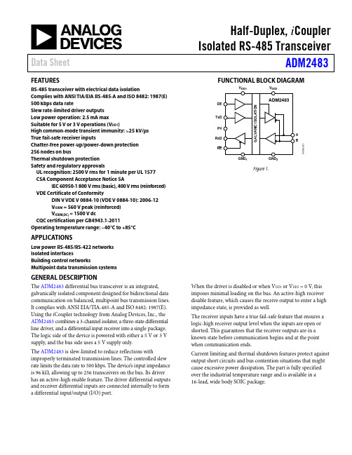

Declaration of Conformance – Test Summary per UN38.3.5Manufacturer:Inspired Energy, LLC.25440 NW 8th Place Newberry, FL 32669 USA(352) 472-4855 Email: *********************************Test Laboratory:Inspired Energy, LLC.25440 NW 8th Place Newberry, FL 32669 USA(352) 472-4855 Email: *********************************Test Report Number: 201106131Date of Test Report: Jun 13, 2011Description of Battery:Rechargeable Lithium Ion Battery containing 12 Moli IHR18650B 2.25Ah cells in 4S3P configuration648g, 14.4V, 6.6Ah, 95WhModel Number of Battery Tested: NL2024HD22Other Model Numbers Covered: NL2024XX22Tests Conducted and Results:Test # Description Date Tested Test resultT1 Altitude Simulation Apr 19, 2011 PASSEDT2 Thermal Cycling May 27, 2011 PASSEDT3 Vibration May 27, 2011 PASSEDT4 Shock May 27, 2011 PASSEDT5 Short Circuit Jun 1, 2011 PASSEDT6 Impact (Cell-Level test) Jan 9, 2009 PASSEDT7 Overcharge Jun 10, 2011 PASSEDT8 Forced Discharge (Cell-level test) Jan 9, 2009 PASSEDAssembled Battery Test Requirements [38.3.3 (f) and 38.3.3 (g)]: N/AStandard:ST/SG/AC.10/11/Rev.3: Amendments to the Third Revised Edition of the United Nations Recommendations on the Transport of Dangerous Goods Manual of Tests and Criteria Part III, sub-section 38.3Product Test Lab Manager: David W. HellriegelThe information contained within is provided for your information only. The information and recommendations set forth herein are made in good faith and are believed to be accurate as of the date of preparation. However, INSPIRED ENERGY, LLC. MAKES NO WARRANTY, EITHER EXPRESSED OR IMPLIED, WITH RESPECT TO THIS INFORMATION AND DISCLAIMS ALL LIABILITY FROM RELIANCE ON IT.。

Eaton MPN6403CEAXX2AEaton Magnum low voltage power circuit breaker, Magnum PXR,Double narrow frame, 4000 A (ABCABC), 65 kA, Three-pole,Drawout horizontal with motorized racking mounting, PXR20 LSItrip unitGeneral specificationsEaton Magnum low voltage power circuitbreakerMPN6403CEAXX2A78668959949216.3 in16.8 in24.9 in177 lbCE Marked NEMA Compliant CCC Marked SABA Listed KEMA CertifiedCSA CertifiedANSILloyd's Register Certified UL ListedABS CertifiedDNV GL CertifiedProduct Name Catalog NumberUPCProduct Length/Depth Product Height Product Width Product Weight Compliances CertificationsDouble narrow Three-pole Magnum PXRDouble narrow Magnum PXR20 LSIThree-pole4000 A65 kAIC65 kAIC4000 AZone selective interlocking application paper Magnum circuit breakers with Power Xpert Release trip units product aid Selevctive coordination application paper - IA0120000E3Magnum PXR and PD-SB double and double narrow frame UL Certificate of ComplianceMagnum PXR and PD-SB standard and narrow frame UL Certificate of ComplianceMicrosoft Word - Power Xpert Protection Manager Quick Start Guide.docxPower Xpert Release trip unit for Magnum PXR circuit breakers PXRFrame Number of poles TypeFrame Series Trip Type Number of poles Rated uninterrupted current (Iu)Interrupt rating Interrupt rating Rated uninterrupted current (Iu)Application notesBrochuresCatalogsCertification reportsManuals and user guidesEaton Corporation plc Eaton House30 Pembroke Road Dublin 4, Ireland © 2023 Eaton. All Rights Reserved. Eaton is a registered trademark.All other trademarks areproperty of their respectiveowners./socialmedia20/25 user manualMagnum PXR low voltage power circuit breakers user manual Power Xpert Protection Manager x64 22.6 1 Power Xpert Protection Manager x32 22.06 1 Eaton Specification Sheet - MPN6403CEAXX2A Low voltage circuit breakers guide spec Magnum PXR 20/25 electronic trip units time current curves Molded case and low-voltage power circuit breaker health Cyber security white paperSafer by design: arc energy reduction techniquesSoftware, firmware, and applications Specifications and datasheetsTime/current curvesWhite papers。

ENDURA C2 34 - 36" PARTS LISTIn the U.S.A., replacement parts may be ordered directly from MINN KOTA Parts Dept., 121 Power Dr., Mankato, MN 56002-8129. In Canada, parts may be ordered from any of the Canadian Authorized Service Centers. Visit for a current listing. Be sure to provide the MODEL and SERIAL number of your motor when ordering parts. Please use the correct part numbers from the parts list. Payment for any parts ordered from the MINN KOTA parts department may be by cash, personal check, Discover Card, Master Card or VISA. To order call 1-800-227-6433 or FAX 1-800-527-4464.Item Part Number Description12-100-285ARMATURE ASSEMBL Y 12v 3.252788-015RETAINING RING32-200-188HOUSING ASSEMBL Y CENTER 3.25 TXT42-300-142BRUSH END HOUSING ASSEMBL Y 3.25 SP.CO52-400-187PLAIN END HOUSING ASSEMBL Y 3.256880-003SEAL7880-006SEAL W/SHIELD8140-010BALL BEARING9188-052BRUSH ASSEMBL Y [2.EA]11738-030BRUSH PLA TE W/HOLDER 3.2514975-032SPRING-COMPRESSION [2.EA]17701-007O-RING- THRU BOLT [2.EA]18701-039O-RING MK40646019701-041O-RING20830-001SCREW- SELF THREAD 8-32X1.7 [2.EA]21830-062THRU BOLT 8-32X8.0 [2.EA]22990-067WASHER- STEEL THRUST23990-070WASHER- NYLATRON [2.EA]24144-049FLANGE BEARING (SERVICE ONL Y)252069271MOTOR ASSEMBL Y 12 V 3.25 5SPC TXT262032046TUBE, COMPOSITE 36”1378121PROP W/DRIVE PIN, WASHER, NUT KIT282061122PROPELLER 3.25 HUB DIA292151726WASHER- 5/16 STD SS302053101NUT-PROP NYLOCK (MED) SS312092600PIN-DRIVE2771818BRACKET & HINGE ASSEMBL Y (INCLUDES 32-43)2771910BRACKET ASSEMBL Y (INCLUDES 32, 34, 35)*322061910BRACKET332060510PIN-HINGE*342061300SCREW-CLAM [2.EA]*352011710WASHER-CLAMP SCREW [2.EA]362063605T-BAR, PLASTIC372062706SPRING- (T-BAR)* This item is part of an assembly. This item cannot be sold seperately due to machining and/or assembly that is required.2064975 rev A 7/10PARTS LIST (cont.)Item Part Number Description382067201LEVER-TILT BLACK 392061810HINGES-PLASTIC 402037301BUSHING-HINGE [2.EA]412062800TENSION BLOCK-SNAP IN 422011385SCREW, TENSION/KNOB 432060515PIN, TILT LEVER 442061520COLLAR-DEPTH 452011365SCREW-COLLAR/NEW KNOB 462020606LEADWIRE (14 GA) W/SPADE TERM 472020703SPADE TERMINAL 14GA HD [2.EA]482026300TIE WRAP 492062515CONTROL BOX 502060215CONTROL BOX COVER 512065705DECAL COVER ENDRUA C2 34522064028SWITCH-FWD/REV 5 SP 532033401SCREW-10-24 X 1-3/4542013110NUT -10-24 HEX 552012100SCREW-8-18 X 5/8 [6.EA]562990919INNER HANDLE ASSEMBL Y 572060405PIVOT, HANDLE 582012102SCREW 592990928OUTER HANDLE ASSEMBL Y 602060009FRONT BEARING 2883460SEAL AND O RING KITWIRING DIAGRAMSwitch。
