数字逻辑设计Digital Logic Design.pdf
- 格式:pdf
- 大小:939.28 KB
- 文档页数:53
![Lecture 1 Introduction to Digital Logic Design[第1讲介绍数字逻辑设计]](https://uimg.taocdn.com/0798f1fdad51f01dc381f126.webp)

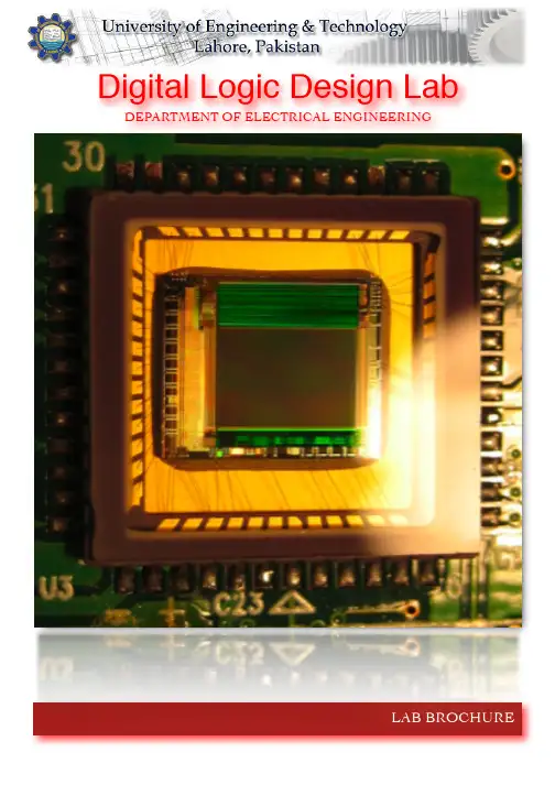
LAB BROCHUREDigital Logic Design Lab DEPARTMENT OF ELECTRICAL ENGINEERINGCONTENTS...................................................................................................................... Lab Venue 3............................................................................................. Lab Objectives & Courses 3 Lab Description & Experiments 4....................................................................................................................................................................................... Hardware Experiments 5 ....................................................................................................... Verilog Experiments 6 Lab Resources 7...............................................................................................................DLD Lab Venue: Computer Interfacing Lab First Floor, Electrical DepartmentLab VenueThe Digital Logic Design Lab (DLD Lab) is one of the most important and well equipped lab of the Department of Electrical Engineering at University of Engineering and Technology, Lahore. This lab is conducted at the Computer Interfacing Lab situated at the first floor of the Electrical Engineering Department.Scope of the LabThe DLD Lab is for undergraduate coursework related to the course EE131. It is one of the core modules of B. Sc. Electrical Engineering therefore the lab has a significant importance in the department.Related CoursesThis lab is designed such that thestudents get a hands on familiaritywith the concepts they come acrossin the course EE131 that is the DigitalSystems course. This is anundergraduate course which dealswith the basics of digital systemsdesign and is a core module of theB. Sc. Electrical Engineeringcoursework as it provides theprerequisites for advance courses indigital electronics. Because of thesignificance of this course the DLDLab has been carefully designed tomeet the course requirement.Brief Overview of the LabThe Lab is well equipped withboth hardware and software facilitiesrequired by the students to performthe necessary experiments designedfor this lab. Details of the labequipment has been discussed in aproceeding section.Experiments are designed insuch a way that the students becomewell aware of the concepts they learnin the theory sessions. A list ofexperiments that are conducted inthis lab has also been mentioned in aproceeding section.Experiments are related to bothdigital hardware and VerilogProgramming.Objectives & CoursesLab Description & ExperimentsLab DescriptionThe Experiments in the Lab have been divided into two major portions:•Hardware Labs•Hardware Description Language (Verilog) LabsHardware Labs have been designed to familiarize students with the Combinational Digital Logic Design and Sequential Digital Logic Design through the implementation of Digital Logic Circuits using ICs of basic logic gates and some simple digital logic circuits.HDL (Verilog) Labs havebeen designed tofamiliarize students with theHDL based Digital DesignFlow. These labs introducestudents with differentlevels of coding available inVerilog i.e. Gate level,Dataflow level andBehavioral level. Xilinx ISE7.1 tools have been used inthese labs. Finally, theskills learnt in the HDLlabs are employed toimplement some digitallogic circuits on Spartan-3FPGA, using Xilinx StarterKit Development Board.Expected OutcomesWith the help of the twothreads of the labmentioned above, studentswill have clearunderstanding of all thethree paradigms ofimplementation of digitallogic circuits:•Implementation usingICs for basic logic gatesand simple circuits•Implementationthrough the Developmentof Dedicated IC(ASIC)•Implementationthrough ReconfigurableLogic (i.e. FPGA)This makes studentsadept in basic conceptsinvolved in digital logicdesign. The lab contributesa lot to the basic learning ofdigital systems.This shows theindispensability of theDLD Lab.List of ExperimentsList of experiments isgiven on page 5 and 6. Asmentioned before the labhas two major portionstherefore there are two listsof experiments one relatedto the hardware labs andthe other related to thehardware descriptionlanguage (verilog) labs. Allthese experiments aremandatory and each lab isfollowed by speciallydesigned assignments.A Lab DemonstrationA Digital Chip (inside view)TITLE TOPICS1To Verify the Behavior of Logic Gates using Truth Table and Familiarization with Digital Integrated Circuits Basic Logic Gates, Truth Table, Integrated Circuits2Implementation of Boolean Function using Logic Gates and Introduction to Hierarchical Design of Digital Logic Circuits Boolean Functions,Boolean Algebra,Hierarchical Design of Digital Logic Circuits3Familiarization with the Different Portions of the Datasheet fora Digital IC and Using the Datasheet to Gather RelevantInformation to Utilize the IC as a Component in another DigitalLogic Circuit Datasheet of a Digital Logic IC, Hierarchical Design of Digital Logic Circuits4Implementation of 8 bit Binary Comparator using 4 bit Binary Comparators Binary Comparator,Hierarchical Design of Digital Logic Circuits5Implementation of 4bit into 3bit Binary Multiplier using 4bit Binary Adders Binary Multiplication,Hierarchical Design of Digital Logic Circuits6Implementation of BCD Adder using 4bit Binary Adders, 4 to 7 Segment Decoder and 2Digit 7 Segment Display BCD addition,Hierarchical Design of Digital Logic Circuits7Implementing a Full Adder using(a) Decoder(b) Multiplexer Implementation of Boolean function using Decoder,Implementation of Boolean function using Multiplexer8Flip Flops Different Types of Flip Flops9To study the fundamentals of basic counters and to construct various types of counters CountersHardware ExperimentsTITLE TOPICS1Introduction to HDL based Digital Design Methodology HDL based Digital Design Flow usingVerilog,Introduction to Outsourcing Business Model2Introduction to Basic Syntax of Verilog and Gate level Modelingthrough implementation of half adder at gate level and itssimulation using Xilinx ISE tools Basic Concepts of Verilog, Modules and Ports, Gatelevel coding in Verilog,3Introduction to the concepts of Instantiation and HierarchicalDesign in Verilog through the implementation of full adderusing the previously designed half adder modulesHierarchical Design in Verilog4Introduction to the Concept of Vectors and Introduction to Dataflow modeling through implementation of half adder andfull adder at dataflow level Vectors in Verilog,Dataflow level coding in Verilog5Consolidation of the concepts of Dataflow level modeling and Introduction to the concept of Synthesis by the CAD tool Dataflow level coding in Verilog, Logic Synthesis6Introduction to Behavioral modeling through implementation ofhalf adder and full adder at behavioral level.Behavioral level coding in Verilog7Introduction to if else statement and case statement inBehavioral modeling through implementation of Multiplexerif else and case statements in Verilog8Introduction to the Concepts of Sequential Circuit anda TestBench module (Stimulus Block)Sequential circuits in Verilog, Concept of Testbench module in Verilog9Behavioral Level Coding of Basic Sequential Circuits andConsolidation of the concepts of TestBench module (StimulusBlock)Sequential circuits in Verilog10Introduction to Field Programmable Gate Array(FPGA) and Steps involved in its Programming Need for Reconfigurable Logic, Xilinx ISE Tools for Programming the Xilinx FPGAsVerilog ExperimentsLab ResourcesHardware ResourcesThe lab is fully equipped with all the hardware required to conduct the above mentioned experiments. The hardware resources of the lab are:•Pentium-IV PCs (with MS WinXp OS)•Hardware trainers for logic circuit design and analysis•Electronic Chips of all digital gates•Spartan-III FPGA board kits•Power SuppliesThese resources allowthe students to have ahands on experience ofbasic digital logic designconcepts. This activitygreatly leverages what thestudents learn in the theorysessions.Software ResourcesThe lab also consists ofthe software resourcesrequired by the studentsnamely:•Veriwell•ModelSim•Xilinx IDE•MatlabSoftware resources areequally important ashardware resources are.These software resourcesare sufficient for thestudents to performexperiments. Thesesoftwares provide thestudents with thenecessary platform to workon HDL that is the Verilog.These softwares are alsorequired to work with thesophisticated hardwareslike Spartan-III FPGAboards.The lab has all theresources whether relatedto hardware or software sothat the students becomeadept in the basic field ofdigital electronics.Students areencouraged to use the labresources to performactivities andexperiments which helpthem strengthen theirconcepts.Lab StaffLike other labs of thedepartment there is atrained and able staffconsisting of skilled labtechnicians that take careof the lab equipment.They also guidestudents about handlingthe lab equipment and theprecautionary measuresrequired for the studentswhile working in the lab.A Digital Circuit BoardA SimulationDIGITAL LOGIC DESIGN LAB1st Floor, Department of Electrical Engineering UNIVERSITY OF ENGINEERING & TECHNOLOGY, LAHORE-54890, PAKISTAN..pkurl:Ph: + 92 42 9029229, Fax: + 92 42 9250224Computer Interfacing Lab。

数字逻辑设计课程设计一、教学目标本课程的教学目标是使学生掌握数字逻辑设计的基本概念、原理和方法,培养学生运用数字逻辑设计解决实际问题的能力。
1.掌握数字逻辑的基本概念和术语。
2.理解数字逻辑电路的组成和功能。
3.熟悉数字逻辑电路的设计方法和步骤。
4.了解数字逻辑电路的应用领域。
5.能够运用数字逻辑设计方法设计简单的数字电路。
6.能够使用电子设计自动化工具进行数字电路的设计和仿真。
7.能够分析数字电路的性能指标,并进行优化设计。
情感态度价值观目标:1.培养学生的创新意识和团队合作精神。
2.培养学生的动手能力和实践能力。
3.培养学生的科学思维和问题解决能力。
二、教学内容本课程的教学内容主要包括数字逻辑的基本概念、数字逻辑电路的组成、设计方法和步骤,以及数字逻辑电路的应用领域。
1.数字逻辑的基本概念:数字逻辑电路的定义、数字逻辑电路的种类、数字逻辑电路的特点。
2.数字逻辑电路的组成:逻辑门、逻辑电路、逻辑函数、逻辑代数。
3.数字逻辑电路的设计方法:组合逻辑电路设计、时序逻辑电路设计、数字电路的优化设计。
4.数字逻辑电路的应用领域:数字系统、数字电路在计算机中的应用、数字电路在其他领域的应用。
三、教学方法本课程的教学方法主要包括讲授法、讨论法、案例分析法、实验法等。
1.讲授法:通过教师的讲解,使学生掌握数字逻辑设计的基本概念和原理。
2.讨论法:通过小组讨论,培养学生的团队合作精神和创新意识。
3.案例分析法:通过分析实际案例,使学生了解数字逻辑电路的应用领域和设计方法。
4.实验法:通过动手实验,培养学生的实践能力和问题解决能力。
四、教学资源本课程的教学资源包括教材、参考书、多媒体资料、实验设备等。
1.教材:选用权威、实用的教材,如《数字逻辑设计》。
2.参考书:提供相关的参考书籍,如《数字电路与逻辑设计》。
3.多媒体资料:制作课件、教学视频等,以丰富教学手段和学生的学习体验。
4.实验设备:提供数字逻辑电路设计所需的实验设备,如逻辑门电路、数字电路仿真器等。

直接说正题,帮助一下刚刚入门的朋友们,也算是学习IC设计的一个总结吧。
一、首先要知道自己在干什么?数字电路(fpga/asic)设计就是逻辑电路的实现,这样子说太窄了,因为asic还有不少是模拟的,呵呵。
我们这里只讨论数字电路设计。
实际上就是如何把我们从课堂上学到的逻辑电路使用原理图(很少有人用这个拉),或者硬件描述语言(Verilog/VHDL)来实现,或许你觉得这太简单了,其实再复杂的设计也就是用逻辑门电路搭起来的。
你学习逻辑电路的时候或许会为卡拉图,触发器状态推倒公式而感到迷惑,但是其实有一点可以放心的是,实际设计中只要求你懂得接口时序和功能就可以了,用不着那么复杂得推倒公式,只要你能够用语言把逻辑关系表述清楚就可以了,具体这个逻辑关系采用什么门电路搭的,可以不关心,综合工具(synthesis tool)可以帮你处理。
当然你要知道基本门电路的功能,比如D触发器,与门,非门,或门等的功能(不说多的,两输入的还是比较简单的)。
---一句话,采用verilog或者VHDL描述设计对象的逻辑功能,这就是数字电路设计的任务!说到这里入门必须要两个基本功:逻辑电路基础,硬件描述语言。
有了这两个基本功,就算你其他都不会也能找到工作,呵呵,或许你会说,现在面试要问fpga,要问时序分析,有那么简单么?其实这些东西在你有了这两个基本功之后,其他的都可以慢慢学习。
注意硬件描述语言和逻辑电路的学习可以同步学习,而且要牢记,学习硬件描述语言进步取决于你对电路的理解和你对仿真器的使用。
为什么这样子说呢?因为硬件描述语言RTL(寄存器传输级)主要是用来给综合工具综合成电路的,所以要满足特定的coding style,这些coding style 将对应这特定的逻辑,比如时序电路应该怎么写,组合电路怎么写,这是有一定约束的,为此若你对逻辑电路比较熟悉,你就知道自己写代码大体综合后会采用什么门电路来组成;另外,写代码就要仿真,这是不可以避免的---不仿真,你怎么知道自己写的代码符合设计的要求呢?能够熟练使用仿真器,你就有了调试代码的基本能力,否则,写再多的代码也没有用。