海蒂诗MultiTech安装说明书
- 格式:pdf
- 大小:1.73 MB
- 文档页数:2

Installation Instructions Montageanleitung Montážní návodMonteringsvejledning Paigaldusjuhend AsennusohjeNotice de montageSzerelési útmutatóUputstvo za montažu Montagehandleiding Instructiuni de montajEN DE CZ DKEE FI FR HU HR NLROIstuzioni di montaggio Montavimo Instrukcijos Instalacijas instrukcija MonteringsanvisningInstrukcja montażu InstallationsanvisningИнструкция по монтажуInstrukcija za instalaciju Montážny návodNavodilo za montažo 安装说明书IT LT LV NO PL SE RU SRB SK SLO CN—1——2—L1.Installation and commissioning may only be carried out by authorized specialistsand wired in cordance with the latest IEE electrical regulations or the national standards.2.Mains power must be switched off before carrying out installation.3.The manufacturer, shall not be liable for any damage resulting from inappropriate modifications to the luminaire or faulty installation.4. Indoor use only.5. Caution, risk of electric shock.The control gear provides basic insulation between the LV supply and the control circuit.96630223 ANNA Suspension KitANNA LED PANELZumtobel LIGHTING GmbH Schweizer Strasse 30 A-6851 Dornbirn AUSTRIA URL:Safety Wire Installation ManualSuspension Kit User Manual96631383 ANNA 1200x300 Suspension KitSuspension Kit User Manual96630066ANNA LED Q5963750 840√√√96630067ANNA LED Q6223750 840622x622x8.5622x622x8.596630068ANNA LED Q5963750 840 E396630069ANNA LED Q5963400 83096630070ANNA LED Q6223400 83096631380ANNA LED 1200x300 4400 8401196x296x8.5Product DescriptionWattage PF InputSAP Code Dimension LxWxH(mm)Safety wireOperating temperature +5~+25°C-20~40°C -20~40°C 596x596x8.5AC220-240V50/60Hz 0.934W AC220-240V50/60Hz0.934W-20~40°C -20~40°C -20~40°C 596x596x8.5AC220-240V 50/60Hz0.934W 596x596x8.5AC220-240V 50/60Hz AC220-240V 50/60Hz AC220-240V 50/60Hz0.90.90.90.934W 34W40W L150096631381ANNA LED 1200x300 4000 830L1500 96630223ANNA Suspension Kit96631383ANNA 1200x300 Suspension Kit√√√622x622x8.5622x622x8.51196x296x8.5+5~+35°C-20~40°C -20~40°C -20~40°C AC220-240V50/60Hz AC220-240V50/60Hz0.934W-20~40°C -20~40°C596x596x8.5AC220-240V 50/60Hz0.934W596x596x8.5596x596x8.5AC220-240V 50/60Hz AC220-240V 50/60Hz AC220-240V 50/60Hz0.90.934W 34W 0.934W40W 96631113ANNA LED Q5963750 840 HFIX 96631114ANNA LED Q6223750 840 HFIX 96631115ANNA LED Q5963750 840 HFIX E3 96631116ANNA LED Q5963400 830 HFIX 96631117ANNA LED Q6223400 830 HFIX—3——4—Zumtobel LIGHTING GmbHSchweizer Strasse 30A-6851 Dornbirn AUSTRIA URL:IK02IP 20—44BO-LLHT04A002-01。

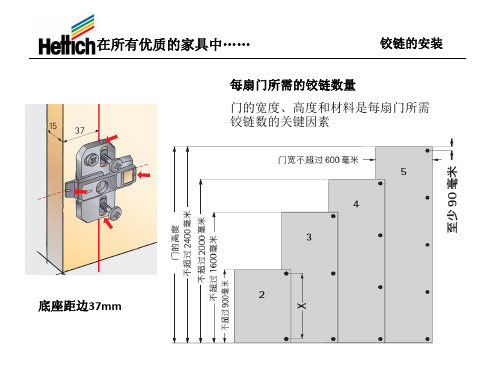
SIGNATURE SERIES扬声器安装说明重要安全信息必须按照以下说明安装此设备。
在开始安装本设备之前,请先断开船只的电源。
即表明音量太大。
尽量缩短以高音进行收听的时间。
如果出现耳鸣或听不清的情况,请停止收听,并检查您的听力。
为避免可能的人身伤害,务必始终在钻孔、切割或研磨时戴上防护眼镜、护耳用具和防尘面具。
注意钻孔或切割时,请始终检查表面反面的情况以避免船舶受损。
强烈建议由专业的安装人员安装音频系统,以确保最佳性能。
在开始安装之前,必须阅读所有安装说明。
如果在安装过程中遇到困难,请访问获得产品支持。
安装音频系统后,应当在最开始使用的几个小时内,使用低音量至中音量运行已连接的扬声器和重低音扬声器。
这有助于通过逐渐松弛新扬声器和重低音扬声器的运动部件(如锥形、弹波和环绕声等),从而改善整体音效。
•电钻•钻头(尺寸因表面材料而异)•用于切割表面材料的适用锯子或美工刀•十字螺丝刀•剥线钳•16 AWG(1.3 至 1.5 mm2)或更粗的船用级全镀锡铜扬声器导线您可以从 Fusion®或 Garmin®经销商处购买此电线:◦010-12899-00:7.62 米(25 英尺)◦010-12899-10:15.24 米(50 英尺)◦010-12899-20:100 米(328 英尺)•20 AWG(0.5 至 0.75 mm2)船用级全镀锡铜线,适用 LED 连接(仅限 LED 型号)。
• 3 A 直插式保险丝(仅限 LED 型号)•焊料和防水热缩管或防水、热缩、对接连接头(可选)•海事密封剂(可选)注:对于定制安装,可能还需要其他工具和材料。
安装注意事项将扬声器安装在露天或遇水区域中时,必须安装在垂直表面上。
如果将扬声器朝上安装在水平表面上,水可能会聚集在扬声器内部和周围,长此以往会造成损坏。
如果要将扬声器安装在船只外部,务必将其安装在不会被水淹没或者被船坞、桩基或其他设备损坏的、远高于吃水线的位置。


SMARTPUMP安装说明重要安全信息您有责任安全、谨慎地操作您的船只。
自动舵是一种可以增强船只操作能力的工具。
这并不能减轻您确保船只安全运作的责任。
避免导航危险,确保不会发生无人掌舵的状态。
总是为迅速重新手动控制您的船只做好准备。
注意为避免损坏船只,应由合格的海事安装人员安装自动舵系统。
必须具备具体的海洋转向及电气系统方面的知识,才能正确安装。
钻孔或切割时,请始终检查表面反面的情况以避免船舶受损。
此泵仅适用于 Garmin®自动舵系统。
尝试在其他系统中使用此泵可能会损坏系统、泵或船只。
此泵不得安装有无排气储液器的转向系统,否则会损坏泵。
安装泵前,必须确认船只操舵系统使用的是有排气装置的储液器。
通风孔通常位于最高的舵的加注口盖中。
如果您不清楚操舵系统是否带有排气装置,则应咨询舵的制造商或储液罐制造商进行验证。
泵必须安装在干燥位置,防止受到水和天气的影响。
SmartPump 根据自动舵系统的命令通过与液压转向系统交互来操控船的方向。
自动舵软件更新完成自动舵安装后,您应在执行配置过程之前更新软件。
如果您使用 Garmin 海图仪将自动舵系统连接至 NMEA 2000®网络,则可以使用海图仪更新软件。
如果您未使用 Garmin 海图仪将自动舵系统连接至 NMEA 2000 网络,则必须使用 NMEA 2000 网络更新器(单独出售)。
有关更新信息,请访问。
所需工具•护目镜•钻机和钻头•扳手•转矩扳手(如果为不平衡转向气缸配置泵)•钢丝钳/剥线钳•螺丝刀:十字头和一字头•扎线带•海洋腐蚀抑制剂喷雾•安装螺钉:泵套件包含安装螺钉,但如果随附的螺钉不适合安装表面,则您必须提供正确的螺钉类型•液压系统硬件 (液压系统注意事项, 第 3 页):◦液压软管,-4 [6 毫米(1/4英寸)ID] 或更高,带有机器压接或现场可更换配件,最小额定值为 1000 psi ◦液压 T 形接头◦液压截止阀◦螺纹密封剂,比如 Loctite® 567◦液压放气设备◦液压液安装注意事项泵必须安装在干燥位置,防止受到水和天气的影响。

TECH2 Series Installation ManualTechmation Co. Ltd.9F No. 529, Chung Cheng RoadHsin-Tien CityTaipei, Taiwan R.O.CTel : (02)2218-1686Fax : (02)2218-1766Email:*************************.tw********************.twNingbo, Mainland ChinaTel : (0574)87801426/87803022Fax : (0574)87807389Email:*********************.twHu-Men, Mainland ChinaTel : (0769)85182584Fax : (0769)85182587Email:********************.twCONTENTS1.TECH2 STANDARD USAGE (3)2.1T HERMOCOUPLE (7)2.2T EMPERATURE INCREASE CONTROLLER (8)3. SWITCHING POWER SUPPLY INSTALLATION (10)6. OPERATION PANEL INSTALLATION (25)8. PROPORTION V ALVE INSTALLATION (27)8.P OTENTIOMETER AND P RESSURE S ENSOR I NSTALLATION (28)9. MOTOR START CIRCUIT DIAGRAM (30)9.1Y-Δ START (30)9.2S TRAIT START DIAGRAM (31)1.TECH2 STANDARD USAGEThe installation for TECH2electricity control system is very simple, and the function of the control system is complete. Nevertheless, to prevent the life of the system end fast, the customer must follow the standard usage that is set by the company. Please refer statements below:1. The temperature for rack must be in the range of 0℃ ~ 40℃. The higher the temperature, the shorter thesystems life; and the differences of the potentiometer position can reach up to 0.8mm. It is recommended to fix a fan near the main controller switching power supply, and another one near the SSR.2.For temperature control, can use electromagnetic contactor or SSR (refer to the customers outfit). SSRheater sink should be not more than 65℃ or 75℃, and can’t use more than 5 minutes.3. Is required to use thermocouple type K. When installation, try not to tie together with strong electricparts. (This is regarding the accuracy and temperature stability)4. The fuse for SSR protection must be used according to the specification:a). power below 10A (consist of 10A) : use 10A fuse.b). power above 10A and below 20A (consist of 20A) : use 20A fuse.c). power above 20A : purchase according to the size of the fuse.5.Input voltage for switching power supply is 230V or 115V (there is a switch at the side of power supplyfor selecting). Please note that, if using voltage 115V/60HZ, should convert it from 220V to 110V with DC/DC converter.6.Our company is using a standard the fuse depends on the usage.7.Must strictly avoid the main CPU board from being damaged by water or oil.8.Transistor output board strictly prohibited 1 output point for 2 valves, but is allowed to connect a SSR.9.Our company is using a thin and clear panel screen. Therefore, it’s strictly prohibited to use highevaporate cleaner (etc. petrol, alcohol) to clean the screen. It is recommended to use kerosene and wax (the best suggestion) as cleanser.10.After the installation, must avoid any wire related to computer system broken (except thermocouple),and short circuit with machine outer case. Switching power case will have slightly electric leakage.Therefore, we insist to do ground connection.11.Proportion system normally can control the output of voltage or power (a standard tools for powercontroller). Power is set as 0.8A pressure and 0.7A flow.12.A standard SSR should be type NPN, using H24V and HCOM power supply system.13.The installation of potentiometer should avoid oil sludge pollution. If not, it will course the innerconnection of the potentiometer not sensitive or wire harden and broken.14.The location of the siren must be 20cm from the panel, 40cm from main controller.15. For the electromagnetic contactor that is used by the machine, must fix a spark quencher parallel to thecoil.16. Use SSR if is not using transistor output as controller, should fix a reverse diode parallel to the coil.17.There is a LCD on the operation panel. When installing, must be careful to avoid collide. If need toinstall or change the program (MMI display operation program), be careful of the high voltage at the back of panel when you open the cover.18. When fixing the power, please use iron board. If need to use bakelite plate, must make sure the groundconnection is done properly. This is to prevent electric leakage and electric static interference from damaging the PCB.This standard usage has to coordinate with the following installation manual. When the standard regulation is followed, this will guarantee the quality of the computer.MAIN CONTROLLER MEASUREMENT DRAW2. Temperature Controller InstallationIt consists of A. Thermowire and B. Temperature Increase Controller2.1 Thermocouple1. Thermocouple must be fixed on the Thermo Couple Input block, OIL as oil temperature. Follow the +veand –ve pole of 1-6 parts in thermocouple to fix the TC1-TC6. Don’t connect the thermocouple through many connectors. This will prevent from bad connection and affect the accuracy of the temperature. 2. When the remaining thermocouples are not used, please set the temperature parameter on the HMI to the not use selection (Refer to the HMI Operation Manual). 3. Please connect the thermocouple wire to the +ve and –ve pole to avoid the incorrect value on the controller that might lead the incorrect movement.(The draft below is one of the parts in the main controller)25P Cable (Double Shield)Thermo Couple InputFROM TMPEXTAT 1010-TPV +TPVFrom T1015 output11-7+CN13-8-OIL-6-3+6+9-9+OIL+4-2+TMPEXTA5+2-8+5-7-1+4+PCNX1PTC12.2 Temperature increase controllerTemperature increase controller uses A. SSR (Solid State Relay) or B. Magnetic Contactor2.2.1 SSRFrom the main controller RELAY OUTPUT connect straight to controller. Please be careful of the AC terminal and DC terminal. (DC terminal is the +ve and –ve pole, see below),2.2.2 Electromagnetic contactorIf you are using electromagnetic contactor as the temperature controller, please use RELAY to control the contactor. And fix a spark quencher parallel to the contactor coil. (Refer below)3. Switching Power Supply InstallationThe power supply for this system uses 3 groups of switch power supplies with 110V AC/220V AC options.A.For TECH2 main controllers, +5V, +12V, -12V DC/DC converter.For operation panel +5V, +12V DC/DC converter. Pressure proportional valve input voltage.B.For TECH2 controller VALVE output and LIMIT(SW-150-48), as picture below:C.For TECH2 controller flow proportional valve input voltage, (DCH40NB)as picture below:3.1 Reminder when using switching power1. If the switch power input is short; you must amend the switch power with:a. Varistor (20N 471K)b. Separate transformer: transformer voltage input could use many kind potential inputs and twopotential outputs (AC115V, AC230V,or AC115V/230V).c. EMI Filter (250V AC, 50/60Hz, 3A)Please refer to the suggestion below to prevent the power supply break down.2. FG for switching power supply must be ground connected. This is because, switching power supply might have slightly electric leakage, and this will disturb the system. Therefore, must prepare for ground connection no matter during fixing or using.(please refer chart below)4. The T1015AS transformer (for temperature controller) and the potentiometer are used together;Temperature controller uses yellow-green-yellow 3P wire, straight intoPCNXI(Beside thermocouple input terminal) at the main controller CPU board;Potentiometer controller uses blue-black-blue 3P wire straight into PCN1. (Refer to below):4. Operation Panel Q8 Color panel dimensionV8 Color panel dimensionM10M Color panel dimension5. Directional Valve and Output Installation1. This system provides 32 point DC24V director valve controller. The highest power each pointcan supply is 2A. It is not allowed to connect 2 directional valves at 1 point. If have to do so, please connect the RELAY to the controller and the shared point is H24V . If there is a load or misconnection of wire, switching power will be shut down automatically so it will not spoil the transistor. After repair the failure, please restart the switching power and the machine will run normally.VALVE OUTPUT2.RELAY output, main controller board provides 16 groups of RELAY contact point for customer usage. These include circuit for motor start , motor stop , Y-∆ converter , robot, heater controller etc.L 652(T C R 5)YL 1(T C R 6)S C53A53(T C R 4)54A54A C O 55AL 5L 2A C I N(T C R 1)L 455(T C R 2)(T C R 3)M O T .O F FL 3M O T .O N 52AL 7(T C R 7)L 8(T C R 9)L 9(T C R 8)6. Operation Panel Installation1. Please do not press on the flat cable at the back of the operation panel. It will cause the inner wire broken2. There is a DC/DC converter +5V , +12V circuit line in the PCB (PCB is on the operation panel) for LCD and HMI usage. Connect the DC24V (blue and black) to switching power supply.3. There are 2 white cables on the panel, must connect to setting key . If not, you can’t set the information. The 2 blue lines are for RESET, can be leaved on it self. You can fix the emergency stop as electrical emergency stop . (refer chart below)4. Please connect a line for ground connection from the panel to the copper board白白藍藍資料鎖定鍵緊急停鍵DATA SET EMERGENCY STOP BLUEWHITE WHITEBLUE資料重置DATA KEYRESET7. LIMIT Installation1.This system provides 32 input points.2.If using Limit, the shared power supply point is HCOM. When Limit works, HCOM will input signal.3.Power source for proximity sensor (type NPN) are H24V and HCOM, the signal for action is0V(HCOM).If there is other outer signal, must use low watt proximity sensor (This is because proximity sensor sink current is very low, can’t afford the high power device).If there is a COIL, must connect an opposite direction diode for protection.The arrangement is as below.8. Proportion Valve InstallationPCN4 3P connector (on the main controller CPU) is fixed to the switching power supply. On the other hand, CNDA2, CNDA3, CNDA4, CNDA5 outputs to proportion valves (manufactured by YUKEN, DIKEN etc.) are used to monitor the current meter at the proportion valve. To adjust the P 1-MAX, P 2-MIN, F 1-MAX and F 2-MIN rectificationF 2-F 2+P 2-P 2+F 1-F 1+P 1-P 1++24V C O M +H VP 1V +F 1V +C O M C O M P 2V +F 2V +CND1CND5CND4CND3CND2MIN P 2F 2P 1F 1MAX8. Potentiometer and Pressure Sensor InstallationA/D board is the interface for potentiometer. It converts the voltage, big and small changes (analog/similar) reading from potentiometer to digital signal, to enable CPU to read it. This A/D board can control 8 types of potentiometers, which is the injection, mold clamping, and lastly ejectionPotentiometerSIGNALIn the main controller, the potentiometer uses 3P power supply plugs. At the connector point as shown above, the PC board has 3P plugs and the 2nd pin must be connected to the signal output pin. Normally, the potentiometer prolongation has the biggest value and the back contract has the smallest value. If the direction reverses, the potentiometer 1st and 3rd pin of the plug will be immediately changed (it changes the +ve and – ve pole). Keep in mind not to disconnect the signal; else it will cause the damage to PC board or potentiometer.Please refer to operation manual for potentiometer reset. Choose the length of potentiometer longer than the machine length to avoid being pulled apart.9. Motor Start Circuit Diagram 9.1 Y-Δ startTECH2 Series Installation Manual 9.2 Strait start diagramTechmation Co., Ltd. 31。
HAYWARD INDUSTRIAL PRODUCTSBUTTERFLY VALVEINSTALLATION, OPERATION AND MAINTENANCE INSTRUCTIONS PLEASE READ THE FOLLOWING INFORMATION PRIOR TO INSTALLING AND USING HAYWARD VALVES, STRAINERS, FILTERS, AND OTHER ASSOCIATED PRODUCTS. FAILURE TO FOLLOW THESE INSTRUCTIONS MAY RESULT IN SERIOUS INJURY.1.Hayward guarantees its products against defective material and workmanship only. Hayward assumes no responsibility for damage or injuries resulting fromimproper installation, misapplication, or abuse of any product.2.Hayward assumes no responsibility for damage or injury resulting from chemical incompatibility between its products and the process fluids to which they aresubjected. Compatibility charts provided in Hayward literature are based on ambient temperatures of 70º F and are for reference only. Customer should always test to determine application suitability.3.Consult Hayward literature to determine operating pressure and temperature limitations before installing any Hayward product. Note that the maximumrecommended fluid velocity through any Hayward product is eight feet per second. Higher flow rates can result in possible damage due to the water hammer effect. Also note that maximum operating pressure is dependent upon material selection as well as operating temperature.4.Hayward products are designed primarily for use with non-compressible liquids. They should NEVER be used or tested with compressible fluids such ascompressed air or nitrogen.5.Systems should always be depressurized and drained prior to installing or maintaining Hayward products.6.Temperature effect on piping systems should always be considered when the systems are initially designed. Piping systems must be designed and supported toprevent excess mechanical loading on Hayward equipment due to system misalignment, weight, shock, vibration, and the effects of thermal expansion and contraction.7.Because PVC and CPVC plastic products become brittle below 40º F, Hayward recommends caution in their installation and use below this temperature.8.Published operating torque requirements are based upon testing of new valves using clean water at 70º F. Valve torque is affected by many factors including fluidchemistry, viscosity, flow rate, and temperature. These should be considered when sizing electric or pneumatic actuators.9.Due to differential thermal expansion rates between metal and plastic, transmittal of pipe vibration, and pipe loading forces DIRECT INSTALLATION OFMETAL PIPE INTO PLASTIC CONNECTIONS IS NOT RECOMMENDED. Wherever installation of plastic valves into metal piping systems is necessary, it is recommended that at least 10 pipe diameter in length of plastic pipe be installed upstream and downstream of the plastic valve to compensate for the factors mentioned above.INSTALLATIONHayward Butterfly Valves should be installed between two pipe flanges. In dead end service, it is recommended they be installed between one pipe flange and a downstream companion or blind flange. The use of additional gaskets is not necessary and not recommended.When installed between two existing flanges, the flanges should be separated to provide clearance on the face to face of the valve. This will prevent the valve sealing surfaces from distortion during installation. Pipe flanges should be clean and, free of debris including old gasket material. A light coating of a lubricant such as “Non-Fluid Oil” #666 applied to the flange sealing-surface will aid in installation.Hayward Butterfly Valves are designed for use with all pipe flanges that have bores equal to or larger than Schedule 80 pipe (Schedule 40 pipe for 14”-24” valve) as listed below. The inside of the pipe flange must be chamfered at a 45 degree angle to a diameter listed if the inside bore is smaller than listed. Sharp edges and burrs must be removed.Valves can be opened to approximately 15º when installed. Do not open fully during installation to prevent damage to the edge of the disc by the mating flanges. Install the valves using well-lubricated studs or bolts and nuts. For plastic flanges metal washers are recommended between nut/bolt head and pipe flange. With a torque wrench, uniformly tighten nut to approximately 10 foot pounds in an alternating sequence, diametrically opposed to the previously tightened nut. Final tightening should be performed in the same sequence following the recommended torque in the following chart.For plastic Schedule 80 pipe the maximum allowable displacement is 1/16” off center in any direction. Maximum angular misalignment of 1/32” is allowable.Normal pipe hanger spacing is recommended. Do not allow valve to support the weight of pipe. When using pneumatic or electric actuators, additional support directly to the actuator is recommended.RECOMMENDED FLANGE BOLT TORQUE FOR BUTTERFLY VALVESSize NominalMinimumPipe / FlangeBore (in.)Stud Dia (in.)xLength (in.)Bolt Dia (in.)ThreadFlat Face Type FlangeTorqueFt * Lb.Van-Stone Type FlangeTorqueFt * Lb.1 1/2” 1.45 1/2 x 4.50 1/2 - 13 UNC 10-15 5-10 2” 1.88 5/8 x 4.50 5/8 - 11 UNC 15-25 10-20 3” 2.83 5/8 x 5.00 5/8 - 11 UNC 20-25 10-20 4” 3.75 5/8 x 6.00 5/8 - 11 UNC 20-25 10-20 6” 5.68 3/4 x 6.75 3/4 - 10 UNC 30-40 10-20 8” 7.54 3/4 x 7.50 3/4 - 10 UNC 30-40 20-30 10” 9.47 7/8 x 10.25 7/8 - 9 UNC 50-60 40-50 12” 11.27 7/8 x 11.50 7/8 - 9 UNC 50-60 40-50 14” 13.12 1 x 10.25 1 - 8 UNC 100 N/A 16” 14.35 1 x 12.75 1 - 8 UNC 100 N/A 18” 16.50 1-1/8 x 13.25 1-1/8 - 7 UNC 100 N/A 20” 18.50 1-1/8 x 14.50 1-1/8 - 7 UNC 100 N/A 24” 22.25 1-1/4 x 14.75 1-1/4 - 7 UNC 100 N/AOPERATIONWhen installation is complete, check for proper alignment. Fully open and close the valve 3 or 4 times. With a lever installed, fully squeeze the handle and hold in for the full stroke 90º stroke of the lever. For optimum operation the lever handle should be held up until full stroke of valve is reached. The handle should be relaxed only at end of stroke.Maximum operation pressure at 70º F is 150 PSI for 2”-10”, 100 PSI for 12”-14”, 86 PSI for 16”, 72 PSI for 18”, and 51 PSI for 20”-24” valves. MAINTENANCE & DISASSEMBLY OF VALVEI.Minimal valve maintenance is required.II.Actuator Assembly: Actuators can be removed and installed without removing valve from the line. The line should be depressurized before any actuator is removed.。
Area of ApplicationESSVE Steel anchor is designed for installa-tion in all types of board materials.DescriptionThe steel anchor is available in three variants as standard, two with screws and one with a hook. All screw heads are fitted with combi-cross and support 5-35 mm board thickness. Screw and boom are made of bright zinc plated steel and the hook is made of chrome-plated steel.InstallationSpecificationSteel anchor, bright zinc platedSmall packageBulk packagesInstallation instruction1. Drill the hole. Take it easy so as not to da-mage the drywall on the back/around the exit hole. The drill dia-meter is selected ac-cording to Technical data.2. Before the Steel an-chor is pressed into the drill hole, fold over the toggle disc so that it is positioned parallel to the screw. This is done by locking the toggle disc’s prong in the guide groove at the rear of the disc which comes on the out-side of the wall.3. When the Steel anchor is in position in the drill hole, push the screw so that the toggle disc loo-sens from the guide groo-ve and “folds out" on the rear of the wall.4. Unscrew the screw. Hang up the object and screw up the object so that the toggle disc locks the installation. The in-stallation is finished.Material SteelSurface finishBright zinc platedItem no.DesignationDrill mmQty/pack.Pack./large pack.511631TPP 10×M4S (screw)10210511633TPP 10×M4K (hook)10210511635TPP 13×M5S (screw)13210Item no.DesignationDrill mm Qty/pack.Item code1200023TPP 10×M4S 101500B 1200221TPP 10×M4K101000B 1200412TPP 13×M5S131500BB = Order itemItem no.Designation Screw Ø x length mm Suitable board thick-nessmmMax. object thickness for board thick-ness 13 mm2x13 mm 511631TPP 10×M4S M4×559-303724511633TPP 10×M4K M4×50 (hook)10-26511635TPP 13×M5SM5×659-354734Practical load capacityDesignation mm Drywall thicknessmmTensile load (N)kgShear load (V)kgTPP 10×M4S132035 TPP 10×M4S2×133055 TPP 10×M4K132035 TPP 10×M4K2×133055 TPP 13×M5S132545 TPP 13×M5S2×134565 Safety factor: 3.0。