FreeForm分模流程-FreeForm Modeling Plus软件教程
- 格式:pdf
- 大小:8.24 MB
- 文档页数:28

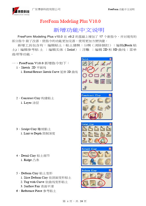
FreeForm Modeling Plus V11新增功能中文说明概述:FreeForm Modeling Plus V11.0 版本新增了15项新功能(下图以红线圈起的图标为完全新功能),其次在原有指令的基础上加强并改进了功能,使新版本使用更方便,快捷,整体造型能力更加强大。
一、新增指令:1、 Construct Claya、curve network to clay(依曲线网格转换黏土);b、Pattern piece(依曲线复制物件);c、Extrude to plane(延伸黏土至2D平面);2、 Sculpt Claya、Smooth with Curve(依曲面填充黏土)3、 Deform Claya、Lattice Deform(依网格框架变形黏土);4、Select/Move Claya、Select Objects with box框选物件;b、Align to path(使黏土依路径排列);c、Select clay with Patch(依曲面选择黏土)5、 Patches/Solidsa 、Create Ring Patch(依两条环形曲线建曲面);b 、Curve network to Solid(依曲线网格转换实体);6、Analysis Toolsa 、Analysze Fit (分析黏土贴附程度); b、Analysze Inter s ection (分析相交黏土); c 、Analysze Thickness (分析黏土厚度)d 、Dimensional Bounding Box (显示黏土的空间边界);e 、Ruler(3D 测试);二、新增指令功能详细说明:1、curve network to clay(依曲线网格转换黏土);2、Pattern piece(依曲线复制物件)微调旋转物体方向移动锁定轴向从曲线端点排列最后一个物件的比例生成新的图层旋转方式选择球珠和3D 线,设定球珠数量。

Mold DemoCreating Parting Line: Load the included Vampire Boy model.Go to Tab > Moldable PartCreate a parting line curve by activating the mold toolbar feature by selecting theMoldable Part tab. Then click on the Parting Line Curve icon on the toolbar andFreeform Mold Demo -1-click on the Show Parting Line Color icon to show the parting line. The arrow on the screen indicates the mold pull direction. You can change the direction by clicking onthe Set Direction icon to check the best parting line solution. Once everything is set, click on Apply to create the parting line curve.The parting line curve direction is already set for this model, but be sure the parting line draft angle is set to zero. To check if the draft angle is set to zero for this evaluation, go to Tools > Option > Parting line draft angle. For using the Parting Line tool, always set the draft to zero so that you will get a clear blue line. If the draft is not set to zero, the parting line curve will not be created in the correct location.Currently, the mold pull direction is already set correctly. If you want to show people the different pull direction, click on the Set Direction icon to change the setting.Showing Curvature PlotFreeform Mold Demo -2-The parting line curve is very dense and trying to pick up all the details necessary. If you want to look at the level of quality of the parting line curve, you can turn on the curvature plot and create a curvature plot of each curve. Go to:View > Design Curves -> Create Curvature Plots. Then click on the parting line curves on the model. By default, the plot is set in 2D to show the noise in Z direction only; you can also set to show the noise in X and Y direction by changing the 2D Curvature icon to 3D Curvature icon on the Dynabar. [as shown below]2D curvature plot showing on noise in Z directionFreeform Mold Demo -3-3D curvature plot showing noise in X and Y directionIn most cases, you will only want to use the 2D curvature plot in the Z direction. The number shown on the curvature plot indicates the minimum radius curvature of the curve. This number can be used to determine the tool size for machining in the future. To find the tool radius, simply take the inverse of the curvature value. The equation used in this calculation is shown below:C = 1/R ; C = curvature, R = radiusEditing Parting Line CurveFreeform Mold Demo -4-machining. To avoid this problem, I am going to smooth the parting line curve. Tosmooth the parting line curve, click on the Select icon on the toolbar and then clickon the parting line curve. Change the number on the Points box to reduce thenumber of points on the curve. In most cases, you can reduce the number of point by halfthen refit it. Be aware that it may have drifted from sharp details in the XY plane.Usually, after reducing the points on the parting line, the parting line will likely still be very close to the original parting line. However it does not work for every case. In most situations, you can just reduce the points and refit it just for demo purposes.Now I will refit the parting line curve by clicking on the Fit CurveFreeform Mold Demo -5-to Clay tool under the same flyout as the Parting Line Curve tool. Then click on the parting line curve. Refitting the curve will remove the curvature plot information because the refitted curve is actually a new curve. Therefore, you have to put the curvature plot back on to see the new result. Now you can see that the refitted curves have a low curvature and noise.You can also use the Smooth Curve tool under the Parting Line Curve tool to smooth out the curves. After you are satisfied with the result, you can turn off the curvature plot.Fixing DraftFor this model, there is a draft problem. To demonstrate the draft-fixing feature, youFreeform Mold Demo -6-should point out some draft problems on the model. Indicate the areas behind the nose and the teeth (Create Parting Line actually surrounded these areas with curves, which can be deleted at this time.)The next thing to do is to fix draft. As you can see on the screen, the nose and the tooth have a draft issue. To correct the problem, I can either add material or remove material to correct the problem under the Draft option.Go back to create moldable part and then select Draft tool on the toolbar. Then click on the parting line. The problem areas are shown in blue. Now I want to add material behind the nose to the fix the draft instead of chopping off the nose to fix the draft. So I click on the Add Clay , but hold to the parting line by clicking thePreserver Parting line icon then click Apply.The changes on the model should be very quick, so you can say a few words or gesturing with your hands, then the changes should be done. The fixed model is shown below.Freeform Mold Demo -7-Shelling The ModelClick on the “d” key to show the model in See Through mode, and indicate that it is a solid model. Click the “d” key once more to return to an opaque view.Now you can shell the model. Click on Shell on the toolbar. For this model, I want a 4mm shell. Then change the number in the Shell Thickness box on the dynabarto 4 and click Apply.Freeform Mold Demo -8-The shelling process should be done very quickly. While waiting for the model to be shelled, you can talk about the benefit of this feature. After the shell is complete, click on “d” on the keyboard again to activate the dotted mode for showing the part thickness.Click “d” to change to dotted mode to show part thicknessYou can check the part thickness by using the ruler feature. Go to Tools > Ruler or click“r” on the keyboard to activate the ruler feature. Then select Measure Thicknessicon on the Dynabar and measure the part thickness.Freeform Mold Demo -9-Creating Split JointFor better visual, turn off the clay by clicking on Blank Clay icon. The resulting screen is shown above. By turning off the clay, you can see the glue joint that you will create on the screen.Now I want to be able to create the shiplap joint. I go down to the Split Joint tool and pick on the curve on the screen. It will create a butt joint by default first (shown below) then I will create a shiplap joint on the modelFreeform Mold Demo -10-.After selecting the curve on the screen, a butt joint will be created. The creation of butt joint will not fail on this model. The shiplap joint properties box will pop up automatically when the butt joint is created.On the ShipLap Joint Properties box, set the values on the boxes to:-Offset value to 2mm because it’s a 4mm shiplap-Depth value to 2.5mm, just high enough that people can see the difference -Angle value to 5 degree so that it looks like in a angleFreeform Mold Demo -11-Ensure the Modify Region icon is selected on the dynabar then click on any two points on the outside curve of the model to define the region of the joint then click on any place on the curve within the region to create the split joint (as shown above).For the demo, create shiplap joint at only one place because for every place you do, you have to be able to select the inside curve of the split joint in the middle of the demo when you are doing Make Part and Make Insert. Therefore, to shorten the demo time and keep the audience’s attention, avoid creating more than one split joint.Next you want to show the Groove split joint feature, make an undo after the shiplap joint is created. Then select Groove Joint icon and the Groove Joint Properties box will appear.Freeform Mold Demo -12-Make sure the sum of the Offset value and the Width value does not exceed the width of the split joint, which is 4mm in this case. Otherwise, you will receive an error message. Once the values are entered, ensure the Create Split Joint icon is selected on the dynabar to create a groove joint on the entire curve. Then select the curve on the screen and a Groove Joint will be created (shown as below)Creating the groove joint for the demo is easier for the Make Part step later in the demo because you don’t have to pick the separate section all the way around the curve.Freeform Mold Demo -13-Freeform Mold Demo -14-Making PartNow I will separate the model into 2 parts, part 1 and part 2. I go to the Make Particon on the toolbar. Then select the Split Curve icon on the dynabar and click on the first split joint then the second split joint of the part. Next I click on the Part 1 Sideicon and click on the outside of the model(the face in this example) to select what is going to the part 1.When selecting the part 1 side, uncheck the Blank Clay to show the whole piece of clay. It’s easier in this way.Freeform Mold Demo -15-The first split joint is the outside curve of the part and the second split joint is the inside curve of the partThe first split joint is highlighted inFreeform Mold Demo -16-The second split joint is highlighted in green as shown on the rightnow look at the other part by selecting Work on Part of the other part in the Object List.Freeform Mold Demo -17-To turn on the object list, either click “o” on the keyboard or go to View > Object listOn the Object List, click on the part icon, and select Work On Part option to select the part that you want to work on.For the rest of the demo, we will work on one part of the model, Part 1 the face, though the other Part 2 can be done in a similar way.Freeform Mold Demo -18-Creating Mold InsertSo the next thing I will create an extent for the part, that is defining the actual mold insert dimensions, and create parting surfaces for the model.The extents can be resized to any dimension you need to fit into the mold. To resize it, you go to the set extents option (which is usually active when first entering the Mold Insert tab) and enter the XYZ values for the extents.To resize the extent, click on Create Mold Insert tab on the top of the workspace thenselect Mold Insert Properties and click on Set Extents icon on the Dynabar. Enter the desired dimension for the extent on the X,Y,Z boxes. For the demo, show people that the extent can be changed and set the numbers in the X,Y,Z boxes to a reasonable numbers. The following numbers are used for this demo:+X = 100.00, -X = -100.00+Y = 150.00, -Y = -150.00Freeform Mold Demo -19-+Z = 100.00, -Z = -100.00Freeform Mold Demo -20-Creating Extruded Parting SurfaceNext I will create the parting surfaces for the part. I go to the Extrude Parting Surfacetool then pick on two places on the curve to define the boundary. When you are picking the points to define the boundary, you don’t have to pick on the points, you can pick anywhere on the curve. The extruded surface can be created in a 45 degree angle. When extruding the surfaces from this example, extrude the surfaces perpendicularly from the form. For example, extrude it in a horizontal or vertical direction.Freeform Mold Demo -21-Creating Insert BlocksAfter the parting surface is completed, I will create a core insert block and a cavity insert blocks for the part. This can be done in a few steps.First I go to the Make Insert Blocks tool on the toolbar. Second, I pick the edge of the parting surface and the parting line. Finally, I select the side for the cavity block. To create insert blocks for the part:-Click on Parting Surface Curve icon on the Dynabar and select the edge of the extruded surface-Then select the parting line of the model (as shown below in green)Freeform Mold Demo -22--Click on Cavity Side icon on the dynabar and select the cavity side of the model.-Once the cavity side is selected, a plane will appear on the screen to represent the bottom of the cavity block.o Notes: Don’t zoom to close to the model; otherwise you will not be able to see the plane.o Notes: If you selected the top part as the cavity side, then the plane should be placed on the topside or on the bottom side if the bottom part isselected as the cavity side.- A window will pop up and asks if the plane is placed correctly, click “Yes” if the plane location is correct or “No” if the plane location is incorrect…Freeform Mold Demo -23-shown below)…Freeform Mold Demo -24-From here, I have two insert blocks, one for the core and the other one for the cavity. I can look at either one of the blocks by selecting it on the Object List.To look at the core block:-Turn on the object list and click on the core mold insert icon, and select Work On Component option-This will hide the cavity side component automatically.Freeform Mold Demo -25-Freeform Mold Demo -26-You can turn off “See Through Clay” option by View > Design Curve > See Through Clay for people easier to see to blockFreeform Mold Demo -27-Reverse Engineering the Core FaceThe next thing I will do is to create patch surface for the core. After I create the patches, I can export the file to other CAD software to build other components on the mold insert such as runners systems, water lines, sprues, and ejection pins, etc. To create the patch, I draw curves that defined the patch boundary on the core. Then using the Patch toolon the toolbar to create the batch surfaces for the core.Freeform Mold Demo -28-To draw curves defining the patch boundary on the core:-Select Draw tool under Parting Line tool-Ensure the Fit on Create icon is selected on the dynabaro Notes: DO NOT select Split on Create icon on the dynabar because it will destroy the surfaces by separating the curve into two-Turn on See Through Clay option by: View > Design Curves > See Through Clay (if you find it to be easier).-Start drawing curve on the model to cover up the entire core (as shown above)Freeform Mold Demo -29-To create patches on the core surface:-Once the curves are drawn on the surface, select the Patch tool-Ensure Fit to Clay and Manual Boundary Select icons are selected on the dynabaro Notes: Selecting the Fit to Clay icon will create patches that are more tightly fitted on the clay surface than using the Fit to Boundary icon . -Click on the curves in sequence to define the boundary of the patch. Once you are done the patches, go to the object list and folder the patches you create and label the folder something meaningful. You will need to refer to this folder later.Freeform Mold Demo -30-Exporting IGESOnce the Core side of Part 1 is patched, it can be exported as an IGES file for further modification in other CAD software.To export an IGES file of the Core side:Go to File > Export > Curves and Patches, then check the following information in the dialog box that appears:Freeform Mold Demo -31-…which will write an IGES file for CAD import. To export an STLfile of each of the blocks of the insert, for rapid prototyping:For the core, turn off the display of all Clay and Curves using the lower left display control:Then go to File > Export > Model, then, it will export the patches which will be subdivided to create polygons out of the patches.Usually, the default has adequate details when exporting the STL polygon file but if you want more detail, go to Patch Display Properties under the Blank Patches icon onFreeform Mold Demo -32-the Dynabar.Freeform Mold Demo -33-Changing the Display Resolution to High in thePatch Display Properties will give you a muchfiner tessellation of the patches.You can verify your results by reading the fileback in as an STL import and preview (but don’tkeep it, just preview it as below…Note: When exporting the Cavity side, you don’t want the Split Joint patches or the core face patches visible. On the Object list, do a “work on component” on the cavity component first, then hide the Split Joint Curves and Split Joint Patches folders as shown on the right. Find the folder you created for the Core face reverse engineering patches and hide it as well.Creating ElectrodeCreating electrode off the cavity is not something that is automatically created but it is not too difficult to do. First you want to turn off the surfaces and build a plane to project the parting line onto the plane. Then draw a line to connect the curves and create a patch for the side. Once the patch is created, export it as an electrode.To Create Electrode Off the Back Cavity Block:Go to the Object list then turn off the surfaces of the core and cavity blocks and the parting surfaces as shown below.Then select New Plane/Sketch on the toolbar to create a plane. The distance between the part and the plane is equal to the distance of the side of the electrode.Select Project Curve to Plane from the flyout of the Parting line curve tool on the toolbar. Then click on the parting line curves and touch the plane. The curves will then be projected onto the plane (as shown below). Once the curve is projected, you can hide the plane on the object list.Freeform Mold Demo -34-Next select Draw from the Parting line curve tool on the toolbar. Make sure the Fit on Create icon on the dynabar is deselected because you want to make a square patch. Then draw a line connected the parting line and the projected parting line.For this model, a patch can be built with only two main curve segments (as shown below)Freeform Mold Demo -35-Freeform Mold Demo -36-dynabar so that a straight extrusion can be created. Then select the curves in sequence to create the patches (as shown below)Once the side patches are created, you can make a patch for the back but for electrodes the back patch is not required. Then export it as an STL file for tooling the electrode.。


玩具建构练习(使用2D影像)01.开启新档。
02.从File/Import/Image输入2D影像图文件的前视图(Front.jpg)。
03.按F3切换至侧视视角。
04.从File/Import/Image输入2D影像图文件的侧视图(Side.jpg)。
05.点选对象清单(Object List)中的侧视图以进入绘图模式,并调整影像的尺寸及位置。
06.点选前视图并进入绘图模式。
07.绘制中轴线和头部的断面线。
08.点选Spin功能,选择断面线,再选择中轴线将小恐龙的头部制作出来。
09.开启对象清单(Object List),将黏土粗糙度调整为Add Detail。
10.开启对象清单(Object List),复制前视图,并关闭原始的前视图。
11.使用Edit Plane将绘图板往前移动,以避免被头部的模型遮住。
12.点选Sketch On进入绘图模式,并绘制出鼻子的轮廓线。
13.点选Wire Cut功能,并点选鼻子的轮廓线,建构大体形状。
14.使用Inflate功能,依据侧视图制作出鼻子的外观。
15.使用Smooth顺化工具,将鼻子和头部间进行顺化。
16.开启对象清单(Object List),将黏土粗糙度调整为Add FineDetail。
17.点选Sketch On进入绘图模式,并绘制出鼻孔的轮廓线。
18.使用Project Sketch将2D线段投影在模型上。
19.使用Tug Area点选线段,以调整出所需的形状。
20.使用Add Clay制作牙齿。
※选择Pieces/New Piece/Start with Empty Piece,将对象产生在另外的图层里。
22.使用Edit Plane将绘图板移动至模型中央位置。
23.点选Sketch On进入绘图模式,并绘制出犄角的轮廓线。
的外观。
※选择Pieces/New Piece/Start with EmptyPiece,将对象产生在另外的图层里。
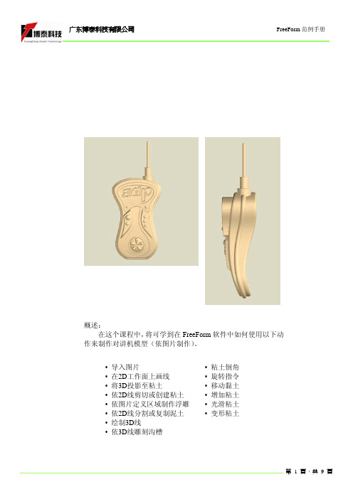
概述:
在这个课程中,将可学到在FreeForm 软件中如何使用以下动作来制作对讲机模型(依图片制作)。
• 导入图片
• 在2D 工作面上画线 • 将3D 投影至粘土
• 依2D 线剪切或创建粘土 • 依图片定义区域制作浮雕 • 依2D 线分割或复制泥土 • 绘制3D 线
• 依3D 线雕刻沟槽
• 粘土倒角 • 旋转指令 • 移动黏土 • 增加粘土 • 光滑粘土 • 变形粘土
点击Sketch on
,
Select Now
,
,Paste as new piece
,
位中心,同理再选择
Move only
Symmetry off
选取图片后,会弹出图片调整对话框。
输入花纹深度2.0mm,选择Raise 凸起来。
Activate
贴铺面完成后需点击执行
*执行Wire Cut指令建构Piece 4的
雏形.选择Create Inside新建粘土.
*执行Deform指令来变形粘土. 选
Ice-cream Cone
,
,To center 位中心,同理再
(Combine Into).
Create Inside
1,移动平面至另一边后
Round。
戒指建构练习(使用2D影像)
01.开启新档。
02.从File/Import/Image输入2D
影像图文件的前视图
(Front.jpg)。
03.按F5切换至上视视角。
04.从File/Import/Image输入2D
影像图文件的侧视图
(Top.jpg)。
05.点选对象清单(Object List)中
的上视图以进入绘图模式,
并调整影像的尺寸及位置。
06.点选Edit Plane后,选择要操
作的平面,点选Sketch
on plane(K)进入2D画线功能07.在Top平面上绘制戒环的断
面线和中轴线。
08.将对象精度设定为Add
Detail。
09.使用Spin clay旋转功能,将
戒环基本形状制作出来。
※选择轮廓线,再选择中心轴,
执行Create Inside即可。
10.按F2切换至前视图。
11.点选Edit Plane将前视图移
动至正确位置。
>>>
1.选择全部。
2.复制戒环。
3.
执行
先描出封闭特征线。
This document presents a speci c work ow describing how to create a complex parting surface intended for molding and manufacture processing and output. By using digital clay as a base for the construction method we will create a NURBS parting surface as well as a NURBS positive of the gurine part below intended for molding. These two components will then be exported to a post-processing CAD package where insert blocks for a precise negative cavity clamshell mold will be engineered.by: Steve BrunoPositive DigitalClay PartComplex NURBSParting SurfaceNURBS ClamshellMold Insert BlocksHere we have an initial clay model intended for manufacture. To begin the mold creation process we need to determine an initial parting solution with Parting Line Colors to make viewable any issues that will arise in manufacture such as undercuts. Notice on the nose and behind the teeth where there are extra blue patches which illus-trate undercut issues.Create a parting line using the Parting Line Curve tool in the Mold toolbar. Keep the main parting line that travels along the middle of the entire part and delete the extra lines that were created due to the undercut issues explained previously. We only want ONE continuous parting line.Here we t the parting line to the surface of the clay using the Fit Curve tool. This initial parting line is only being created as a guide to set up our parting surface so it does not need to be 100% accurate.Use the Fix Draft tool to add a draft angle and add clay to the undercut problem areas. Notice below the added clay to the back of the teeth on the model. There was also minimal clay added to the nose area as well.Using the Smooth tool to smooth out the transition of the parting line area on the clay model.When smoothing and editing the part post-Fix Draft make sure Show Parting Line Colors remains on so that you can see if you’re accidentally creating new undercuts which I have intentionally done here. Notice that by smoothing out the tooth I have cre-ated another small undercut illustrated by the blue color. AVOID this.Take the parting line we created and o set a 3D curve inwards and outwards using the O set Curve tool. We will be creating the initial guide patches for the nal parting surface in the next steps.In the Utility toolbar use the Hide/Show Clay tool to hide the clay model. This allows us to view the 3D curves we have just created more clearly.Rebuild the o set curves by lowering the number of edit points on each curve on the DynaBar. This creates a looser, more vague curve to work with which will allow us to achieve smoother patches in the next steps.Create a series of 3D curves that extend from the outer o set curve to the parting line then to the inner o set curve. We want to maintain the parting line within the following patches to keep the parting surface we create as closely t to the gurine model as possible.Begin creating individual patches from the curves we have set up using the Create Patch tool in the Patches/Solids toolbar.Stitch the patches you have just created into one combined patch.Export this combined patch as a single .stl mesh le.Import the .stl le you have just created. On the DynaBar select “Fill to Plane” as the Fill Style and grab the back of the bounding box and push back a decent thickness. This distance doesn’t have to be exact, just deep enough for an insert block.Smooth the part you have just created.Create a square on a sketch plane and intersect it with the clay you have just cre-ated. Make sure the plane intersects all the way through the entire piece.Wirecut a block of clay into the current piece using the square sketch you have just created.Create a network of 3D curves as shown here. Make sure that the middle purple curves are tangent at the intersections of the inner and outer t curves.Begin to shape the clay within the curve networks you have just created using the Shape Clay tool in the Deform Clay toolbar. This is going to give a much smoother tran-sition between the block and the original clay model to create a more vague surface. By creating this vague parting surface a large ball cutter will be able to simply mill out the mold blocks. Manufacturing ease is a critical part in any output process.Finish shaping the entire perimeter of the part and then give the entire model a smooth once-over to make all of the transitions that much better.Project a square sketch onto the surface of the clay block. Although these are now 3D curves they are still orthographically at on the surface of the clay block. They will be used as the boundaries of the parting surface we will create in the next steps.Rebuild each curve by adding more edit and t points. In this example I have added 300 points on each curve. This helps add more data to t the surface closer to the clay. You may nd that one patch does not t close enough and that you’ll have to use more than one patch to cover the area closely enough to t the original clay model.Here I have t the NURBS patch over the clay block guide. As you can see the origi-nal gurine model intersects the parting surface where the new - yet very similar - part-ing line will be. At this point you can create a Surface to Clay Intersection Curve as the new parting line and then manually surface the split mesh cavity halves of the mold but we will be executing a di erent work ow from here in the next steps.Now that we have an exportable NURBS parting surface we have to create an exportable NURBS positive of the original gurine model. Make sure to make the origi-nal gurine model the active piece then go to File > Export and select Autosurfacer as the le type and Active Piece as the export from.Autosurface the positive model. Here we have used 400 patches and 20 control points. Depending on the complexity of the model will determine the number of patches and control points you will want to use on a case by case basis. Save as an .iges and/or .step le. Here I have saved an .iges le.Now that we have two NURBS components we can import them into a conven-tional CAD package to create the mold insert blocks. Here I have imported the parts into Rhinoceros. Using simple extrusion and boolean functions we can create a double-sided clamshell cavity mold.In this work ow we did all of the hardwork in FreeForm Modeling Plus by creating a very complex NURBS parting surface and positive model - something you probably wouldn’t want to attempt in any other CAD package. Then in a few easy steps in Rhino we created a precise clamshell mold easily exportable to many le types for milling and manufacture. At this point you can even begin to add on extras such as sprue holes, etc.。