DJL-Y型失压断流计时仪
- 格式:pdf
- 大小:137.88 KB
- 文档页数:4

Product DescriptionEASY TO USEWith the PIECAL Model 334 you can check, calibrate and measure all your current signal instruments in a 4 to 20 milliamp DC loop. It can be used at any access point in your loop. Source & Read 0.00 to 24.00 mA, Simulate a 2 Wire Transmitter or use the PIECAL Model 334 to simultaneously power your 2Wire Transmitter and measure its output. When desired the PIECAL Model 334 can display current in milliamps or percent of 4 to 20.•RECALL OUTPUT SETTINGSThe EZ CHECK™ switch provides rapid checking of 4.00, 20.00 and any convenient third point between 0.00 to 24.00 mA.•CALIBRATE USING LOOP POWERCheck loop wiring and receivers by using thePIECAL Model 334 in place of a 2 Wire transmitter. Simulate a changing process input to check loop response and control settings. The PIECAL Model 334 uses any loop power from 2 to 100V DC.•READ LOOP CURRENTCheck controller outputs or measure the milliamp signal anywhere in the loop. The PIECAL Model 334 measures 0.00 to 52.00 mA signals with greater accuracy than a typical multimeter. The PIECAL Model 334 can be easily switched to display milliamps or percent of 4 to 20.•POWER & MEASURE 2 WIRE TRANSMITTERSThe PIECAL Model 334 can simultaneously output 24V DC to power any and all devices in a process loop using the internal batteries and the internal switching power supply, while measuring the output of a 2 Wire Transmitter and any other loop devices. This is handy for checking the functionality of transmitters in the field or on the bench.•READ DC VOLTSThe PIECAL Model 334 can measure from -99.99 to +99.99 VDC with 10mV resolution. Use it to check loop power supplies, I/V converters, chart recorders, 1 to 5 Volt signals, and any other voltages within this range making it unnecessary to carry an additional multimeter.PIECAL 334Practical Instrument Electronicsq POWER SWITCHSelect “mA” to display and calibrate in milliamps. Select “% 4 to 20 mA” to display and calibrate in percent. Select “READ VDC” to read volts DC. Return the slide switch to the “OFF”position when not in use.Note:Percent mode can also be used with chart recorders, valves or current trips that display in percent.100.0% = 20.00 mA75.0% = 16.00 mA50.0% = 12.00 mA25.0% = 8.00 mA0.0% = 4.00 mATo convert from Milliamps to Percent:Percent = (Milliamps - 4) / 0.16To convert from Percent to Milliamps:Milliamps = Percent / 6.25 + 4w SOURCE / READ / 2 WIRE SWITCHSelect“SOURCE” to output in milliamps or percent.Select “READ” for reading in milliamps or percent.Select “2 WIRE” to simulate a 2 Wire Transmitter.e EZ-CHECK™ SWITCHInstantly output 4.00 mA or 20.00 mA by moving the EZ-CHECK™ switch to the “4.00mA” / “0.0%” position or “20.00mA” / “100.0%”position. For fast three point checks select the “DIAL” position. The PIECAL Model 334 will remember the last “DIAL” value, even with the power off.Note: The same “DIAL” value is stored for both mA and %. The recalled value will be displayed in the units selected.r DIAL KNOBTurn the knob to adjust output level. T urn clockwise to increase the output, counter clockwise to decrease the output.t EXTERNAL POWER JACK (Not Shown) When used in conjunction with the optional AC Adaptor, the external power jack will eliminate the drain on your batteries. This is very handy for applications that require extended use of the PIECAL Model 334. Please see the section on Accessories for ordering information.Note: This feature does not charge the batteries, it only supplies power to the PIECAL Model 334. CHANGING BATTERIESLow battery is indicated by “BAT” on the display. Approximately one to four hours of typical operation remain before the 334 will automatically turn off. To change the batteries; remove the rubber boot, remove the battery door from the back of the unit by sliding the door downward. This will allow access to the battery compartment. Replace with four (4) “AA” 1.5V batteries being careful to check the polarity. Place the battery door back on the unit and replace the rubber boot.Note: Alkaline batteries are supplied and recommended for maximum battery life and performance.mA OUT, % OUT (Percent of 4 to 20 mA)Choose this function to provide an output from 0.00 to 24.00 milliamps. The compliance voltage is a nominal 24 VDC to provide the driving power to your milliamp receivers.1) Disconnect one or both input wires from the device to be calibrated.2) Select “mA ” or “% 4 to 20mA ” with slide switch q .3) Select “SOURCE” using slide switch w .4) Connect the output leads of the PIECAL Model 334 to the inputs of the device being calibrated, making sure to check polarity. Red lead to the plus (+) input and black lead to the minus (-) input.The output is adjusted by turning knob r while the EZ-CHECK™ switch e is in the “DIAL ” position, or the current can be set at the fixed points of 4.00mA (0.0%) or 20.00mA (100.0%) with switch e .READ mA, READ % (Percent of 4 to 20 mA)Choose this function to measure from 0.00 to +52.00 milliamps or -25.0 to 300.0%.1) Open the current loop at any conve-nient point along the signal path.2) Select “mA ” or “% 4 to 20mA ” with slide switch q .3) Select “Read” using slide switch w .4) Connect the red input lead (+) of the PIECAL Model 334 to the more posi-tive point of the break and the black input.Signals below 0 mA or open circuits are indicated by 0.00 mA (-25.0%) on the display. Signals above 52 mA are current limited by protection circuitry.2 Wire mA, 2 Wire % (Percent of 4 to 20 mA)Choose this function to simulate a 2 Wire T ransmitter output from 0.00 to 24.00 milliamps. Operates in loops with power supply voltages from 2 to 100 VDCmA OUT, % OUT (Percent of 4 to 20 mA)Choose this function to simultaneously supply power to a 2 Wire Transmitter while displaying the 4 to 20 mA output of the transmitter.1) Disconnect one or both input wires from the device to be calibrated.2) Select “mA” or “% 4 to 20mA” with slide switch q .3) Select “SOURCE” using slide switch w .4) T urn the knob r clockwise several times until full scale output (24.00 mA/125.0%) is obtained (this can be verified by clipping the output leads together and checking that the display indicates “FULL SCALE”).5) Connect the red source lead of the PIECAL Model 334 to the plus (+) input of the device and the black source lead to the minus (-).The PIECAL Model 334 supplies a nominal 24 volts DC at 24 mA to the 2 Wire Transmitter. The current passed by the transmitter will be accurately displayed by the PIECAL Model 334. Calibrate the transmitter in the usual manner and disconnect the PIECAL Model 334.Power & Measure 2-Wire T ransmittersTo SensorTypical 2-Wire Transmitter (Disconnected)1) Disconnect one or both input wires from the device to be cali-brated.2) Select “mA” or “% 4 to 20mA” with slide switch q .3) Select “2 WIRE” using slide switch w .4) Connect the red input lead of the PIECAL Model 334 to the plus (+) input of the field connections and the black lead to the minus (-).Loop current is adjusted by turning knob r while the EZ-CHECK ™ switch e is in the “DIAL ” position, or the current can be set at the fixed points of 4.00mA (0.0%) or 20.00mA (100.0%) with switch e .READ VChoose this function to measure from -99.99 to +99.99V DC.1) Select “READ VDC” with slide switch q.2) Connect the red (+) and black (-) leads of thePIECAL Model 334 across the voltage source to bemeasured.Any DC voltage from -99.99 to +99.99 volts may be measured. Loop power supplies, signal voltages at receivers, batteries and transmitter voltage drops maybe measured. Signals exceeding ±99.99 VDC will be indicated by OVRLD on the display.OUT OF RANGE SIGNALSSignals below 0 mA or open circuits are indicated by 0.00 mA (-25.0%) on the display. Signals above 52 mA are current limited by protection circuitry to approximately 54 mA.KEEPING THE PROCESS GOINGWhen an instrument in a critical control loop develops a problem it is important to maintain control of the process. The PIECAL Model 334 can be substituted for a faulty controller or transmitter to provide temporary manual control of the process. One technician takes manual control of the process while a second technician retrieves, installs and configures a replacement instrument.OPEN LOOPSThe display will indicate 0.00 mA or -25.0% if there is an open loop or if the polarity is reversed. Check all the connections in the loop or try reversing the leads.POWER TRANSMITTERAdjusting the SOURCE output to full scale supplies a nominal 24V DC to power a 2 Wire T ransmitter while simultaneously displaying the 4 to 20 mA output of the transmitter.READ MILLIAMPSSelect READ milliamps by moving slide switch q to “mA” or “% 4 to 20mA” and moving slide switch w to “READ”. Place the PIECAL Model 334 in the loop in series with the current to be SOURCE MILLIAMPS or 2-WIRE SIMULATOR Select “SOURCE” using slide switch w to output from 0.00 to 24.00 milliamps using the PIECAL Model 334’s internal power source. This will provide 24V DC. Select “2-WIRE” to control the current in loop that is using an existing power supply. To change the output current adjust the dial knob r. Turning clockwise will increase the output value, turning counter-clockwise will decrease the output value. The output is adjustable in all EZ-CHECK™ positions. When returning to the “4.00mA”/“0.0%” and “20.00mA”/”100%” positions they will always return to 4.00 (0.0%) and 20.00 (100.0%) mA. This method is superior to keypad units. The zero and full scale positions can be adjusted smoothly making easy valve end stop testing, trip point testing, alarm testing, etc. There is virtually no overshoot/undershoot and no automated modes that need to be learned.READ DC VOLTSSelect “READ VDC” using slide switch q to read volts DC. Clip the leads across the voltage to be measured.AC ADAPTOR (200 to 240 VAC) Part No. 020-0100AC ADAPTOR (100 to 120 VAC) Part No. 020-0101Ni-MH 1 Hour Charger w/4 Ni-MH AA BatteriesPart No. 020-0103The Practical Instrument Electronics PIECAL Model 334 is guaranteed to be a functional replacement for the Altek Model 334 or Altek Model 334A as described in the product comparison. Claims under this guarantee can be made by returning the equipment prepaid to our factory. The equipment will be repaired, replaced, adjusted or money back at our option. The liability of Practical Instrument Electronics (PIE) is restricted to that given under our guarantee. No responsibility is accepted for damage, loss or other expense incurred through sale or use of our equipment. Under no condition shall Practical Instrument Electronics, Inc. be liable for any special, incidental or consequential damage.Our equipment is warranted against defective material and workmanship (excluding batteries) for a period of three years from the date of shipment. Claims under warrantee can be made by returning the equipment prepaid to our factory. The equipment will be repaired, replaced or adjusted at our option. The liability of Practical Instrument Electronics (PIE) is restricted to that given under our warrantee. No responsibility is accepted for damage, loss or other expense incurred through sale or use of our equipment. Under no condition shall Practical Instrument Electronics, Inc. be liable for any special, incidental or consequential damage.SETTING UP VALVESWhen setting up a valve it is important to correctly set the end stops. Use the PIECAL Model 334 wo supply the 4 to 20 mA control signal to stroke the valve. Select “SOURCE” and the PIECAL Model 334 will use the internal power source fpr outputting current or switch to 2-WIRE SIMULATOR to stroke a valve using any pre-existing installed loop power supply as the power source.Example:1) Disconnect the 4-20 mA control wires from the Current-to Pressure (I/P) converter or the actuator.2) Connect the PIECAL Model 334 following the connection diagrams on the prevous pages for Simulate 2-Wire Transmitters3) Move the EZ-CHECK™ switch e to “4.00 mA”/”0.0%” and adjust the fully closed stop on the actuator.4) T urn the PIECAL Model 334’s knob r slowly counterclockwise and verify that the actuator and valve don”t move. Repeat steps 3 & 4 until no movement is detected.5) Move the EZ-CHECK™ switch e to DIAL and quickly back to “4.00 mA”/”0.0%” then turn the PIECAL Model 334’s knob r clockwise. The actuator and valve should begin to move.6) Move the EZ-CHECK™ switch e to “20.00 mA”/”100.0%” and adjust the fully open stop on the actuator.7) T urn the PIECAL Model 334’s knob r slowly clockwise and verify that the actuator and valve don”t move. Repeat steps 6 & 7 until no movement is detected.8) Move the EZ-CHECK™ switch e to DIAL and quickly back to “20.00 mA”/”100.0%” then turn the PIECAL Model 334’s knob counterclockwise. The actuator and valve should begin to move .Additional InformationThis product is calibrated on equipment traceable to NIST and includes a Certificate of Calibration. Test Data is available for an additional charge.Practical Instrument Electronics recommends a calibration interval of one year. Contact your localrepresentative for recalibration and repair services.。


JSY-S(T)NN 系列三相电子式失压、断相计时仪使用说明书目录一、概述 (1)二、功能简述 (1)三、技术指标 (2)四、使用说明 (3)五、端子接线图 (5)六、运输与储藏 (5)七、功能附录表 (6)一、概述JSY-S(T)NN型三相全电子失压、断流计时仪是采用大规模集成电路,应用数字采样处理技术及SMT工艺,根据工业用户实际用电状况所设计、制造的具有现代先进水平的监测仪表。
该产品性能指标符合电力行业标准《电压失压计时器技术条件DL/T566》,其通信参考《多功能表通信规约DL/T645-1997》,根据用户实际需求进行适当的协议扩展。
该仪表自带6独立通道,每通道16位高精度Δ-Σ模/数转换器,参考电能准确度理论上可以达到0.2级标准,对于电能表的计量问题可以提供可靠的参考依据。
该产品在监视三相三线(三相四线)有功(无功)电度表的运行状态过程中,当PT回路(一次侧或二次侧)发生熔断、完全断相或CT回路发生开路、短路时,该仪表将准确判断失压相或失流相并详细记录其相应的故障时间及相关故障电能,同时发出声光报警。
此外,该产品采用液晶显示屏对记录的数据进行显示,方便使用者观察,同时具有RS485通讯和红外通讯功能,对储存数据进行采集,以便帮助电力计量部门对电网进行管理,追补人为的或非人为的漏计电能,是最理想的电能计量监视仪表,对加强用电管理及提高计量水平等方面有着十分重要的意义。
二、功能简述1.失压、失流检测功能:电压回路(PT)发生失压时,能及时准确判断故障的相别,记录其故障的累计时间等。
当电流互感器二次侧(CT)开路时,能及时准确判断故障的相别,记录其故障的累计时间等。
2.故障次数记录:当电压回路(PT)发生失压,电流回路(CT)发生开路时,仪表内部启动故障次数计数器,记录失压次数或断流次数。
3.故障电量记录:当仪表有有源计量脉冲输入时,准确计量故障电能,从而得到比较精确的电量追补。
4.变量检测功能:本仪表即时监测电压、电流、有功功率、无功功率、视在功率、功率因数、频率变量。
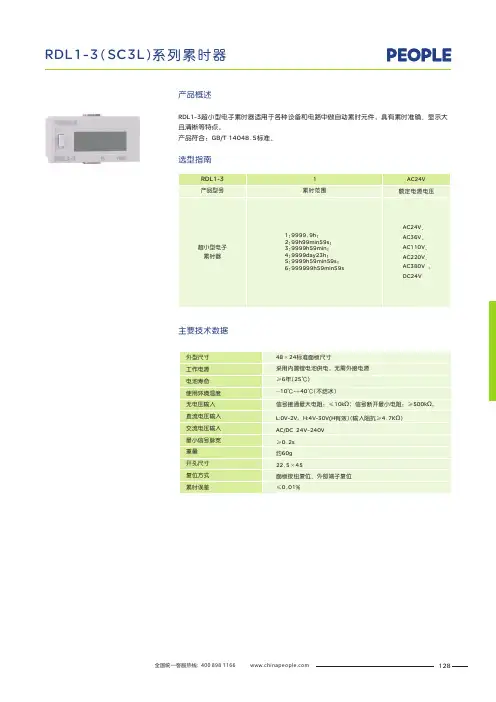
RDL1-3超小型电子累时器适用于各种设备和电路中做自动累时元件,具有累时准确、显示大且清晰等特点。
产品符合:GB/T 14048.5标准。
主要技术数据
产品概述
选型指南
128
接线方式
直流电压输入
交流电压输入
AC/DC
24240V
~2
与4已在内部接线
2与4已在内部接线
2与4已在内部接线
2与4已在内部接线
接开关
输入
复位
接开关
+
无电压输入
2与4已在内部接线
接开关
输入
复位
2与4已在内部接线
接开关
12
34
12
34
129
外形及安装尺寸
用户在订货时必须说明:
电子累时器的名称、型号及数量;
例如:RDL1-3-2A超小型电子累时器 数量50台
订货须知
安装面板适合厚度1~5mm
开孔尺寸:
复位按钮向下锁住
130。
JSY-3系列电压失压计时器使用说明书1用途JSY-3系列电压失压计时器(以下简称计时器)可用来监测电力计量用三相三线或三相四线电能表的运行状况,在线路失压(欠压)、有流时可自动按相记录其起始时间(年、月、日、时、分)、结束时间、相别、单次时间,并进行汇总。
计时器具有RS485通讯接口,可实现远程通讯。
计时器记录的数据,可用于供电部门的后台管理和分析,排除线路故障的辅助装置。
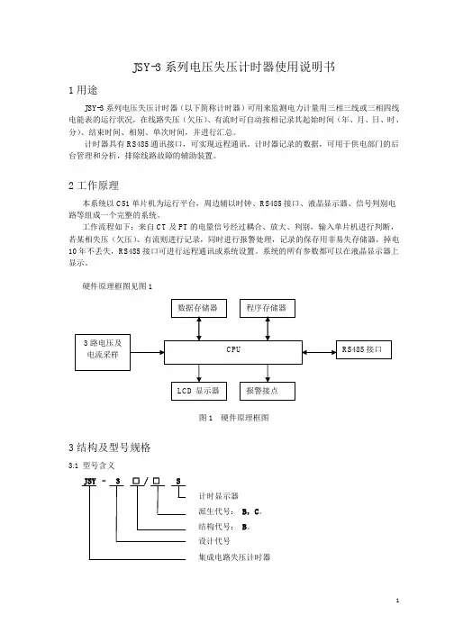
2工作原理本系统以C51单片机为运行平台,周边辅以时钟、RS485接口、液晶显示器、信号判别电路等组成一个完整的系统。
工作流程如下:来自CT及PT的电量信号经过耦合、放大、判别,输入单片机进行判断,若某相失压(欠压)、有流则进行记录,同时进行报警处理,记录的保存用非易失存储器,掉电10年不丢失,RS485接口可进行远程通讯或系统设置。
系统的所有参数都可以在液晶显示器上显示。
硬件原理框图见图1图1 硬件原理框图3结构及型号规格3.1 型号含义JSY – 3 □ / □ S计时显示器派生代号: B,C。
结构代号: B。
设计代号集成电路失压计时器3.2 结构代号图2 JSY-3B外形尺寸及安装开孔3.3 派生代号a)“B”电压回路Y形接线,电流回路有3个绕组且单独引出;b)“C”电压回路V形接线,电流回路Ia,Ic两个绕组且单独引出。
4技术数据4.1 参比电压:57.7V,100V。
4.2 额定电流:1A、5A。
4.3 参比频率:50Hz。
4.4 使用电压上限:120V。
4.5 正常工作电压下限:70V。
4.6 记时准确度:<2s/d。
4.7 掉电数据保存时间:>10年。
4.8 起动电压:参比电压的78%±2V。
4.9 返回电压:参比电压的85%±2V。
4.10 起动电流:额定电流的0.5%。
4.11 功率消耗:直流功率不大于7W,交流功率不大于1.5VA/Φ。
4.12 单条事件记录次数范围:950次。
4.13 汇总次数范围:3000条。

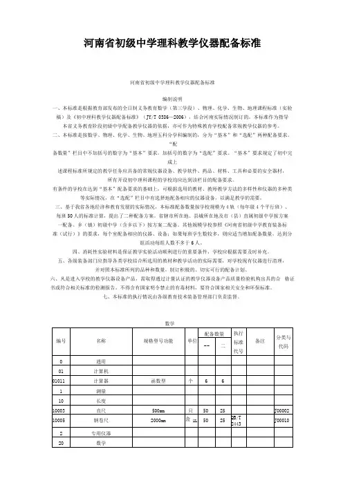
河南省初级中学理科教学仪器配备标准河南省初级中学理科教学仪器配备标准编制说明一、本标准是根据教育部发布的全日制义务教育数学(第三学段)、物理、化学、生物、地理课程标准(实验稿)及《初中理科教学仪器配备标准》(JY/T 0386—2006),结合河南实际情况制订的。
本标准作为指导本省义务教育阶段初级中学配备教学仪器的依据,亦可作为特殊教育学校配备常规教学仪器的参考。
二、本标准是按数学、物理、化学、生物、地理五科分学科编制的,分为“基本”和“选配”两种配备要求。
“配备数量”栏目中不加括号的数字为“基本”要求,加括号的数字为“选配”要求。
“基本”要求规定了初中完成上述课程标准所规定的教学任务应具备的常规仪器设备、教学软件、药品、材料、工具和必要的安全器材,所有开设初中理科课程的学校均应达到该栏目的配备要求。
有条件的学校在达到“基本”配备要求的基础上,可根据选用的教材、教师教学方法的多样性和仪器的多种类等实际情况,在“选配”栏目中有选择地配备相应的仪器设备,以满足教学的需要。
三、基于我省各地经济和教育发展的实际情况,本标准配备数量按学校规模为4轨(每年级4个平行班)、每班50人的标准计算,提出了二种配备方案。
省辖市所在地、县城所在地及市(县)直属初级中学按方案一配备。
乡(镇)初级中学(含乡以下)按方案二配备。
其他规模学校参照《河南省初级中学教育装备标准(试行)》的要求,每个室配备相应的仪器、设备;如果每班学生数较多,则应适当增加配备数量,达到分组活动每组人数不多于6人。
四、消耗性实验材料是保证教学实验活动顺利进行的重要条件,学校应根据需要及时补充。
五、各级装备部门应指导各类学校结合所选用的教材和教学活动的实际需要,对学校现有仪器进行清理,并对照本标准所列的品种和数量,制订积极的、切实可行的配备计划。
六、凡是进入学校的教学仪器设备产品,需取得通过计量认证的教学仪器设备产品质量检验机构出具的合格证书或符合相关标准的检测报告。
亚龙YL型维修电工实训考核装置亚龙YL型维修电工实训考核装置是一种用于电气工程和电气维修等领域的实训和考核设备。
该设备表面上看来是一个普通的电工工作台,但其内部设置有大量的电路、电器和电子元件,以满足学生和电工进行实际操作和维修的需要。
该设备的设计是为了学生和电工在实验室环境下模拟实际维修工作,以锻炼他们的技能和增强他们的实践操作经验。
不同于其他仅仅是展示或演示实验的电工设备,亚龙YL型维修电工实训考核装置具有实际的维修操作要求,并具有相当真实的实验效果。
该设备的主要性能参数包括:工作台尺寸860mm*650mm*1540mm;输送带宽度为120mm;输送带速度0.5-6m/s之间可调;工作环境温度为-10℃~40℃。
使用者可以根据需要不同的工作情况和需求设置电气参数,以符合不同的实验要求和维修环境。
亚龙YL型维修电工实训考核装置还具有以下特点:1、维修环境模拟真实。
设备内部设置了大量的电器和电子元件,使得学生在实验环境下可以完全模拟实际维修中的各种工作环境,更好地锻炼他们的实践操作能力;2、设备灵活性高。
该设备可以根据不同的实验和操作需求进行调整和设置,使其适应性更强,并可扩展功能以适应学生和专业人员的需要;3、维护简便。
该设备采用先进的电路和电子元件设计,使其有更强的稳定性和可靠性,维修操作简单轻松;4、支持多种应用场景。
该设备可以满足不同学科实验、技术培训、产品展示和客户维修需求等多种应用场景,具有非常广泛的应用前景。
总之,亚龙YL型维修电工实训考核装置是一种非常实用的电工维修设备,它为电工、学生、培训机构和企业等提供了一个与实际工作环境相似的模拟场景,使得学生和工人都能够在一个更真实的实践环境中锻炼和提升自己的技能和能力。


专利名称:电子输液报警器专利类型:实用新型专利发明人:李凭
申请号:CN01214739.7申请日:20010416
公开号:CN2487387Y
公开日:
20020424
专利内容由知识产权出版社提供
摘要:一种新型的电子输液报警器,利用蝶型管卡固定在输液器上。
当输液管内液面降过光敏电阻的瞬间,产生的光亮度变化,即达到报警,报警声是10秒钟优美的乐曲。
一旦报警20秒后还无护理人员到现场来处理,电子输液器会再次发声提醒。
本实用新型只有火柴盒大小,重量约25克,使用准确可靠,可设定距输液结束的报警时间,生产性好,制造成本低,适合批量生产。
申请人:李凭
地址:610091 四川省飞机工业公司41车间黄伟(转李凭)
国籍:CN
代理机构:成都中亚专利代理有限公司
代理人:陈亚石
更多信息请下载全文后查看。
高温高压滤失仪使用说明书版权所有2019青岛海通达专用仪器有限公司 青岛海通远达专用仪器有限公司部件号:17173修订版:19.1.0青岛海通达专用仪器有限公司青岛海通远达专用仪器有限公司本企业通过ISO9001质量管理体系认证、ISO14001环境管理体系认证和OHSAS18001职业健康安全管理体系认证。
本文档版权归青岛海通达专用仪器有限公司/青岛海通远达专用仪器有限公司所有。
未经书面许可,任何单位和个人不得将此文档中的任何部分公开、转载或以其他方式散发给第三方,否则,将追究其法律责任。
海通达® ®是青岛海通远达专用仪器有限公司的注册商标。
重要安全提示仪器使用前,请认真阅读以下安全指导,以保障人员和设备安全!◆要求仪器操作人员熟悉全部操作过程和操作时可能出现的意外情况,严格按说明书要求操作。
◆仪器使用前要检查各联接部位是否牢固。
◆严格按仪器技术要求配备电源、水源和气源。
◆仪器使用过程中要有人值守,一旦出现意外,必须迅速切断电源或水源、气源。
目录一、概述 (1)二、规格及型号 (1)三、技术参数 (1)四、仪器结构与工作原理 (1)五、操作说明 (4)六、维护与保养 (6)七、运输与储存 (7)八、故障判定与排除 (8)九、随机配件、工具一览表 (9)十、保修 (9)一、概述高温高压滤失仪是用于摸拟深井(高温高压)条件下钻井液和水泥浆的滤失量,同时可制取在高温高压状态下滤失后形成的滤饼。
二、规格及型号序号名称型号配置1 高温高压滤失仪GGS71-B 通孔/不通孔钻井液杯三、技术参数序号名称技术参数1 电源(220±11)V 50Hz2 功率1KW3 有效失水面积 3.5in2 (22.6 cm2)4 工作温度常温至232℃(±3℃)5 最大工作压力7.1MPa6 容量500mL7 气源氮气、二氧化碳气体(严禁使用氧气)四、仪器结构与工作原理(一)仪器结构1、仪器的结构组成1(图一)仪器结构图1)主体:由底座、立柱、加热系统等组成,是仪器的主体组件。
高温高压动态滤失仪简介高温高压动态滤失仪是一种用于研究油藏物性及开发采收工艺的实验装置,能够模拟高温高压下油藏的实际情况,监测研究不同条件下的油藏流体动态流失规律,为油藏工程研究提供可靠的数据和模拟实验手段。
工作原理高温高压动态滤失仪主要由工作槽、高温高压釜、过滤系统、压力控制系统等组成,其中釜中充入研究对象即油体或水体等,在不同的工作压力和温度下,通过控制釜中压力和采集流量数据,研究物质的渗透、反应等规律,最后通过过滤系统筛选收集数据,确保科学的数据准确性。
应用高温高压动态滤失仪广泛应用于油藏工程学、地质学等领域的研究中。
主要用于以下方面:1.模拟不同油藏温度和压力条件下物质滤失和渗透规律,验证油藏物性模型的精度。
2.研究不同采收工艺对油藏物质的影响,提高采收效率和经济效益。
3.对地下注水等一系列油藏开发工艺进行模拟实验,优化操作流程和提高开发效率。
4.研究油藏物质的性质和结构,为油藏资源的勘探和开发提供科学依据和技术支撑。
设备特点高温高压动态滤失仪具有以下特点:1.可模拟高温高压下油藏实际情况,确保模拟数据的可靠性和科学性。
2.独特的过滤系统设计,能够实现对数据的捕获和收集,保证研究数据的准确性。
3.高效的压力控制系统,能够对釜内压力进行精准控制,保证模拟实验数值的可靠性。
4.优质的材料和轻量化设计,保证设备运转稳定,操作方便,能够在高温高压的环境下长期运转并保持高质量输出。
总结高温高压动态滤失仪在石油勘探和开发的研究中具有非常重要的作用和价值,能够为油藏物性分析和采收工艺研究提供可靠的科学数据和实验手段,对于提高资源勘探和开发效率、降低石油开采成本有着积极作用。