优耐特UNTMMIB使用说明书
- 格式:docx
- 大小:66.35 KB
- 文档页数:35
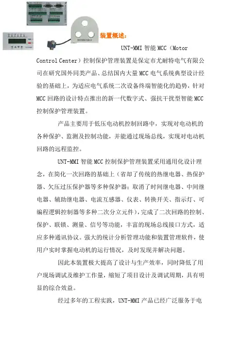
装置概述:UNT-MMI智能MCC(Motor Control Center)控制保护管理装置是保定市尤耐特电气有限公司在研究国外同类产品、总结国内大量MCC电气系统典型设计经验的基础上,为适应电气系统二次设备终端智能化的趋势,针对MCC回路的设计特点推出的新一代数字式、强抗干扰型智能MCC控制保护管理装置。
产品主要用于低压电动机控制回路中,实现对电动机的各种保护、监测及控制功能,并能通过现场总线,实现对电动机回路的远程监控。
UNT-MMI智能MCC控制保护管理装置采用通用化设计理念,在简化一次回路的基础上(省却了传统的热继电器、热保护器、欠压过压保护器等多种保护器;取消了时间继电器、中间继电器、辅助继电器、电流互感器、仪表、转换开关、指示灯、可编程逻辑控制器等多种二次分立元件),完成了二次回路的控制、保护、联锁、测量、信号等功能,丰富的现场总线接口方式,适应多种通讯协议。
强大的统计分析管理功能和装置管理软件,使用户实时掌握电动机的运行情况,及时发现并解决问题。
因此本装置极大提高了设计与生产效率,同时降低了用户现场调试及维护工作量,缩短了项目设计及调试周期,具有明显的综合效益。
经过多年的工程实践,UNT-MMI产品已经广泛服务于电力、化工、造纸、冶金、市政、煤炭、核工业等众多领域,运行稳定可靠。
装置特点:*采用32位工业级微处理器,速度快、精度高;*交流采样使用真有效值(RMS)算法,全面反映谐波电流的影响;*自适应变频采样技术,适用于变频器回路;*灵活的多种控制方式,各控制权限相互闭锁;*装置小型化设计,安装方式灵活;*全金属外壳设计,有效屏蔽外界电磁干扰;*汉字液晶,丰富的菜单显示,界面友好;*开关量输入回路采用强抗干扰设计,传输距离远,可靠性高;*装置内部控制触点带有保护电路,无需外加浪涌吸收器即可有效保护触点;*装置内带自记忆芯片,无需外配单独电源模块即可实现“抗晃电”功能及电压恢复自起动功能;*解决了热继电器和MCCB过载部分不能模拟MCC负荷的电特性和热特性的缺憾,在节省热继电器、简化MCCB构造的基础上,能更好地保护用电设备;*解决了MCCB瞬时脱扣器对长距离供电电动机端单相接地保护灵敏度不够的问题,省却了以往针对该问题单独加装单相接地保护的手段;*完善的过载保护。
【关键字】说明书目录致用户 (2)安全注意事项 (3)压缩机安装细节 (4)螺杆式压缩机概述及工作原理 (5)螺杆式压缩机结构 (7)主要功能件介绍 (9)操作说明 (15)压缩机气量控制、安全装置和电气原理 (21)维护与检查 (23)压缩机的毛病排除 (26)主要常用易损件表 (27)压缩机维护保养记录 (28)A/1尊敬的用户:首先,我们感谢您选购UNITED OSD公司的UD系列螺杆式空气压缩机。
本公司的产品在出厂之前均已经过严格的检验和测试,但为了确保机器安全、可靠、耐久地投入运行,请您务必在使用本机器之前详细阅读本说明书,充分掌握该螺杆压缩机组操作规范和技能,使其设备长期处于良好的工作状态。
本说明书中规定的条款适用于本公司的压缩机产品,附带的配套件说明书(如电动机、电器等),同样适用于该配套产品。
用户应了解当地的有关压缩机安装、使用方面的有关法律、法规,并予以遵守。
当本说明书中规定的条款与当地的有关法律、法规(特别是安全方面)不相同时,应按偏向于更安全的条款执行。
操作者有责任保证机器在安全的条件下运行,如果认为机器有不安全的隐患,应及时检修。
从您购买UNITED OSD公司的产品之日起,您将会得到UNITED OSD公司一流的售后服务,为了便于联络,我们提供本公司的地址、电话如下:工厂:邮编:商务部:邮编:电话:传真:E-mail:请妥善保存本说明书,以便随时查用。
UNITED SOD公司有权对产品进行修改或改进,但不负有对已出厂产品进行相应修改或改进的义务。
安全注意事项一、安装压缩机的安装应遵循当地的有关法律法规,并严袼遵守以下规定:1 、压缩机应采用承重能力大于机组重量的起重设备进行吊运,吊运速度、加速度应限制在许可的范围之内。
2 、尽量把压缩机安装在凉爽、干净、通风良好的地方,保证压缩机吸入的空气洁净及水分含量最小。
3 、压缩机吸入的空气不允许含有可燃气体及腐蚀性气体,以免可能引起爆炸或内部锈蚀。

优耐特U N T M M I B使用说明书修订版IBMT standardization office【IBMT5AB-IBMT08-IBMT2C-ZZT18】第1章概述UNT-MMI智能MCC控制保护管理装置是保定市尤耐特电气有限公司在研究国外同类产品、总结国内大量MCC电气系统典型设计经验的基础上,为适应电气系统二次设备终端智能化的趋势,针对MCC回路的设计特点推出的新一代数字式、强抗干扰型智能MCC控制保护管理装置。
产品可以实现对低压电动机的各种控制、保护和监测等功能,并能通过现场总线,实现对电动机回路的远程监控。
UNT-MMI智能MCC控制保护管理装置采用通用化设计理念,在简化一次回路的基础上(省却了传统的热继电器、热保护器、欠压过压保护器等多种保护器;取消了时间继电器、中间继电器、辅助继电器、电流互感器、仪表、转换开关、指示灯、可编程逻辑控制器等多种二次分离元件),完成了二次回路的控制、保护、联锁、测量、信号、通讯等功能,极大提高了设计与生产效率,同时降低了用户现场调试及维护工作量,缩短了项目设计及调试周期,具有明显的综合效益。
1.1 监测功能1)液晶显示电流、电压、功率、功率因数、热容量等2)4-20mA远传功能3)事故记录功能4)SOE记录功能1.2 保护功能1)过载保护2)堵转保护3)过流保护4)不平衡保护5)接地保护6)漏电保护7)低压保护8)过压保护9)相序保护10)缺相保护11)欠载保护12)tE保护13)起动过长保护14)超分断保护1.3 控制功能1)面板、固定输入、可编程输入和通讯四地控制方式可以灵活实现电机的就地/远方,自动/手动控制2)禁止起动功能防止频繁起停电机3)PLC连锁逻辑控制4)电压恢复自起动1.4 通讯功能1)通过RS485通讯接口,以MODBUS@RTU通讯协议实现系统组网2)通过Profibus-DP工业现场总线实现系统组网3)通过CAN现场总线进行通讯组网第2章结构及安装尺寸装置分为三部分:显示器、主机、电流互感器(CT)。

优耐燃气表使用说明摘要:1.优耐燃气表简介2.优耐燃气表使用方法3.优耐燃气表注意事项4.优耐燃气表的优点正文:一、优耐燃气表简介优耐燃气表是一款性能优良、安全可靠的燃气计量仪表,适用于城市煤气、天然气、液化气等多种可燃气体。
该燃气表采用IC 卡作为充值介质,具有操作简单、方便充值等特点,深受广大用户喜爱。
二、优耐燃气表使用方法1.将IC 卡插入控制器:按照燃气表具上的插卡指示标记(芯片面朝向),将IC 卡插入控制器。
2.当IC 卡插入控制器后,显示屏会显示“读卡”。
此时,控制器正在将IC 卡内的气量读入表内,进行充值。
当听到“嘀”声后,表示读卡完毕,阀门打开,液晶屏会轮流显示以下信息:- 读卡存入:最近一次读IC 卡充值的气量- 存量:存量原存量IC 卡读入量- 累计使用:表示该表从使用到目前的累计用量3.此时,可以拔出IC 卡,充值成功。
三、优耐燃气表注意事项1.在使用前,请检查各连接部位是否漏气,气源方向是否正确,严禁用明火试漏并在使用前排除管道内杂物。
2.请勿在使用过程中拆卸、改装燃气表,以免影响使用安全和性能。
3.当基表计量数据与IC 卡控制部分记录的数据出现不一致的情况时,请及时联系天然气公司进行处理。
4.燃气表使用过程中如出现问题,请立即关闭气源,并联系专业人士进行处理。
四、优耐燃气表的优点1.安全可靠:优耐燃气表采用先进的技术,具有良好的抗干扰性能,确保数据准确无误。
2.操作简单:IC 卡充值方式,方便快捷,无需担心充值卡丢失或损坏。
3.计量准确:优耐燃气表具有较高的精度,可精确计量燃气使用量。
4.环保节能:优耐燃气表采用低功耗设计,符合节能环保要求。
总之,优耐燃气表凭借其安全性、便捷性、准确性等优点,成为广大用户信赖的燃气计量仪表。

Your Ultima and Ultima Bath Transfers have been built to the highest standards of quality to ensure years of superior service. Please take the time to read this informative instruction guide and pay particular attention to the safety information provided.Here are some precautions you should take to reduce the risk of injury:1. Read and understand ALL instructions.2. To reduce the risk of injury or drowning, NEVER leave the userunsupervised or unattended while using this product.3. Determine, with a physician or therapist, the suitability of this productfor the intended user.4. Check regularly that all tubing, bolts, buckles, and other parts aretight at ALL times.5. When occupied, make sure the user is buckled in at all times.6. SAVE THESE INSTRUCTIONS.Thank you for choosing Inspired by Drive.Maximum Weight CapacityTo ensure the occupant’s safety, DO NOT exceed the following maximum weight limits:Option with Compact Transfer BaseUltima(with mesh seating)BTUC-8131M BTUS-8130M160 lb BTUC-8141L BTUS-8140L180 lbUltima Access (with cushion)BTUAC-5131M BTUAS-5130M160 lb BTUAC-5141L BTUAS-5140L180 lbOption with Foldable Transfer BaseUltima Bath(with mesh seating)BTUF-8130M BTUS-8130M160 lb BTUF-8140L BTUS-8130M180 lbUltima Access (with cushion)BTUAF-5130M BTUAS-5130M160 lb BTUAF-5140L BTUAS-5140L180 lbThe Ultima/Ultima Access Bath Transfer is shipped partiallyunassembled. Inside the package, you will find these following pieces:Adjustment Pull HandleRolling BaseBack & Calf FramesCover and Hardware KitBridgeTub BaseSeating ShuttleAnti-TippersAnti-TippersRolling Base Tub BaseSeating ShuttleCastersCastersLeg TubesLeg TubesAssembling the Back Support:1. One by one, pull on each of the pull tabs andchange the pivot angle to vertical (Fig. 1).Insert the U-shaped stainless steel back andcalf frames into the pivots and fasten withbolts and nuts provided.2. Insert the ends of the angle adjustment pullhandles into the small holes located on thepull tab on each side of the frame (Fig. 2).Firmly press the stainless steel capsover the ends of the pull handle. Pleaseensure that the end cap fits tightly overthe groove on the pull handle. Test it bytugging at the cap. If it comes off, thenreinstall.A.Back angle adjustment pull handle B.U-shaped back support frame C.Insertion point for back frame D.Back angle adjustment pull tab E. U-shaped calf support frame F. Calf angle adjustment pull handle (straight calf panel)G. Calf angle adjustment pull tab (bent calf panel)H. Knee support barF GD ABefore each use of your bath chair, please verify that the back and calf supports are properly installed and locked into position. When correctly installed, the pull tab should click into place and completely engaged into the slot. There should not be a gap between the pull tab and connector. See the figures below.Adjustments to the bath transfer SHOULD NOT be made while the product is in use or occupied.Cover Installation: (refer to seating diagram on pg. 4) Ultima (with mesh seating):• Pull on the angle adjustment pull handles (A, G) to set the backrest and calf supports to the mostupright position (Fig. 3). Slip the cover over thebackrest and adjustment pull handle and then calf support and pull handle (Fig. 4). Wrap the hook & loop straps around the top side-tube and secureunderneath the seating (Fig. 5).Ultima Access (with cushion):• Pull on the back angle adjustment pull handle (A) to set the backrest support to the most uprightposition (Fig. 1). Slip cover over the back rest and adjustment pull handle (Fig. 4). Wrap the hook& loop straps around the seat frame and secureunderneath the seating (Fig. 6).Adjusting Back Angle:1. Locate the adjustment pull handle (A) on the backof the seating under the cover (it is not necessary to remove the cover to operate the lever). Usingboth hands, grip the lever and back frameand squeeze together.2. With a lifting motion, adjust the back angleup or down.WARNING: Back angle should not beadjusted when the seating is occupied. Adjusting Calf Support Angle:1. On the calf support frame, under the cover, locatethe adjustment pull handle (G) for the Ultima orthe adjustment pull tab (Fig. 1) on each leg forthe Ultima Access It is not necessary to removethe cover. Using both hands, grip the lever andcalf support frame and squeeze together for theUltima or pull out the pull tabs for Ultima Access.2.With a lifting motion, adjust the angle up or down.Figure 3Figure 4Figure 5 Hook & loop strapThe rolling base has commode pail systemthat is pre-installed to the system. If you needto remove it, please follow these steps:1. Turn the rolling base upside-down.2. Remove both support rails by using aPhillips screw driver (Fig. 7).Rolling Base Assembly:1. Slide the anti-tipper clamp over the rearleg tube making sure that the notched endfaces upward (Fig. 8).2. Loosely tighten the clamp and install theanti-tipper tube from the bottom, makingsure that there is about ¼” to ½” clearancefrom the floor. Tighten the clamp.3. If ordering footrest option, slide thefootrest clamp over the front leg tub. Alignthe center slot on the clamp to the holeson rolling base leg (Fig. 8). Secure theclamp with bolt. The height is adjustableand can be re-positioned when the seatingis fully assembled for correct fit.4. Insert the caster into the socket on thebottom of the individual leg tube (Fig. 9).5. Insert the leg tube into the rolling base bydepressing the locking button and slidingthe leg tube up the frame (Fig. 10).Tub Base Assembly:6. Insert the individual leg tube into the tub base bydepressing the locking button and sliding the legtube up the frame (Fig. 10).Figure 9Figure 7Figure 10Seating and Rolling Base Assembly:1. Insert the guide rail hooks into the guide rails and slide the seatingframe assembly onto the rolling base (Fig. 11). Be sure to slide the seating all the way until the safety locking latch clicks into position on the base (Fig. 12).Note: If you need to change the way the seating faces, you mayremove the rolling base, rotate it 180° and insert the guide rail hooks into the guide rails, and slide the seating frame assembly back onto the rolling base.2. If ordering with footrest option, insertthe footrests onto the footrest clamps byaligning the buttons on footrests with thenotches on the clamp (Fig 13).Figure 121. Set the desired height on both tub base and rolling base bydepressing the locking button on leg tubes and slide them up or down.2. Place the tub base inside the tub orshower (Fig. 14). Level the frame byadjusting the leveling feet making sure thatthe height of the rolling base is the sameas the tub base (Fig. 15). Lock the levelingfeet in place with the jam nuts.3. Place the bridge in position to connect thetub base to the rolling base (Fig. 16). Besure that the bridge sits in the indent slotsso that it is flat with the top of the rails. Ifthe bridge does not sit flat, check the height adjustment on both bases. The heightmust be the same on both bases for proper bridge fit and smooth transfers.WARNING: Never operate the transfersystem if the bridge is not seatedsecurely in place and flat with therolling and transfer base rails.4. To transfer the seating frame, lift up on thesafety latch located behind the seat, slidethe seat to the desired position (Fig. 17).The seat is in position when the safety latch locks on the other side of the transfer base.5. The bridge can be removed during use sothe shower door or curtain can be closed.WARNING: Do not remove the bridgeunless the safety lock is latched.Figure 14Figure 16Figure 17Rolling Base Assembly: 1.Slide the anti-tipper clamp over the rear leg tubemaking sure that the notched end faces upward(Fig. 18).2. Loosely tighten the clamp and install the anti-tipper tube from the bottom, making sure thatthere is about ¼” to ½” clearance from the floor.Tighten the clamp.3. If ordering footrests, slide the footrest clamp overthe leg tubes making sure the notched end facesupward. Align the center slot on the clamp to theholes on rolling base leg (Fig 18). Secure theclamps with bolts. The height is adjustable andcan be re-positioned when the seating is fullyassembled for correct fit.4. Insert the casters into the socket on the bottom ofthe individual leg tubes (Fig 19).5. Insert the leg tubes into the rolling base bydepressing the locking buttons and sliding the legtube up the frame.Seating and Rolling Base (Shuttle) Assembly:6. Insert the guide rail hooks into the guide rail and slide the seating frameassembly onto the rolling base. (Fig. 20). Be sure to slide the seating all the way until the safety latch locks into position on the base (Fig. 21).N ote: To remove the seating from base, release the safety latch in the back and press the Slider Safe™ button (Fig. 22).Figure 21Figure 22 Figure 20Guide RailGuide Rail HooksFigure 19Align slot tothe holesNotchFigure 187. If ordering with footrests, insert them byaligning the slots on the footrests with thenotches onto the footrest clamps (Fig. 23).Tub Base Assembly:8. Unfold the tub base legs by pulling thelegs out and rotating them into position.Each leg is in position when it locks intothe slots at the bottom of the frame rail(Fig. 24).Note: When unfolding the legs, grab the leg on the darker-colored pivot section as close to the top as possible. This will prevent damage to the leg and make it easier to unfold.Note: When folding the tub base for storage, fold the two front legs (the legs closest to the latch) first. The adjusting legs do not have to be removed when folding for storage.SlotFine-tuning knobSlot1. With the legs in the open and lockedpositions, place the transfer base intothe shower or tub (Fig 25). Then, roll theseating to the end of the tub base (Fig 26).Note: The shuttle base is reversible andcan be installed on the slide rails in eitherdirection to accommodate any bathroomlayout.2. Adjust the leg height of the tub base sothe frame tubes are at the same height asthe rolling base and both are aligned when positioned end to end (Fig. 27).3. Make rough adjustments (¾”) with thedetent buttons (Fig. 27), or make fineadjustments by loosening the back knobs(refer back to Fig. 24) and turning the legs to the desired height. Tighten the adjusting knobs when the height is set.4. When the heights of the tub base and theas close as possible to the tub base. Place the tongue of the manual locking latch over the receiver on the tub base (Fig. 28).5. Lock the rolling base to the tub basewith the center latch before attemptingto transfer or slide the rolling base. Loopthe tongue from the tub base over thehook receiver on the rolling base. Lockthe base to the seating by pulling down onthe manual locking handle until the safetylock clicks in place (Fig. 29). The safetylock prevents the seating base from rolling away.Figure 25Figure 26Figure 28Figure 29 detent buttonfine-tuningknob6. Prior to transfer, raise the calf support high enough to clear the sidesof the tub (Fig. 30).7. When transferring, roll the shuttle baseuntil the latch on the back clicks into theposition lock bolt (Fig. 31). There areposition lock bolts on rolling base andtub base. These will lock the seating intoa secure position and eliminate any sidemovement and/or rolling during use.Note: The lock bolt on the tub base can berepositioned into two other locationsfor better positioning of the individualover the tub in certain applications(Fig. 32).8. To release the lock, pull upward onthe black knob on the lower backof the slider and allow it to travelbetween the coupled rolling base and bath tub base.Figure 31Figure 30Soapy water or mild cleansers may be used on all parts of your Ultima and Ultima Access Bath Transfers. Harsh abrasive cleansers may dull the finish.The fabric cover for the bath transfer is made of polyester that is durable, antimicrobial, resilient, quick drying, fade resistant, and machine washable.Cleaning Instructions:1. Remove the seating cover by following these steps below:• Adjust the back and calf support frames to horizontal. Turn theseating up-side down and remove hook & loop strap.• Slip the cover over the back and calf supports.2. Using warm water (100°F/38°C) and household laundry detergent,wash the cover in the washing machine using gentle cycle.3. Air dry.To order accessories for the bath transfer system please call Customer Service at (800) 454-6612 or email ************************.Head Support PadDesigned for better head positioningLateral Support PadDesigned for better torso positioning Positioning BeltQuick release strap forvarious loops on chairallowing for multiplepositions. Two belts areincluded.Detachable Armrest Offer four height positionsAdjustmentBracketRaise front seat height to2.5”, 3” or3.5”Padded AbductorAttaches easily to improve hipalignment and stabilize seating positionFootrestsFoot SupportPelvic Positioning BeltInspired by Drive warrants this product to be free of defects in material and workmanship. Our obligation under this warranty is limited to repair or replacement of any part or entire unit at our option for a period of one year from date of delivery to the original purchaser. The warranty does not include cost of inconvenience, property damage, misuse, abuse, crash or similar incidents. The warranty will notapply if product has been tampered with or repaired by unauthorized individuals.。
UNT-HVSS中高压固态软起动柜使用说明书(V3.0)●操作本设备之前,请仔细阅读使用说明书。
●对设备的任何电气或机械部件进行操作之前,必须断开UNT-HVSS 系列中高压固态软起动柜的控制电源和动力电源。
●安装及维护操作,应严格按照本手册及相关国家标准及行业惯例,否则因没有按照相应指导规范操作所引起的一切不良后果制造商概不负责。
●在运行过程中可以通过停止按键或急停按键使电动机停机,但此时软起动柜仍带电。
●文中介绍的产品和设备可能会因技术原因随时变更或修改。
我们保留更改的权力。
注意事项:该设备只能用在产品目录和技术说明中所规定的使用情况下。
正确地进行运输、仓储、安装和装配以及谨慎操作和维护,是产品无故障可靠运行的前提条件目录前言 (1)第一章概述 (1)1.1 概述 (1)1.2 技术指标和性能 (1)1.3 主要功能单元 (3)1.4 工作原理 (4)1.5 保护功能 (5)1.6 控制系统 (6)第二章安装 (8)2.1 接收和开箱 (8)2.2 初始检查 (9)2.3 使用环境 (9)2.4 柜体进线、出线位置示意图 (9)2.5 常用软起动柜数据说明 (11)2.6 安装 (11)2.7 设备附加改造 (12)2.8 通电前准备 (12)2.9 警告 (12)2.10 接地 (12)第三章起动 (13)3.1 起动的准备步骤: (13)3.2 介绍 (13)3.3 加速调整 (13)3.4 减速调整(水泵控制) (14)3.5正常操作顺序 (16)第四章操作与设置 (17)4.1 初次上电调试 (17)4.2 设置参数 (17)4.3 保护参数 (19)4.3 故障查询 (21)4.4 高级操作 (21)4.5 负责人界面 (23)第五章维护及故障排除 (24)5.1 故障分析 (24)5.2 UNT-HVSS基本原理图 (26)5.3 日常维护 (26)第六章初始整定值表 (26)前言感谢您使用保定市尤耐特电气有限责任公司生产的UNT-HVSS系列中高压固态软起动柜。

目录致用户 (2)安全注意事项 (3)压缩机安装细节 (4)螺杆式压缩机概述及工作原理 (5)螺杆式压缩机结构 (7)主要功能件介绍 (9)操作说明 (15)压缩机气量控制、安全装置和电气原理 (21)维护与检查 (23)压缩机的故障排除 (26)主要常用易损件表 (27)压缩机维护保养记录 (28)A/1尊敬的用户:首先,我们感谢您选购UNITED OSD公司的UD系列螺杆式空气压缩机。
本公司的产品在出厂之前均已经过严格的检验和测试,但为了确保机器安全、可靠、耐久地投入运行,请您务必在使用本机器之前详细阅读本说明书,充分掌握该螺杆压缩机组操作规范和技能,使其设备长期处于良好的工作状态。
本说明书中规定的条款适用于本公司的压缩机产品,附带的配套件说明书(如电动机、电器等),同样适用于该配套产品。
用户应了解当地的有关压缩机安装、使用方面的有关法律、法规,并予以遵守。
当本说明书中规定的条款与当地的有关法律、法规(特别是安全方面)不相同时,应按偏向于更安全的条款执行。
操作者有责任保证机器在安全的条件下运行,如果认为机器有不安全的隐患,应及时检修。
从您购买UNITED OSD公司的产品之日起,您将会得到UNITED OSD公司一流的售后服务,为了便于联络,我们提供本公司的地址、电话如下:工厂:邮编:商务部:邮编:电话:传真:E-mail:请妥善保存本说明书,以便随时查用。
UNITED SOD公司有权对产品进行修改或改进,但不负有对已出厂产品进行相应修改或改进的义务。
安全注意事项一、安装压缩机的安装应遵循当地的有关法律法规,并严袼遵守以下规定:1 、压缩机应采用承重能力大于机组重量的起重设备进行吊运,吊运速度、加速度应限制在许可的范围之内。
2 、尽量把压缩机安装在凉爽、干净、通风良好的地方,保证压缩机吸入的空气洁净及水分含量最小。
3 、压缩机吸入的空气不允许含有可燃气体及腐蚀性气体,以免可能引起爆炸或内部锈蚀。

P/N:110401108881X1. OverviewThe UT203+/UT204+ are portable true RMS AC/DC clamp meterswith automatic range. They are designed according to EN61010-1CAT II 600V/CAT III 300V safety standards, and come with full-functionprotection which ensures users a safe and reliable measurementexperience. Aside from basic measurement functions, they also havehigh precision current scale and high voltage frequency measurementextension. UT204+ also comes with live/neutral wire detection. Thesemeters are great tools for electrical measurements up to 1000A current.UT203+/UT204+AC/DC Clamp MetersUser ManualPrefaceThank you for purchasing the new clamp meter. In order to use thisproduct safely and correctly, please read this manual thoroughly,especially the Safety Instruction part.After reading this manual, it is recommended to keep the manual atan easily accessible place, preferably close to the device, for futurereference.Limited warranty and liabilityUni-Trend guarantees that the product is free from any defect in materialand workmanship within one year from the purchase date. This warrantydoes not apply to damages caused by accident, negligence, misuse,modification, contamination and improper handling. The dealer shallnot be entitled to give any other warranty on behalf of Uni-Trend. Ifyou need warranty service within the warranty period, please contactyour seller directly.Uni-Trend will not be responsible for any special, indirect, incidentalor subsequent damage or loss caused by using this device. A s somecountries or regions do not allow limitations on implied warranties andincidental or subsequent damages, the above limitation of liability maynot apply to you.2. FeaturesTrue RMS measurementAudio visual NCV electric field detectionHigh voltage frequency range: 10Hz~60kHz; low voltage frequencyrange: 60Hz~10MHzUT203+ AC/DC current range: 40A, 400A, frequency response:45Hz~400HzUT204+ AC/DC current range: 60A, 600A, frequency response:45Hz~400Hz, live/neutral wire detectionACA/DCA mode memory function for current measurementLarge capacitance (UT203+: 40mF, UT204+: 60mF) and temperatureTmeasurement (U204+)Large LCD and fast refresh rate (3 times/s), capacitance measurementresponse time:≤1mF: less than 3s; ≤10mF: about 6s; ≤60mF: about 8sFull-function false detecting protection for up to 600V (3.6kVA)energy surge; overvoltage and overcurrent alarmThe power consumption without backlight is about 1.8 mA. Thecircuit has an automatic power saving function. The consumptionin sleep state is <11uA, which effectively extends the battery life to400 hours.Please read the safety and warning parts in this manualthoroughly.Caution: Please read the safety instructions carefully before use.3. Standard AccessoriesOpen the package and check the below items, if any is missing ordamaged, please contact your supplier immediately:User manual ----------------------- 1 pcTest leads --------------------------- 1 pairK-type temperature probe ------ 1 pc (Only UT204+)Cloth bag ---------------------------- 1 pc4. Safety InstructionsThe meter is designed according to EN61010-1, 61010-2-032/033and electromagnetic radiation protection EN61326-1 safety standards,and conforms to double insulation, CAT II 600V, CAT III 300V andpollution grade II. In case the meter is not used properly as instructions,the protection provided may be weakened or lost.Do not use the tester or test leads if they appear to be damaged.Do not use the meter if the rear or battery cover is open.Keep fingers behind finger guard and do not touch the live parts toprevent electric shock.The function switch should be correctly set before measurement.It is forbidden to switch scale during measurement or damage mayoccur!Do not apply AC/DC voltage over 600V to any terminal to preventelectric shock or damage.Use caution to avoid shock hazard when working with voltagesabove DC 60V, or AC 30Vrms.Never input voltage or current which exceeds the specified limit.Maximum range should be selected if measured value is unknown.Before measuring resistance, diode and continuity, please disconnectall power and fully discharge all capacitors to avoid inaccuracy.When the “ ” symbol appears on the LCD, please replace thebatteries in time to ensure measurement accuracy. Batteries shouldbe removed If the meter is long-term idle.Do not change the internal circuit of the meter to avoid damage tothe meter and user!Do not expose the meter in high temperature/humidity, flammable,explosive or intense magnetic environments.Clean the meter casing with a soft cloth and mild detergent.Do not use abrasives or solvents!6. General SpecificationsMax LCD display counts: 4099 (U203+), 6099 (U204+)T TPolarity display: AutoOverload display: “OL” or “- OL”Low battery indication: “ ” means low batteryLow battery shutdown prompt: The “Lo.bt” interface appears on LCDand lasts for about 10s, the buzzer beeps 3 times, and the meterautomatically shuts down.Test position error: If the source under test is not placed at the centerof the clamp jaws when measuring current, ±1.0% additional error inreading may be produced.Drop protection: 1mThe maximum size of jaw opening: 28mm in diameterBattery: AAA 1.5V battery × 2Auto power off (adjustable): The meter will auto power off if there is nooperation for 15 min.Dimensions: 215mm × 63.5mm × 36mmWeight: About 235g (including batteries)Altitude: 2000mOperating temperature and humidity: 0°C~30°C (≤80%RH), 30°C~40°C(≤75%RH), 40°C~50°C (≤45%RH)Storage temperature and humidity: -20°C~+60°C (≤80%RH)Electromagnetic compatibility: RF=1V/m, overall accuracy=specifiedaccuracy+5% of range; RF>1V/m, no specified calculation1) NCV sensing end2) Clamp jaws3) Hand guard4) LED indicator5) Jaw opening trigger6) Function scale knob7) LCD display8) Function buttons9) Signal input jack (red and positive +)10)COM input jack (black and negative -)8. Button DescriptionSELECT ButtonIn composite scale, press this button to switch between the correspondingfunctions or ranges;HOLD/BACKLIGHT ButtonShort press this button to enter/exit the data hold mode, and long press(about 2s) this button to turn on/off the backlight.MAX/MIN Button(valid for ACV/DCV, ACA/DCA, “C/”F, resistance and capacitance scales)Short press this button to enter the maximum/minimum measurement modeand long press this button to exit.REL Button(valid for ACV/DCV, DCA, “C/”F and capacitance scales).Press this button to store the current reading as a reference for futurereadings. When the LCD display value is reset to zero, the stored readingwill be subtracted from the future readings. Press this button again to exitthe relative value mode.9.Operating Instructions9.1 AC/DC Current Measurement (Picture 2)Select the corresponding current range.Press the trigger to open the clamp jaws, and fully enclose one conductor.Only one conductor can be measured at a time, or the measurementreading will be wrong.Caution:Do not insert the testing leads during current measurement to avoidelectric shock.The current measurement must be taken with safeguard protection.Press the REL button to return to zero before the DC current measurement,and meanwhile the center hole of jaw should be perpendicular to thecurrent direction to ensure accuracy.The open circuit zeroing reading may be relatively large after (high) DCcurrent measurement. Please perform the A C current detection again tocounteract the remanence signal by alternating electric field.9.2 AC/DC Voltage and Voltage Frequency (% duty cycle)Measurement (Picture 3)Select the corresponding function scale.Insert the red test lead into the “positive” jack, and the black intothe “COM” jack.Connect test leads with both ends of the measured objects.Caution:Do not input voltage above 600V to prevent electric shock or damage.The input impedance of each range scale is 10MΩ, this load effectin high resistance measurement may cause error. If the inputimpedance is lower than 10kΩ, the error can be ignored (≤0.1%).Be cautious to avoid electric shock when measuring high voltage.Please check the functions by applying a known voltage before use.9.3 Continuity Test/Resistance/Diode/CapacitanceMeasurement (Picture 4)Select the corresponding function scale.Insert the red test lead into the “ ” jack, and the blackinto the “COM” jack.Connect test leads with both ends of the measured object.Caution:Do not input voltage above DC 60V or AC 30V to avoid personalinjury.Please disconnect all the other parts of the circuit to avoid inaccuracy.Before the resistance online measurement, please do disconnectall the power and fully discharge all capacitors to avoid injury ordevice damage.If the resistance is over 0.5Ω when the test leads are short-circuited,please check the test leads for looseness or other abnormalities.If the measured resistor is open or the resistance exceeds themaximum range, the LCD will display “OL”.Measured value = displayed value – probe short circuit valueIt is recommended to use “REL” measurement mode for capacitanceless than 100nF.9.4 Temperature Measurement (UT202+ only, Picture 5)Select the temperature measurement function scale.Insert K-type thermocouple to the meter, fix the temperature probeon the measured object, and read after the value is stable.5. SymbolsPicture 4Picture 5UT204+UT203+40.00A 400.0A 60.00A600.0A0.01 A0.1 A±(2%+5) UT204+UT203+40.00A 400.0A 60.00A600.0A0.01 A0.1 A±(2%+5)UT204+UT203+400.0mV4.000V40.00V400.0V600V600.0mV6.000V60.00V600.0V0.1mV0.001V0.01V0.1V1V±(.+07%3)±(.+05%2)UT204+UT203+4.000V40.00V400.0V600V6.000V60.00V600.0V0.001V0.01V0.1V1V0.01Hz~0.01kHz±(.+10%5)±(.+08%5)±(.%+)052Voltage Frequency10Hz60KHz~1.Ω0001V.400.0Ω/600.0Ω4.000V/6.000VUT204+UT203+400.0Ω4.000kΩ40.00kΩ400.0kΩ4.000MΩ40.00MΩ600.0Ω6.000kΩ60.00kΩ600.0kΩ6.000MΩ60.00MΩ01.Ω0001K.Ω001K.Ω01K.Ω0001M.Ω001M.Ω±(.+10%2)±(.+08%2)±(.%+)255UT204+UT203+40.00nF400.0nF4.000uF40.00uF400.0uF4.000mF40.00mF60.00nF600.0nF6.000uF60.00uF600.0uF6.000mF60.00mF0.01nF0.1nF0.001μF0.01μF0.1μF0.001mF0.01mF±(%+)45±%1010Hz~10MHz0.01Hz~0.01MHz±(0.1%+4)0.1%~99%0.1%±(3%+5)10.9NCVNCVEFLoEFHI-40℃~40℃40℃~500℃500℃~1000℃-40℉~104℉104℉~932℉932℉~1832℉±4℃±(1.5%+5)±(2.0%+5)±6℉±(2.0%+6)±(2.5%+4)1℃1℉9.5 NCV AC Electric Field Sensing and Live/Neutral Wire Measurement (Picture 6a)9.5.1 AC Electric Field SensingThe electric field sensing sensitivity is divided into two levels (“EFHI” and “EFLo”). The meter defaults to “EFHI”. Users can select different sensitivity levels according to the intensity of the measured electric field. Select "EFHI" of NCV when electric field is around 220V AC 50Hz/60Hz. Bring the NCV sensing end close to a charged electric field (socket, insulated wire, etc.). The LCD will display the segment "-" with beeps and red LED flashing. A s the intensity of the measured electric field increases, the more segments (----) display, the higher frequency of buzzer beeps and LED flashes. Select “EFLo” when the electric field is around 110V AC 50Hz/60Hz.Caution:Use the NCV sensing end to approach measured electric field, otherwise the measurement sensitivity will be affected. When the measured electric field voltage is over 100V A C, observe whether the conductor is insulated to avoid personal injury.9.5.2 Live/Neutral Wire Measurement (only UT204+) (Picture 6b)a. Select the LIVE function scale.b. Insert the red test lead into the “ ” jack, make the blacksuspended, and use the red test lead to touch the socket test leadto distinguish the live/neutral wire.or bare wirec. When the neutral wire or uncharged object is detected, the "----" is displayed.d. When the >60V AC "live wire" is detected, the LCD will displayaccompanied by audio/visual indication."LIVE"Caution:When using this function, in order to avoid the COM input interference, which will affect the electric field and the accuracy, please pull the black test lead out of the COM input.Do keep your hand away from the meter casing. The accuracy may be unstable under the dense high-voltage. In this case, it should be judged by LCD and sound frequency together.9.6 OthersAuto power off: The meter will automatically power off to save power if there is no operation for 15 min. You can wake it up by pressing any button or restart it after turning the switch to OFF.Press and hold the SELECT button in off state and then turn on the meter again to disable the auto power off function. Restart the meter after shut it down to resume this function.Buzzer: When any button is pressed or the function switch is turned, if it is valid, the buzzer will make one beep (about 0.25s). The buzzer will also beep intermittently to indicate the over range during the voltage or current measurement.Low battery detection: The battery voltage will be automatically detected as long as the meter is on. If it is lower than 2.6V, the LCD will display the “ ” symbol.Low battery shutdown function: When the battery voltage is lower than 2.5V, the LCD displays the “ ” symbol, the “Lo.bt” interface appears and lasts for about 10s, the buzzer makes consecutive beeps 3 times, and then the meter automatically shuts down (no is displayed).interface10. Technical SpecificationsAccuracy: ± (%reading + counts), the calibration period is 1 year. Ambient temperature and humidity: 23°C±5°C; ≤80%RH. Temperature coefficient: the accuracy assured temperature condition is 18°C-28°C, the range of ambient temperature fluctuation is stable within ±1°C. When the temperature is less than 18°C or over 28°C, the additional temperature coefficient error is 0.1 x (specified accuracy)/°C.10.1 Current MeasurementAC CurrentRangeResolution AccuracyDC CurrentCaution:Accuracy guarantee range: 5%~100% of rangeWhen the measured current reaches the warning value, therewill be an alarm sound (UT203+: 410A, UT204+: 610A) With DC current DCA mode, LCD may display non-zero value in open circuit state, users can press "REL" button to clear display to zero before each measurement. 10.2 Voltage MeasurementDC VoltageRangeResolution AccuracyAC Voltage/Voltage FrequencyRangeResolution AccuracyCaution:UT203+: short press "SELECT” in AC voltage/Hz scale to enter the Hzfunction;UT204+: long press "SELECT" to enter/exit the Hz function, the inputrange over 5V.The input impedance is about 10MΩCurrent/voltage frequency response: 45Hz ~ 400Hz, displays true RMSvalueAccuracy guarantee range: 1%~100%AC crest factor of non-sinusoidal wave can reach 3.0 at 4000 countswhile can only reach 1.8 at 6000 counts, the additional error should beadded for the corresponding crest factor as follows:A. Add 3% when the peak factor is 1 ~ 2B. Add 5% when the peak factor is 2 ~ 2.5C. Add 7% when the peak factor is 2.5 ~ 310.3 Continuity/Diode MeasurementFunction Range Resolution Accuracy≤10Ω: Consecutive beeps≥31Ω: No beepThe median: uncertainThe open circuit voltage isabout 4VFor the silicon PN junctiondiode, the voltage value isgenerally about 0.5~0.8V.10.4 Resistance MeasurementRangeResolution AccuracyCaution:Measured resistance value = displayed value – resistance valueof short circuited test leadsOpen circuit voltage is about 1VOverload protection: 600Vrms10.5 Capacitance MeasurementRangeResolution AccuracyCaution:Measured value = displayed value - open circuit value of the test leads(For capacitance ≤100nF, “REL” mode is recommended, open circuithas residual reading). The guaranteed accuracy is 1%~100%.Overload protection: 600Vrms10.6 Frequency MeasurementRangeRangeResolutionResolutionAccuracyAccuracy10.7 Duty Ratio MeasurementCaution:Measurement sensitivity:≤100kHz: 200mVrms≤ input range≤30Vrms;>100kHz~1MHz: 600mVrms≤ input range≤30Vrms;>1MHz~10MHz: 1Vrms≤ input range≤30Vrms.Duty ratio is only applicable to ≤10kHz square wave measurementwith a range of 1Vp-p:If frequency≤1kHz, duty cycle will be 10.0%-95.0%;If frequency>1kHz, duty cycle will be 30.0%-70.0%.10.8 Temperature Measurement (UT204+ only)Range Resolution AccuracyCaution:The meter displays "OL" after startup, it is only suitable for K-typethermocouple (Nickel-Chromium ~ Nickel-Silicon temperaturesensor) and temperature measurements below 1000°C/1832°F.The formula for Celsius to Fahrenheit is °F =1.8°C + 32.RangeElectric fieldsensingsensitivity levelAccuracyThe electric field sensing sensitivityis divided into two levels (“EFHI” &“EFLo”). The meter defaults to “EFHI”.a) AC voltage above 24V±6V can besensed. "EFLo" mode is recommendedwhen the power frequency voltage is110V.b) "EFHI" can be set in 220V condition.AC voltage above 74V±12V can besensed with getting close to wires,and identify whether the main socketis charged or to judge the live/neutralwire of socket according to the intensityof sensing.Note: Test results may be affected bydifferent socket designs or wire Insulation thickness.10.10 LIVE Function (UT204+ only)11. MaintenanceWarning: Before opening the rear cover of meter, remove testleads to avoid electric shock.11.1 General MaintenanceClean the meter casing with a soft cloth and mild detergent. Donot use abrasives or solvents!Do not use the tester or test leads if they appear to have anyabnormality.The maintenance and service must be implemented by qualifiedprofessionals or designated departments.11.2 Battery Replacement (Picture 7)When the “ ” symbol appears on the LCD, please replace thebatteries in time to ensure measurement accuracy. Batteriesspecification:2 standard AAA 1.5V batteries.OperationTurn off the meter and remove the test leads from the input terminals.Unscrew the screw of the battery compartment, remove the batterycover, and take out the used batteries as shown.Replace the 2 standard AAA batteries according to the polarityindication.RangeResolution AccuracyPicture 7。
第1章概述UNT-MMI智能MCC控制保护管理装置是保定市尤耐特电气有限公司在研究国外同类产品、总结国内大量MCC电气系统典型设计经验的基础上,为适应电气系统二次设备终端智能化的趋势,针对MCC回路的设计特点推出的新一代数字式、强抗干扰型智能MCC控制保护管理装置。
产品可以实现对低压电动机的各种控制、保护和监测等功能,并能通过现场总线,实现对电动机回路的远程监控。
UNT-MMI智能MCC控制保护管理装置采用通用化设计理念,在简化一次回路的基础上(省却了传统的热继电器、热保护器、欠压过压保护器等多种保护器;取消了时间继电器、中间继电器、辅助继电器、电流互感器、仪表、转换开关、指示灯、可编程逻辑控制器等多种二次分离元件),完成了二次回路的控制、保护、联锁、测量、信号、通讯等功能,极大提高了设计与生产效率,同时降低了用户现场调试及维护工作量,缩短了项目设计及调试周期,具有明显的综合效益。
1.1 监测功能1)液晶显示电流、电压、功率、功率因数、热容量等2)4-20mA远传功能3)事故记录功能4)SOE记录功能1.2 保护功能1)过载保护2)堵转保护3)过流保护4)不平衡保护5)接地保护6)漏电保护7)低压保护8)过压保护9)相序保护10)缺相保护11)欠载保护12)tE保护13)起动过长保护14)超分断保护1.3 控制功能1)面板、固定输入、可编程输入和通讯四地控制方式可以灵活实现电机的就地/远方,自动/手动控制2)禁止起动功能防止频繁起停电机3)PLC连锁逻辑控制4)电压恢复自起动1.4 通讯功能1)通过RS485通讯接口,以MODBUS@RTU通讯协议实现系统组网2)通过Profibus-DP工业现场总线实现系统组网3)通过CAN现场总线进行通讯组网第2章结构及安装尺寸装置分为三部分:显示器、主机、电流互感器(CT)。
2.1 显示器面板面板尺寸为103×60指示灯功能颜色通讯当装置处于通讯状态时,此灯闪烁绿保护保护跳闸后此灯亮,复归后熄灭红报警有报警时常亮,无报警时熄灭红远方装置处于固定输入,可编程输入或通讯控制方式时,此灯常亮红备用装置处于备用状态时,此灯常亮红运行电机起动过程中闪烁,运行时常亮,停止时熄灭红按键类型按键功能控制按键运行,停止控制电机的起动和停止正转,反转,停止控制电机的正转,反转和停止操作按键退回上一级菜单或移动光标改变数值或选择菜单确认某项操作或进入下一级菜单2.2 主机端子图说明2.2.1 端子图2.2.2 主机安装方式固定式安装方式和卡轨安装方式,用户可自由选择。
2-SWA INSTRU may resuSpeed ARNING: R CTIONS bef ult in serious SA d Trai Read careful fore operatin personal inj iler W Own ly and under g. Failure to ury.It SE INST Winch-er’s Ma rstand all AS follow the sa -2500anualSEMBLY AN afety rules an 2805 ONS0Lb. C ND OPERAT nd other basCapacTIONsic safety pre city ecautionsThank you very much for choosing anUltra-Tow™product!For future reference, please complete the owner’s record below:Serial Number/LotDate Code: ________________________________ Purchase Date: ____________________________________________ Save the receipt, warranty, and this manual. It is important that you read the entire manual to become familiar with this product before you begin using it.This winch is designed for certain applications only. Northern Tool & Equipment is not responsible for issues arising from modification or improper use of this product such as an application for which it was not designed. We strongly recommend that this product not be modifiedand/or used for any application other than that for which it was designed. For technical questions, please call 1-800-222-5381.Table of ContentsIntended Use (4)Technical Specifications (4)Important Safety Information (4)Specific Operation Warnings (5)Winch Mounting and Cable Attachment (6)Main Parts of Winch (7)Assembly Instructions (8)Before Each Use (8)Operating Instructions (8)Maintenance (9)Troubleshooting (10)Parts Diagram (10)Parts List (11)Replacement Parts (11)Limited Warranty (12)Intended UseThis Ultra-Tow 2 Speed Trailer Winch is designed for multipurpose hauling and lifting operations. Ithas a fast speed for quick pull in and a low speed for increased mechanical advantage. The quickattach handle allows for an easy change from high speed to low gear for heavier loads. Pullingwinches are best suited for boat trailers and other horizontal pulling applications which require the freewheeling feature of ratchet type winches.Technical SpecificationsProperty SpecificationItem No. 52805 (Empty)Rated Capacity 2500 lbs.Drum Capacity 5/16in. x 42ft. Wire Cable (not included)Gear Ratio 4:1 & 8:1Speed 2-Speed Drum Size 6 in.Handle Size 9 5/6 in.Mounting Plate 4 X 7 1/2 in.Mounting Hardware 3 M10 BoltsImportant Safety Information∙Read and understand all instructions. Failure to follow all instructions may result in serious injury or property damage.∙The warnings, cautions, and instructions in this manual cannot cover all possible conditions or situations that could occur. Exercise common sense and caution when using this winch. Always be aware of the environment and ensure that the winch is used in a safe and responsible manner.∙Do not allow persons to operate or assemble the winch until they have read this manual and have developed a thorough understanding of how it works.∙Do not modify this winch in any way. Unauthorized modification may impair the function and/or safety and could affect the life of the product. There are specific applications for which the product was designed.∙Use the right tool for the job. DO NOT attempt to force small equipment to do the work of larger industrial equipment. There are certain applications for which this equipment was designed.Products are safer and do a better job at the capacity for which they are intended. DO NOT usethis equipment for a purpose for which it was not intended.∙Industrial or commercial applications must follow OSHA requirements.∙This product may contain chemicals known to the State of California to cause cancer, birth defects or other reproductive harm.WORK AREA SAFETY∙Inspect the work area before each use. Keep work area clean, dry, free of clutter, and well-lit.Cluttered, wet, or dark work areas can result in injury.∙Keep children and bystanders away from the work area while operating the tool. Do not allow children to handle the winch.PERSONAL SAFETY∙Stay alert, watch what you are doing, and use common sense when operating the winch. Do not use the winchwhile you are tired or under the influence of drugs, alcohol, or medication. Amoment of inattention while operating the tool may result in serious personal injury.∙Dress properly. Do not wear loose clothing, dangling objects, or jewelry. Keep your hair, clothing and gloves away from moving parts. Loose clothes, jewelry, or long hair can be caught in moving parts. Air vents on the tool often cover moving parts and should be avoided.∙Wear the proper personal protective equipment when necessary. Use ANSIZ87.1 compliant safety goggles (not safety glasses) with side shields, or when needed, a face shield. Use a dust mask in dusty work conditions. Also use non-skid safety shoes, hardhat, gloves, dust collection systems, and hearing protection when appropriate. This applies to all persons in the work area.∙Do not overreach. Keep proper footing and balance at all times.⚠CAUTIONWINCH USE AND CARE∙Always be sure cable or strap is strong enough to support the load to be lifted.∙Always inspect cable and attachment hook before each use to insure they are not damaged.∙Replace cable if worn, frayed or kinked. If cable or hook breaks, the cable can act like a whip and inflict serious injury to anyone in the path of its movement.∙Do not force your winch. Products are safer and do a better job when used in the manner for which they are designed. Plan your work, and use the correct product for the job.∙Store idle tools. Store your winch when it is not in use. Store it in a dry, secure place out of the reach of children. Inspect the tool for good working condition prior to storage and before re-use.∙Use only accessories that are recommended by the manufacturer for your model. Accessories that may be suitable for one product may create a risk of injury when used with another tool. Never use an accessory that has a lower operating speed or operating pressure than the tool itself.∙Always be sure cable or strap is pulling straight off winch - not at an angle. This will prevent cable or strap from rubbing against winch drum, avoiding cable or strap damage.Specific Operation Warnings∙Do not exceed the rated load capacity. Be aware of dynamic loading! A sudden load movement may briefly create an excess load, causing product failure.∙Do not use for overhead lifting.∙Do not lengthen the handle for additional leverage.∙Keep hands clear from the gear, drum and rolling cable. Always wear gloves when using the winch.∙Never leave winch unattended while supporting a load.∙Follow all instructions when replacing the cable of strapping.∙Always maintain a minimum of four (4) full turns of cable or strap around the drum of the winch.Never apply load to winch fully extended.∙Operate winch manually only.∙After moving the item, be sure to secure it. The winch is intended for short term use only.∙Do not use to transport people of animals.∙Not for use by or around children.Winch Mounting and Cable Attachment∙Inspect before every use. Do not use if damaged or parts loose. Examine the Winch for structural cracks, bends, damage, frayed or kinked cable, and any other conditions that may affect the safe operation of the winch.∙Do not use the winch even if minor damage appears. Keep cable straight to avoid kinking it. A kink permanently weakens the cable, even after it is straightened out. Kinked cable can fail suddenly and must not be used.∙Do not use a recovery strap while winching. They are designed to stretch and can suddenly whip back towards the operator during a winching operation.∙The winch is designed to be attached to a mounting plate or structure capable of supporting the load that is intended to pull (lift). Mounting location and hardware must support your Winch and load.∙For maximum strength and safety, this winch should be mounted with three 3/8" or M10 bolts, washers, and lock washers (not included, sold separately). The bolt should attach the winch to the mounting structure utilizing the outside rear holes or slots. The third bolt should be insertedthrough the winch frame and mounting structure in a manner to utilize the foremost remaining frame slot (hole).∙Select a winch line with breaking strength at least 1-1/2 times the winch rating and a hook 1-1/2 times stronger than the line.∙CABLE REPLACEMENT: Use extreme care when replacing cable, it is secured under tension by the cable clamp, and may spring back forcefully.1) Place pawl in reel out position. Reel the old cable all the way out by turning handlecounterclockwise.2) Loosen the nut and remove the old cable from underneath the cable clamp.3) Remove the old cable.4) Route new cable end over bushing and through the hole to the outside of the drum.5) Install the cable under the cable clamp.6) Tighten the nut securely.7) Placepawl in reel in position, then reel the new cable onto drum by turning the handle clockwise,being careful not to allow kinking.∙Test winch for proper operation.∙If nylon strap is used, it should have a loop sewn in one end and be attached using a 3/8" x 3" or1 /4" x 2-3/4" long bolt and locknut. Use a locknut, not a nut, and lockwasher. Insert bolt throughslots in both reel side plates so that nut is on gear side.∙Tighten only until snug with bolt in bottom of slot next to reel hub.Main Parts of WinchAssembly InstructionsInsert the quick attach handle until it clicks into place. Fast speed for quick pull in, low speed for increased mechanical advantage. The quick attach handle easily transitions from high speed to low gear for heavier loads.Before Each UseCHECK BEFORE USE∙Check the safety devices and the safe condition of the product.∙Check whether there are any visible defects.∙Check whether all parts of the product are firmly attached.∙Check that the safety devices are in faultless condition.Operating Instructions∙The handle and nut must be tightened against the drive shaft before operating the winch.∙The wire rope must be properly wrapped on the drum to be able to support a load without damaging the wire rope.Winding/unwinding the cable without load1) Place the ratchet lever in the center position.2) The cable reel now moves freely in both directions.3) Pull the steel cable at the fixed hook until the hook can be attached to the load to be moved.4) Wind back the excessive cable by turning the crank clockwise.Winding up the cable under load (towing, loading)1. Hold the crank firmly and push gently to relieve the ratchet lever.2. Place the ratchet lever at position.3. Turn the crank clockwise to evenly wind up the steel cable.Unwinding the cable under load (lowering &unloading)1. Hold the crank firmly and push gently to relieve the ratchet lever.2. Place the ratchet lever at position.3. The steel cable should be fully retracted again after use.Ratchet switch1. There are 3 positions for this ratchet switch: The higher position is forpulling, the lower position isfor releasing, the middle position is for both pulling and releasing,but can only be used when the winch is loaded. Hold the crank handle tightly if you want tochange the switch position.2. Before using, install the winch on a firm and flat surface. To install it, put the ratchet switch on themiddle position and pull the cable out until the holes on the bottom of the base are visible. Then use at least 3 sets of 3/8in. bolts and locking nuts, in a triangular pattern, to attach the base to the surface. Use an extra metal or hardwood board when necessary.3. Install the crank handle to the axis bolt with nut.4. Put the ratchet switch on the higher position and turn the crank handle clockwise to pull. Put theratchet switch on the lower position and turn the crank handle counterclockwise torelease.5. When finished, attach the hook to the paw bushing.Maintenance∙This winch has been fully lubricated at the factory; but, for continued smooth performance and increased life, occasional greasing of gears and reel shaft and an occasional drop of oil on drive shaft bearings are recommended.∙Inspect periodically all parts, steel cable, accessories and replace them if damaged or used.∙Have damaged parts replaced by an authorized service center.∙Check the nuts periodically and tighten them if they are loose.∙Keep winch in good working order. Damaged or severely-worn parts create unnecessary dangers and could result in personal injury or property damage.∙Always lock up product and keep out of children.Maintain the winch by adopting a program of conscientious repair and maintenance in accordance with the following recommended procedures. It is recommended that the general condition of any tool be examined before it is used. Keep your tool in good repair. Keep all cutting tools sharp and clean. Properly maintained cutting tools with sharp cutting edges are less likely to bind and are easier to control. Keep handles dry, clean, and free from oil and grease. Also refer to the engine manufacturer’s instruction manual for additional information about engine maintenance. The following chart is based on a normal operation schedule.Maintenance Interval Maintenance PointDaily before operating Periodically inspect all parts, steel cable, accessories and replace them if damaged. Have damaged parts replaced by an authorized service center. Check the nuts periodically and tighten if loose.After the first 20 operating hours Follow the instructions for lubricating periodically Lubricate the cable and hook regularly with slight grease. Grease the gears every 6 months. Use any good quality waterproof grease.TroubleshootingDo not use damaged equipment. If abnormal noise or vibration occurs, have the problem corrected before further use.Use the table below to troubleshoot problems before contacting service personnel or your local dealer. If the problem continues after troubleshooting, call your local dealer for assistance.Failure Possible Cause Corrective ActionCannot crank or crank isdifficult to useOverloaded Change to a heavier winchGear deviation OverusedChange winch Gear wornOut of durable yearsRatchet doesnot work Ratchet worn Change winch Cable worn Overused Change cable Strap worn Overused Change strapParts DiagramParts ListReference Part Number Item Description Quantity Remark1 1 Base 12 2-12 ReelAssembly 13 13 Locknut 1Shaft 14 14 ReelBushing 15 15 ShaftNut 16 16 Cap7 17-23 RatchetKits 1Shaft 18 24 Drive9 25 RearCover 1Nut 210 26-27 CapKits 111 28-30 HandleReplacement Parts∙For replacement parts and technical questions, please call Customer Service at 1-800-222-5381. ∙Not all product components are available for replacement. The illustrations provided are a convenient reference to the location and position of parts in the assembly sequence.∙When ordering parts, the following information will be required: item description, item model number, item serial number/item lot date code, and the replacement part reference number.∙The distributor reserves the rights to make design changes and or improvements to product lines and manuals without notice.Limited WarrantyNorthern Tool and Equipment Company, Inc. ("We'' or '"Us'') warrants to the original purchaser only ("You'' or “Your”) that the Ultra-Tow product purchased will be free from material defects in both materials and workmanship, normal wear and tear excepted, for a period of one yearfrom date of purchase. The foregoing warranty is valid only if the installation and use of the product is strictly in accordance with product instructions. There are no other warranties, express or implied, including the warranty of merchantability or fitness for a particular purpose. If the product does not comply with this limited warranty, Your sole and exclusive remedy is that We will, at our sole option and within a commercially reasonable time, either replace the product or product component without charge to You or refund the purchase price (less shipping). This limited warranty is not transferable.Limitations on the WarrantyThis limited warranty does not cover: (a) normal wear and tear; (b) damage through abuse, neglect, misuse, or as a result of any accident or in any other manner; (c) damage from misapplication, overloading, or improper installation; (d) improper maintenance and repair; and (e) product alteration in any manner by anyone other than Us, with the sole exception of alterations made pursuant to product instructions and in a workmanlike manner.Obligations of PurchaserYou must retain Your product purchase receipt to verify date of purchase and that You are the original purchaser. To make a warranty claim, contact Us at 1-800-222-5381, identify the product by make and model number, and follow the claim instructions that will be provided. The product and the purchase receipt must be provided to Us in order to process Your warranty claim. Any returned product that is replaced or refunded by Us becomes our property. You will be responsible for return shipping costs or costs related to Your return visit to a retail store.Remedy LimitsProduct replacement or a refund of the purchase price is Your sole remedy under this limited warranty or any other warranty related to the product. We shall not be liable for: service or labor charges or damage to Your property incurred in removing or replacing the product; any damages, including, without limitation, damages to tangible personal property or personal injury, related to Your improper use, installation, or maintenance of the product or product component; or any indirect, incidental or consequential damages of any kind for any reason.Assumption of RiskYou acknowledge and agree that any use of the product for any purpose other than the specifieduse(s) stated in the product instructions is at Your own risk.Governing LawThis limited warranty gives You specific legal rights, and You also may have other rights which vary from state to state. Some states do not allow limitations or exclusions on implied warranties or incidental or consequential damages, so the above limitations may not apply to You. This limited warranty is governed by the laws of the State of Minnesota, without regard to rules pertaining to conflicts of law. The state courts located in Dakota County, Minnesota shall have exclusive jurisdiction for any disputes relating to this warranty.Distributed by:Northern Tool & Equipment Company, Inc.Burnsville, Minnesota 55306Made in China。
目录第一章:装置简介第二章:装置功能原理描述第三章:PLC逻辑模块第四章:装置设计选型第五章:装置的安装及外型尺寸图第六章:装置显示面板和端子图第七章:装置技术参数附录A:PT接线方式第一章装置简介1.1概述:UNT-PT智能PT监测装置是保定市尤耐特电气有限公司联合电力系统专家、高校、科研机构,在研究国内外同类产品、总结国内大量电气系统典型设计经验的基础上,针对PT回路的设计特点推出的新一代数字式、强抗干扰型监测装置。
UNT-PT智能PT监测装置的推出,为过程自动化系统(如:DCS、SCADA)提供了一个优秀的智能终端,并且节省了大量二次电缆和I/O设备,从而在降低整个监测系统造价的基础上,提高了系统运行的可靠性。
经过多年的工程实践,UNT-PT智能PT监测装置已经广泛服务于电力、化工、造纸、冶金、市政、煤炭、核工业等众多领域,运行稳定可靠。
1.2装置特点:⏹采用32位工业级微处理器,速度快、精度高⏹全金属外壳设计,有效屏蔽外界电磁干扰⏹通过了“国家继电器质量监督检验中心”的15项电磁兼容检验,严酷等级为Ⅳ级⏹内置光电隔离的4~20mA输出接口,输出电量可选,且范围可调⏹内置小型PLC可编程逻辑模块,可以实现灵活丰富的联锁逻辑关系,并且在现场更改逻辑关系时无需变动二次接线。
编程简易,无需学习复杂的梯形图和编程语言⏹采用工业现场总线技术(PROFIBUS/MODBUS/CAN)可以快捷地与监控系统、PLC通讯联网,实现了远方高级管理功能⏹双网络接口设计,可实现网络冗余,可靠性高⏹完善的事件记录功能,可记录最新的20条事件(合跳闸、报警等)?⏹汉字液晶显示,人机界面友好1.3功能简介:测量功能⏹各相(线)电压、零序电压、频率等的测量⏹一路远传4-20mA信号输出,输出量可以任意指定通讯功能⏹可通过Profibus-DP工业现场总线实现系统组网⏹可通过RS485通讯接口,以Modbus@RTU通讯协议实现系统组网。
第1章概述UNT-MMI智能MCC控制保护管理装置是保定市尤耐特电气有限公司在研究国外同类产品、总结国内大量MCC电气系统典型设计经验的基础上,为适应电气系统二次设备终端智能化的趋势,针对MCC回路的设计特点推出的新一代数字式、强抗干扰型智能MCC控制保护管理装置。
产品可以实现对低压电动机的各种控制、保护和监测等功能,并能通过现场总线,实现对电动机回路的远程监控。
UNT-MMI智能MCC控制保护管理装置采用通用化设计理念,在简化一次回路的基础上(省却了传统的热继电器、热保护器、欠压过压保护器等多种保护器;取消了时间继电器、中间继电器、辅助继电器、电流互感器、仪表、转换开关、指示灯、可编程逻辑控制器等多种二次分离元件),完成了二次回路的控制、保护、联锁、测量、信号、通讯等功能,极大提高了设计与生产效率,同时降低了用户现场调试及维护工作量,缩短了项目设计及调试周期,具有明显的综合效益。
1.1 监测功能1)液晶显示电流、电压、功率、功率因数、热容量等2)4-20mA远传功能3)事故记录功能4)SOE记录功能1.2 保护功能1)过载保护2)堵转保护3)过流保护4)不平衡保护5)接地保护6)漏电保护7)低压保护8)过压保护9)相序保护10)缺相保护11)欠载保护12)tE保护13)起动过长保护14)超分断保护1.3 控制功能1)面板、固定输入、可编程输入和通讯四地控制方式可以灵活实现电机的就地/远方,自动/手动控制2)禁止起动功能防止频繁起停电机3)PLC连锁逻辑控制4)电压恢复自起动1.4 通讯功能1)通过RS485通讯接口,以MODBUS@RTU通讯协议实现系统组网2)通过Profibus-DP工业现场总线实现系统组网3)通过CAN现场总线进行通讯组网第2章结构及安装尺寸装置分为三部分:显示器、主机、电流互感器(CT)。
2.1 显示器面板面板尺寸为103×602.2 主机端子图说明2.2.1 端子图2.2.2 主机安装方式固定式安装方式和卡轨安装方式,用户可自由选择。
优耐燃气表使用说明(原创版)目录1.优耐燃气表简介2.优耐燃气表使用方法3.使用优耐燃气表的注意事项4.优耐燃气表的优点正文一、优耐燃气表简介优耐燃气表是一种智能燃气表,可以精确测量家庭用气量,为用户提供方便、安全的用气体验。
优耐燃气表采用 IC 卡作为充值介质,用户只需将 IC 卡插入燃气表,即可完成气量充值。
优耐燃气表适用于城市煤气、天然气、液化气等多种可燃气体。
二、优耐燃气表使用方法1.将 IC 卡插入控制器:按燃气表具上插卡指示标记(芯片面朝向)用卡,芯片朝上插卡。
2.当 IC 卡插入控制器后,显示屏显示“读卡”。
此时控制器正在将 IC 卡内的气量读入表内,进行充值。
当听到“嘀”声后,表示读卡完毕,阀门为打开状态。
3.液晶屏轮流显示以下信息:读卡存入——最近一次读 IC 卡充值的气量;存量——存量原存量 IC 卡读入量;累计使用——表示该表从使用到目前的累计用量。
此时,可以拔出 IC 卡,充值成功。
三、使用优耐燃气表的注意事项1.在安装前,检查各连接部位是否漏气,气源方向是否正确,严禁用明火试漏并在使用前排除管道内杂物。
2.优耐燃气表适用在工作压力为 0.5-10kpa 的城市煤气、天然气、液化气、沼气等可燃气体的管道燃气累计计量。
3.在安装前的运输过程中应保持直立,避免剧烈震动。
4.当基表计量数据与 IC 卡控制部分记录的数据出现不一致的情况时,应以基表数据为准,及时与天然气公司联系,进行核实、调整。
四、优耐燃气表的优点1.智能控制:优耐燃气表采用微电脑控制,可以实现气量的精确计量和自动控制。
2.安全可靠:优耐燃气表具有防爆、防潮、防尘等功能,确保用户安全使用。
3.使用方便:用户只需将 IC 卡插入燃气表,即可完成气量充值,无需额外操作。
优耐燃气表使用说明
摘要:
1.优耐燃气表简介
2.优耐燃气表使用方法
3.优耐燃气表注意事项
4.优耐燃气表的优点
正文:
一、优耐燃气表简介
优耐燃气表是一种智能燃气表,它采用IC 卡作为充值介质,用户只需将IC 卡插入燃气表控制器,即可完成充值和气量查询。
优耐燃气表适用于城市煤气、天然气、液化气、沼气等多种可燃气体的计量和控制。
二、优耐燃气表使用方法
1.将IC 卡插入控制器:按照燃气表具上的插卡指示标记(芯片面朝向),将IC 卡插入控制器。
2.当IC 卡插入控制器后,显示屏会显示“读卡”。
此时,控制器正在将IC 卡内的气量读入表内,进行充值。
当听到“嘀”声后,表示读卡完毕,阀门会自动打开。
3.液晶屏上会轮流显示以下信息:“读卡存入”、“存量”、“累计使用”。
此时,可以拔出IC 卡,充值成功。
4.若要查询气量,用户可以按下燃气表上的查询按钮,显示屏上会显示当前气量。
三、优耐燃气表注意事项
1.在使用前,请检查燃气表的各连接部位是否漏气,气源方向是否正确。
严禁使用明火试漏,并在使用前排除管道内杂物。
2.请勿将IC 卡燃气表安装在高温、潮湿、阳光直射的环境中,以免影响其正常工作。
3.当气表出现故障时,请及时联系燃气公司或专业维修人员进行处理,切勿私自拆卸。
四、优耐燃气表的优点
1.采用IC 卡作为充值介质,用户可以随时充值,方便实用。
2.具有防爆、防潮、防尘等功能,适用于各种恶劣环境。
3.智能控制系统,可以实现远程控制和数据传输,便于燃气公司进行管理。
第1章概述UNT-MMI智能MCC控制保护管理装置是保定市尤耐特电气有限公司在研究国外同类产品、总结国内大量MCC电气系统典型设计经验的基础上,为适应电气系统二次设备终端智能化的趋势,针对MCC回路的设计特点推出的新一代数字式、强抗干扰型智能MCC控制保护管理装置。
产品可以实现对低压电动机的各种控制、保护和监测等功能,并能通过现场总线,实现对电动机回路的远程监控。
UNT-MMI智能MCC控制保护管理装置采用通用化设计理念,在简化一次回路的基础上(省却了传统的热继电器、热保护器、欠压过压保护器等多种保护器;取消了时间继电器、中间继电器、辅助继电器、电流互感器、仪表、转换开关、指示灯、可编程逻辑控制器等多种二次分离元件),完成了二次回路的控制、保护、联锁、测量、信号、通讯等功能,极大提高了设计与生产效率,同时降低了用户现场调试及维护工作量,缩短了项目设计及调试周期,具有明显的综合效益。
1.1 监测功能1)液晶显示电流、电压、功率、功率因数、热容量等2)4-20mA远传功能3)事故记录功能4)SOE记录功能1.2 保护功能1)过载保护2)堵转保护3)过流保护4)不平衡保护5)接地保护6)漏电保护7)低压保护8)过压保护9)相序保护10)缺相保护11)欠载保护12)tE保护13)起动过长保护14)超分断保护1.3 控制功能1)面板、固定输入、可编程输入和通讯四地控制方式可以灵活实现电机的就地/远方,自动/手动控制2)禁止起动功能防止频繁起停电机3)PLC连锁逻辑控制4)电压恢复自起动1.4 通讯功能1)通过RS485通讯接口,以MODBUS@RTU通讯协议实现系统组网2)通过Profibus-DP工业现场总线实现系统组网3)通过CAN现场总线进行通讯组网第2章结构及安装尺寸装置分为三部分:显示器、主机、电流互感器(CT)。
2.1 显示器面板面板尺寸为103×602.2 主机端子图说明2.2.1 端子图2.2.2 主机安装方式固定式安装方式和卡轨安装方式,用户可自由选择。
主机采用固定式安装方式时,安装尺寸图如下:主机采用卡轨式安装方式时,使用35mm卡轨进行固定。
2.3 电流互感器电流互感器安装尺寸注:电流互感器在安装时应注意主回路A、B、C三相分别对应互感器的A、B、C三相,穿线时须注意互感器的进出线方向。
CT选型:(Ie为电机额定电流)1)CT1 Ie≤2A2)CT2 2A<Ie≤5A3)CT3 5A<Ie≤20A4)CT4 20A<Ie≤80A5)CT5 80A<Ie≤200A6)CT6 Ie>200A 外配互感器二次输出为1A7)CT7 Ie>200A 外配互感器二次输出为5A第3章设计选型UNT-MMI智能MCC控制保护管理装置选型比较简单,型号后面包括5位扩展型号,选型时根据本回路一次回路配置及二次回路的功能要求,适当选择5位扩展型号即可。
UNT-MMI-B * * * * *CT选项漏电/接地选项通讯选项4~20mA输出选项控制方式选项设计序号:B下表是型号中各位选项的具体说明和意义,设计选型或订货时请详细阅读下表。
举例如下:控制单台接触器,需4?20mA输出接口,无通讯功能,不需要外部漏电输入电机额定电流为40A,则型号表示为:UNT-MMI-B11004第4章典型接线图4.1 直接起动单向运行注1:QB/TRIP为断路器QB的分励脱扣器。
如果需要跳断路器,请将可编程输出2配置为“跳断路器”注2:电压采样回路应在接触器进线处如上图示。
推荐电流采样回路也在接触器的进线处。
4.2 直接起动双向运行注:QB/TRIP为断路器QB的分励脱扣器。
如果需要跳断路器,请将可编程输出2配置为“跳断路器”4.3 自耦变压器起动控制时序:1、接受起动命令2、驱动A线圈并保持,KM1闭合,KM3闭合,电机自耦降压起动。
3、等待设定的转换时间4、A线圈返回,驱动并保持B线圈,KM3闭合,电机全压运行。
注:QB/TRIP为断路器QB的分励脱扣器。
如果需要跳断路器,请将可编程输出2配置为“跳断路器”第5章操作说明●起动状态:电机正在起动。
装置执行起动命令后在设定的起动时间内为起动状态。
P为有功功率,T为热容量。
●运行状态:电机正在运行。
装置执行起动命令后超过了设定的起动时间,则为运行状态。
则显示报警名称。
●保护状态:保护跳闸后进入保护状态。
显示跳闸的原因。
在保护状态下按进入当前的事故记录,进入主菜单。
在其他状态下按键都会进入主菜单。
主菜单如下所示:在非默认界面下,如果5返回上一级菜单或默认界面。
5.2 测量数据此画面中包含模拟量和开入量。
5.2.1T5.2.1 开入量:第一行逐位显示12退出菜单,返回上一级菜单。
5.3 参数设置此菜单用来查看和修改系统的各项参数和保护定值,这些参数保存在非易失性存储器中,掉电不丢失。
进入此菜单需要首先输入密码,画面如下:确认。
本装置的密码固定为“9998”。
在输入密码界面,输入“9998”将进入参数设置模式,否则只能进入参数查看模式。
菜单结构如下:5.3.1 系统设置5.3.1.1 电机参数 。
“保存”还是“取消”,将直接退出,所做修改不会被保存。
5.3.1.2 控制设置此画面包括四个子菜单。
1.控制权限2.起动限制0,则无次数限制:一个小时内最大可以起动电机的次数。
如果设置成0,则无限制。
起动间隔:本次起动距上一次起动的时间间隔。
如果设置成0,则无限制。
重起时间:本次起动距上一次停止的时间间隔。
如果设置成0,则无限制。
3.工作备用设置工作/备用状态。
4.电压恢复自起动),电机5.3.1.3CT/PT 菜单注意:(比2. PT变比在直接接入时设置为100/100,在经PT 接入时根据PT 的实际情况设置。
3. 当装置型号为带零序输入时,“漏电变比”变为“零序变比”。
5.3.1.4 通讯菜单本装置共有两个通讯口,使用和键选择通讯口,按返回上一级菜单。
此菜单用来设置一些跟4-20mA 有关的参数,包括输出目标,4mA 对应值,20mA 对应值等。
设置界面如下:●● Ib● Ic● Ig● Uab● Ucb● P● Q● Uavr(平均电压)● 电机负荷● 热容量● Iavr (平均电流)● Uac5.3.2 保护设置本装置共提供14种保护,显示画面如下:使用返回上一级画面。
5.3.2.1 过载保护保护原理:本装置用数字方法建立电动机的发热模型,在各种运行工况下,对电动机提供准确的过热保护。
考虑到正、负序电流的热效应不同,在发热模型中采用热等效电流Ieq ,其表达式为:式中,K1=0.25(电动机起动时间内)K1=1 (电动机起动结束后)K2=6 (负序发热系数)I1:正序电流I2:负序电流K1随电动机起动过程变化,为的是躲过电动机的起动电流,K2用于改变负序电流在发热模型中的热效应,由于负序电流在转子中的热效应比正序电流高很多,比例上等于在两倍系统频率下转子交流阻抗对直流阻抗之比。
根据理论和经验,本装置取 K2=6。
电动机的积累热容量∑Θ为:式中,t ∆:积累热容量计算间隔,本装置取t ∆=0.01s 。
电动机的跳闸过热量T Θ为: 式中,fr T :电动机的发热时间常数fr e T T I .2=Θ当∑Θ?T Θ时,过载保护动作。
∑Θ=0表示电动机已达到热平衡,无积累过热量。
电动机在冷态(即初始过热量∑Θ=0)的情况下,过热保护的动作时间为:当电动机停运,电动机积累的过热量将逐步衰减,本装置按指数规律衰减过热量,散热时间常数Tsr 一般为4倍的电动机发热时间常数Tfr ,即认为Tsr 时间后,电动机又达到热平衡。
电机过载保护的机组动作时间(单位:s)整定发热时间常数可以获得更多的动作曲线。
过载保护设置:保护原理:堵转保护是防止电机出现严重运转堵塞或因为电机超负荷运行而损坏电机。
堵转保护分为两个区间,起动过程中和起动完成后。
在起动过程中由于起动电流较大,为了防止误判需要合理设置起动中延时。
起动完成后如果发生堵转故障,此时对电机的危害最大,因为电机可能已经达到热平衡,没有多少热容量剩余,更容易烧毁电机,要求堵转保护能够迅速动作,所以要合理设置起动后延时。
当最大相电流大于堵转保护定值时,并保持时间超过堵转保护延时时间,堵转保护动作。
堵转保护设置界面:地时,过IA+IB+IC=I0原理,由装置内部计算出零序电流I0。
也可以通过外接零序互感器来采集零序电流。
零序电流大于接地保护定值,并且持续时间超过接地保护延时时间,接地保护动作。
当接地保护投入后,在闭锁时间后自动开启。
接地保护设置界面:接地保护可以选择跳闸方式为跳断路器,当保护条件满足时,装置将从可编程输出2输出一个跳闸脉冲给断路器。
这时需要将可编程输出2配置为“跳断路器”。
5.3.2.4 过流保护保护原理:本装置提供过流保护功能,当最大相电流超过过流保护定值,并且持续时间超过设定的保护延时后,过流保护动作。
过流保护在起动时间内闭锁,起动完成后自动开启。
过流保护设置界面:倍。
保护原理:低电压保护主要有两个方面的功效:一是当发生低电压故障时,电机转矩不足,长期运行会导致电机的烧毁,因此需要在发生低电压故障时,及时停止电机运行;另外一方面当系统发生低电压时,通过切断不重要负荷,有效的保证了重要负荷的连续工作,维持了系统的稳定性。
两个线电压同时大于额定电压的25%且低于定值,并且持续时间超过低电压保护延时时间,低电压保护动作。
当低压保护投入后,在电机起动时刻自动开启。
低压保护设置界面:保护原理:负序电流在转子中的热效应比正序电流高很多,当相序接反后,负序电流明显增大,正序电流明显减小。
当负序电流大于正序电流的4倍时,并且持续时间超过相序保护延时时间,相序保护动作。
当相序保护投入,在电机起动时刻自动开启。
相序保护设置界面:5.3.2.7式中:Imax :偏离平均值最大的相电流Iavr :三相平均电流Ie:电机的额定电流如果不平衡保护投入,在电机起动时刻自动开启。
不平衡保护设置界面:机。
两个线电压同时大于过压保护整定值时,并且持续时间超过过电压保护延时时间,过压保护动作。
当过压保护投入后,在电机起动时刻自动开启。
过压保护设置界面:保护原理:电机缺相时导致严重的转子发热,从而烧毁电机。
它的灵敏度高于过载保护,是在前期发现导致电机烧毁的故障,有效保护电机。
当一相电流小于10%的额定电流,而另外两项大于20%的额定电流,并且持续时间超过缺相保护延时时间,缺相保护动作。
当缺相保护投入后,在电机起动时刻自动开启。
设置界面:当漏电流大于漏电保护整定值,并且持续时间超过漏电保护延时时间,漏电保护动作。
当漏电保护投入后,在电机起动完成后自动开启。
设置界面2保护原理:欠载保护可以配置成欠流保护或欠功率保护。