DirecPC用户手册
- 格式:pdf
- 大小:2.90 MB
- 文档页数:24

Value & TechnologyDirectSoft入门手册(对应中文版DS5.0)[第二版]目录第一章Windows下PLC编程软件的安装 (3)软件对计算机系统要求1-1. (3)1-2. (3)软件安装软件启动1-3. (4)1-4. (5)编程快速起步建立通讯连接1-5. (10)程序运行及监控1-6. (14)第二章编程环境 (16)工具栏2-1. (16)状态栏2-2. (25)选项对话框2-3. (25)颜色设置2-4. (27)主题选择2-5. (27)屏幕分割2-6. (28)第三章程序编辑 (30)连线及删除3-1. (30)回路的编辑3-2. (32)3-3. (35)查找及替换第四章文档编辑 (37)文档显示与否设置4-1. (37)4-2. (38)昵称、接线信息及说明的输入关联昵称4-3. (39)回路注释输入4-4. (40)级视图注释输入4-5. (42)第五章其他视图 (43)其他视图的显示5-1. (43)级式视图5-2. (43)语句视图5-3. (44)交叉引用视图5-4. (44)5-5. PID视图 (47)输出窗口5-6. (53) (54)第六章监控与调试数据视图6-1. (54)调试模式6-2. (57)第一章 Windows下PLC编程软件的安装本版资料(第二版)对应于DirectSOFT5.0版本!1-1.软件对计算机系统要求本软件是WINDOWS环境下的PLC编程软件。
利用本软件可以进行程序设计、编写注释说明文档和维护控制应用系统。
推荐系统环境.Pentium/Celeron CPU,1GHz以上。
.512MB RAM。
.40MB以上硬盘空间(完全安装需要70MB)。
.Windows 98、2000、XP。
.有一个未使用的串行通讯口。
1-2.软件安装双击DirectSoft的安装文件,弹出“选择安装语言”对话框,可选择“中文(简体)”或“英文”。

Direct4.0 软件技术手册Direct简介 (4)关于本手册 (4)Direct及相关功能简介 (5)1、如何建立数字工区 (7)1.1、如何进行工区管理 (7)1.2、设置 (8)1.3、工具 (10)2、数据收集整理 (12)2.1、单井数据 (12)2.2、地质分层及断点数据 (14)2.3、层面数据 (15)2.4、断层数据 (16)2.5、数据处理工具介绍 (18)3、单井 (19)3.1、如何输入单井数据 (19)3.2、如何进行数据查询 (22)3.4、如何编辑单井模版 (23)3.5、如何进行单井数据管理 (26)3.6、如何开展测井二次解释 (28)3.7、如何进行沉积相自动识别 (32)4、多井 (33)4.1、如何添加连井线 (33)4.2、如何开展地层对比 (33)4.3、如何开展砂体连通剖面关系分析 (38)4.4、如何绘制油藏剖面图 (39)4.5、如何绘制沉积相剖面 (40)4.6多井投影剖面功能应用............................... 404.7剖面成果显示与输出.. (41)5、构造 (42)5.1、如何加载三维点或三维线数据 (42)5.2、如何进行层面插值 (42)5.3、如何进行构造层面的显示控制设置 (43)5.4、如何进行构造层面的点校正 (43)5.5、如何添加虚拟数据线和数据点 (43)5.6、如何定义断层名 (44)5.7、如何加载断层stick数据 (44)5.8、如何加载断层多边形数据 (44)5.9、如何生成断面 (45)5.10、由断面如何生成断层线 (46)5.11、由断层线如何产生断层多边形 (46)5.12、如何编辑断层多边形 (46)5.13、如何拾取断层Z值 (46)6、平面层 (48)6.1、如何定义平面层 (48)6.2、如何进行平面层井数据提取 (48)6.3、如何进行原始数据检查分析 (49)6.4、如何计算地层厚度 (50)6.5、如何计算井点处地层真厚度 (50)6.6、如何进行微构造表征 (50)6.7、如何开展沉积相研究 (51)6.8、如何开展流体分布研究 (55)6.9、如何开展参数分析 (56)6.10、如何开展地质储量计算 (61)6.11、如何开展储层非均质性研究 (63)目录6.12、变差函数理论方法 (64)6.13、曲流河构型分析 (65)7、三维层 (68)7.1、如何定义角点网格层模型 (68)7.2、如何进行骨架网格剖分 (68)7.3、如何进行构造层面插值 (70)7.4、如何进行地层创建(层面内插计算) (70)7.5、如何进行垂向网格划分 (71)7.6、如何进行BW创建(井数据网格化) (71)7.7、如何建立三维相模型 (72)7.8、如何建立三维流体模型 (75)7.9、如何建立相控孔渗参数模型 (75)7.10、如何建立油水界面模型 (76)7.11、如何建立净毛比模型 (77)7.12、如何计算地质储量 (77)7.13、如何进行模型粗化 (78)7.14、如何进行模型输出 (79)7.15、如何导入Eclipse模型 (80)7.16、如何进行亚层合并 (81)7.17、如何进行构型界面建模 (81)8、图胜 (83)8.1、如何打开文件(.bts图件) (83)8.2、如何进行图层管理 (83)8.3、如何编辑图元属性 (83)8.4、如何导出位图 (83)8.5、如何导出数据 (84)8.6、如何进行文档设置 (84)8.7、如何进行打印设置 (84)8.8、如何进行图册管理.................................... 848.9、如何数字化图件. (85)8.10、如何打开其他软件提供的图件 (86)8.11、如何进行散点数据成图 (86)8.12、如何绘制矿物组分三角形图 (86)8.13、如何绘制粒度概率曲线 (87)8.14、如何绘制C-M图 (87)8.15、如何绘制裂缝玫瑰图和方位图 (88)8.16、如何绘制地震测线网图 (88)8.17、如何绘制地震剖面图 (88)8.18、如何绘制产能柱状图 (88)8.19、如何绘制饼图 (89)8.20、如何绘制小层平面图 (89)8.21、如何把图胜绘制的各类等值线图网格化输入direct软件 (90)8.22、如何用图胜进行井名简化 (91)Direct简介关于本手册本文档为Direct软件技术手册。


Application GuideTable of ContentsChapter 1. Introdution (1)Chapter 2. System Design (2)Chapter 3. Application Architecture (4)Chapter 4. DOCA Libraries (5)Chapter 5. Configuration Flow (6)Chapter 6. Running the Application (8)Chapter 7. Arg Parser DOCA Flags (10)Chapter 8. Port Programmable Congestion Control Register (12)8.1. Usage (12)8.2. Internal Default Algorithm (16)8.3. Counters (16)Chapter 9. References (18)Chapter 1.IntrodutionProgrammable congestion control (PCC) allows users to design and implement their own congestion control (CC) algorithm, giving them good flexibility to work out an optimal solution to handle congestion in their clusters. On BlueField-3, PCC is provided as a component of DOCA.The DOCA PCC application provides users the flexibility to manage allocation of DPA resources according to their needs. The application leverages the DOCA PCC library to generate an executable binary file.Typical DOCA application includes App running on host/Arm and App running on DPA. Developers are advised to use the host/Arm application with minimal changes and focus on developing their algorithm and integrating it into the DPA application.Chapter 2.System DesignDOCA PCC application consists of two parts:‣Host/Arm app is the control plane. It is responsible for allocating all resources and handover to the DPA app initially, then destroying everything when the DPA appfinishes its operation. The host app must always be alive to stay in control while the device app is working.‣Device/DPA app is the data plane. It is mainly for CC event handler. When the first thread is activated, DPA App initialization is done in the DOCA PCC library by calling the algorithm initialization function implemented by the user in the app. Moreover, the user algorithm execution function is called when a CC event arrives. The user algorithm takes event data as input and performs a calculation using per-flowcontext and replies with updated rate value and a flag to sent RTT request.The host/Arm application sends command to NIC firmware when allocating or destroying resources. CC events are generated by NIC hardware automatically when sending data or receiving ACK/NACK/CNP/RTT packets, then the device application handles these eventsSystem Designby calling the user algorithm. After the DPA application replies to hardware, handling of current event is done and the next event can arrive.Chapter 3.Application Architecture/opt/mellanox/doca/applications/pcc/src├── host│ ├── pcc.c│ ├── pcc_core.c│ └── pcc_core.h└── device├── algo│ ├── rtt_template.h│ ├── rtt_template_algo_params.h│ ├── rtt_template_ctxt.h│ └── rtt_template.c└── pcc_dev_main.cThe main content of the reference DOCA PCC application files are the following:‣host/pcc.c – entry point to entire application‣host/pcc_core.c – host functions to initialize and destroy the PCC application resources, parsers for PCC command line parameters‣device/pcc_dev_main.c – callbacks for user CC algorithm initialization, user CC algorithm calculation, algorithm parameter change notification‣device/algo/* – user CC algorithm reference template. Put user algorithm code here.Chapter 4.DOCA LibrariesThis application leverages the following DOCA libraries:‣DOCA PCC libraryChapter 5.Configuration Flow1.Parse application argument.a).Initialize arg parser resources and register DOCA general parameters.doca_argp_init();b).Register PCC application parameters.register_pcc_params();c).Parse all registered parameters.doca_argp_start();i.Parse DOCA flags.ii.Parse DOCA PCC parameters.2.PCC initialization.pcc_init();a).Open DOCA device that supports PCC.b).Create DOCA PCC context.c).Configure affinity of threads handling CC events.3.Start DOCA PCC.doca_pcc_start();a).Create PCC process and other resources.b).Trigger initialization of PCC on device.c).Register the PCC in the NIC hardware so CC events can be generated and anevent handler can be triggered.4.Process state monitor loop.doca_pcc_get_process_state();doca_pcc_wait();a).Get the state of the process:Configuration Flowb).Wait on process events from the device.5.PCC destroy.doca_pcc_destroy();a).Destroy PCC resources. The process stops handling PCC events.b).Close DOCA device.6.Arg parser destroy.doca_argp_destroy();Chapter 6.Running the Application1.Refer to the following documents:‣NVIDIA DOCA Installation Guide for Linux for details on how to install BlueField-related software.‣NVIDIA DOCA Troubleshooting Guide for any issue you may encounter with the installation, compilation, or execution of DOCA applications.‣NVIDIA DOCA Applications Overview for additional compilation instructions and development tips of DOCA applications.2.The pre-built PCC binary is located under /opt/mellanox/doca/applications/pcc/ bin/doca_pcc. To build all the applications together, run:cd /opt/mellanox/doca/applications/meson /tmp/buildninja -C /tmp/build3.To build only the allreduce application:a).Edit the following flags in /opt/mellanox/doca/applications/meson_options.txt:‣Set enable_all_applications to false‣Set enable_pcc to trueb).Run the commands in step 2.Note: doca_pcc is created under /tmp/build/pcc/src/.4.Pre-run setup:a).Enable USER_PROGRAMMABLE_CC in mlxconfig:mlxconfig -y -d /dev/mst/mt41692_pciconf0 set USER_PROGRAMMABLE_CC=1b).Reset firmware or power cycle the host.5.Running the application on the host or BlueField, CLI example:/opt/mellanox/doca/applications/pcc/bin/doca_pcc -d mlx5_0Application usage:Usage: doca_pcc [DOCA Flags] [Program Flags]DOCA Flags:-h, --help Print a help synopsis-v, --version Print program version information-l, --log-level Set the log level for the program <CRITICAL=20, ERROR=30, WARNING=40, INFO=50, DEBUG=60>Running the ApplicationProgram Flags:-d, --device <IB device names> IB device name that supports PCC(mandatory).-w, --wait-time <PCC wait time> The duration of the DOCA PCC wait(optional), can provide negative values which means infinity. If not provided then -1 will be chosen.-p, --pcc-threads <pcc-threads-list> A list of the PCC threads numbers to be chosen for the DOCA PCC context to run on (optional). Must be provided as astring, such that the number are separated by a space.For additional information on available flags, use -h:/opt/mellanox/doca/applications/pcc/bin/doca_pcc -h6.To run doca_pcc using a JSON file:doca_pcc --json [json_file]For example:cd /opt/mellanox/doca/applications/pcc/bin./doca_pcc –-json ./pcc_params.jsonChapter 7.Arg Parser DOCA Flags Refer to NVIDIA DOCA Arg Parser Programming Guide for more information.Arg Parser DOCA FlagsChapter 8.Port ProgrammableCongestion ControlRegisterThe Port Programmable Congestion Control (PPCC) register allows the user to configure and read PCC algorithm parameters.It supports the following functionalities:‣Enabling different algorithms on different ports‣Querying information of both algorithms and tunable parameters/counters‣Changing algorithm parameters without compiling and reburning user image‣Querying or clearing programmable counters8.1. UsageThe PPCC register can be accessed using a string similar to the following:sudo mlxreg -d /dev/mst/mt41692_pciconf0 -y --get --op "cmd_type=0" --reg_name PPCC --indexes "local_port=1,pnat=0,lp_msb=0,algo_slot=0,algo_param_index=0"sudo mlxreg -d /dev/mst/mt41692_pciconf0 -y --set "cmd_type=1" --reg_name PPCC --indexes "local_port=1,pnat=0,lp_msb=0,algo_slot=0,algo_param_index=0"Where you must:‣Set the cmd_type and the indexes‣Give values for algo_slot, algo_param_index‣Keep local_port=1, pnat=0, lp_msb=0‣Keep doca_pcc application running8.2. Internal Default AlgorithmThe internal default algorithm is used when enhanced connection establishment (ECE) negotiation fails. It is mainly used for backward compatibility and can be disabled using "force mode". Otherwise, users may change doca_pcc_dev_user_algo() in the device app to run a specific algorithm without considering the algorithm negotiation.The force mode command is per port:sudo mlxreg -d /dev/mst/mt41692_pciconf0 -y --get --op "cmd_type=2" --reg_name PPCC --indexes "local_port=1,pnat=0,lp_msb=0,algo_slot=15,algo_param_index=0"sudo mlxreg -d /dev/mst/mt41692_pciconf0.1 -y --get --op "cmd_type=2" --reg_name PPCC --indexes "local_port=1,pnat=0,lp_msb=0,algo_slot=15,algo_param_index=0"8.3. CountersCounters are shared on the port and are only enabled on one algo_slot per port. The following command enables the counters while enabling the algorithm according to the algo_slot:sudo mlxreg -d /dev/mst/mt41692_pciconf0 -y --set "cmd_type=1,counter_en=1" --reg_name PPCC --indexes "local_port=1,pnat=0,lp_msb=0,algo_slot=0,algo_param_index=0"After counters are enabled on the algo_slot, they can be queried using cmd_type 0xC or 0xD.sudo mlxreg -d /dev/mst/mt41692_pciconf0 -y --get --op "cmd_type=12" --reg_name PPCC --indexes "local_port=1,pnat=0,lp_msb=0,algo_slot=0,algo_param_index=0"sudo mlxreg -d /dev/mst/mt41692_pciconf0 -y --get --op "cmd_type=13" --reg_name PPCC --indexes "local_port=1,pnat=0,lp_msb=0,algo_slot=0,algo_param_index=0"Chapter 9.References ‣/opt/mellanox/doca/applications/pcc/srcNoticeThis document is provided for information purposes only and shall not be regarded as a warranty of a certain functionality, condition, or quality of a product. NVIDIA Corporation nor any of its direct or indirect subsidiaries and affiliates (collectively: “NVIDIA”) make no representations or warranties, expressed or implied, as to the accuracy or completeness of the information contained in this document and assume no responsibility for any errors contained herein. NVIDIA shall have no liability for the consequences or use of such information or for any infringement of patents or other rights of third parties that may result from its use. This document is not a commitment to develop, release, or deliver any Material (defined below), code, or functionality.NVIDIA reserves the right to make corrections, modifications, enhancements, improvements, and any other changes to this document, at any time without notice.Customer should obtain the latest relevant information before placing orders and should verify that such information is current and complete.NVIDIA products are sold subject to the NVIDIA standard terms and conditions of sale supplied at the time of order acknowledgement, unless otherwise agreed in an individual sales agreement signed by authorized representatives of NVIDIA and customer (“Terms of Sale”). NVIDIA hereby expressly objects to applying any customer general terms and conditions with regards to the purchase of the NVIDIA product referenced in this document. No contractual obligations are formed either directly or indirectly by this document.NVIDIA products are not designed, authorized, or warranted to be suitable for use in medical, military, aircraft, space, or life support equipment, nor in applications where failure or malfunction of the NVIDIA product can reasonably be expected to result in personal injury, death, or property or environmental damage. NVIDIA accepts no liability for inclusion and/or use of NVIDIA products in such equipment or applications and therefore such inclusion and/or use is at customer’s own risk.NVIDIA makes no representation or warranty that products based on this document will be suitable for any specified use. Testing of all parameters of each product is not necessarily performed by NVIDIA. It is customer’s sole responsibility to evaluate and determine the applicability of any information contained in this document, ensure the product is suitable and fit for the application planned by customer, and perform the necessary testing for the application in order to avoid a default of the application or the product. Weaknesses in customer’s product designs may affect the quality and reliability of the NVIDIA product and may result in additional or different conditions and/or requirements beyond those contained in this document. NVIDIA accepts no liability related to any default, damage, costs, or problem which may be based on or attributable to: (i) the use of the NVIDIA product in any manner that is contrary to this document or (ii) customer product designs.No license, either expressed or implied, is granted under any NVIDIA patent right, copyright, or other NVIDIA intellectual property right under this document. Information published by NVIDIA regarding third-party products or services does not constitute a license from NVIDIA to use such products or services or a warranty or endorsement thereof. Use of such information may require a license from a third party under the patents or other intellectual property rights of the third party, or a license from NVIDIA under the patents or other intellectual property rights of NVIDIA.Reproduction of information in this document is permissible only if approved in advance by NVIDIA in writing, reproduced without alteration and in full compliance with all applicable export laws and regulations, and accompanied by all associated conditions, limitations, and notices.THIS DOCUMENT AND ALL NVIDIA DESIGN SPECIFICATIONS, REFERENCE BOARDS, FILES, DRAWINGS, DIAGNOSTICS, LISTS, AND OTHER DOCUMENTS (TOGETHER AND SEPARATELY, “MATERIALS”) ARE BEING PROVIDED “AS IS.” NVIDIA MAKES NO WARRANTIES, EXPRESSED, IMPLIED, STATUTORY, OR OTHERWISE WITH RESPECT TO THE MATERIALS, AND EXPRESSLY DISCLAIMS ALL IMPLIED WARRANTIES OF NONINFRINGEMENT, MERCHANTABILITY, AND FITNESS FOR A PARTICULAR PURPOSE. TO THE EXTENT NOT PROHIBITED BY LAW, IN NO EVENT WILL NVIDIA BE LIABLE FOR ANY DAMAGES, INCLUDING WITHOUT LIMITATION ANY DIRECT, INDIRECT, SPECIAL, INCIDENTAL, PUNITIVE, OR CONSEQUENTIAL DAMAGES, HOWEVER CAUSED AND REGARDLESS OF THE THEORY OF LIABILITY, ARISING OUT OF ANY USE OF THIS DOCUMENT, EVEN IF NVIDIA HAS BEEN ADVISED OF THE POSSIBILITY OF SUCH DAMAGES. Notwithstanding any damages that customer might incur for any reason whatsoever, NVIDIA’s aggregate and cumulative liability towards customer for the products described herein shall be limited in accordance with the Terms of Sale for the product.TrademarksNVIDIA, the NVIDIA logo, and Mellanox are trademarks and/or registered trademarks of Mellanox Technologies Ltd. and/or NVIDIA Corporation in the U.S. and in other countries. The registered trademark Linux® is used pursuant to a sublicense from the Linux Foundation, the exclusive licensee of Linus Torvalds, owner of the mark on a world¬wide basis. Other company and product names may be trademarks of the respective companies with which they are associated.Copyright© 2023 NVIDIA Corporation & affiliates. All rights reserved.NVIDIA Corporation | 2788 San Tomas Expressway, Santa Clara, CA 95051。

SIMATIC NETPC 软件调试 PC 站 - 手册和快速入门配置手册前言SIMATIC PC 站 1 入门指南 2 DCOM 安全性 3 示例 4 工具 5 参考资料和文献 A法律资讯警告提示系统为了您的人身安全以及避免财产损失,必须注意本手册中的提示。
人身安全的提示用一个警告三角表示,仅与财产损失有关的提示不带警告三角。
警告提示根据危险等级由高到低如下表示。
危险表示如果不采取相应的小心措施,将会导致死亡或者严重的人身伤害。
警告表示如果不采取相应的小心措施,可能导致死亡或者严重的人身伤害。
小心表示如果不采取相应的小心措施,可能导致轻微的人身伤害。
注意表示如果不采取相应的小心措施,可能导致财产损失。
当出现多个危险等级的情况下,每次总是使用最高等级的警告提示。
如果在某个警告提示中带有警告可能导致人身伤害的警告三角,则可能在该警告提示中另外还附带有可能导致财产损失的警告。
合格的专业人员本文件所属的产品/系统只允许由符合各项工作要求的合格人员进行操作。
其操作必须遵照各自附带的文件说明,特别是其中的安全及警告提示。
由于具备相关培训及经验,合格人员可以察觉本产品/系统的风险,并避免可能的危险。
按规定使用 Siemens 产品请注意下列说明:警告Siemens 产品只允许用于目录和相关技术文件中规定的使用情况。
如果要使用其他公司的产品和组件,必须得到 Siemens 推荐和允许。
正确的运输、储存、组装、装配、安装、调试、操作和维护是产品安全、正常运行的前提。
必须保证允许的环境条件。
必须注意相关文件中的提示。
商标所有带有标记符号 ® 的都是 Siemens AG 的注册商标。
本印刷品中的其他符号可能是一些其他商标。
若第三方出于自身目的使用这些商标,将侵害其所有者的权利。
责任免除我们已对印刷品中所述内容与硬件和软件的一致性作过检查。
然而不排除存在偏差的可能性,因此我们不保证印刷品中所述内容与硬件和软件完全一致。
返回总目录第一篇DirectX目录第一章 DirectX简介1.1 DOS已经过时1.2 加速DirectX1.3 加速计算机工业1.4 Directness原理1.5 Direct结构1.6 DirectX组件1.7 小结第二章基础2.1 期望什么2.2 COM(对象组件模型)入门2.3 编程经验 242.4 调试DirectX2.5 总结第三章开始使用DirectX3.1 安装3.2 文档3.3 例子程序源代码3.4 其他有用的信息3.5 使DirectX开始工作3.6 总结第一章 DirectX简介到目前为止,Microsoft Windows下的计算机游戏还没有一个辉煌的历史──它的成功还受到多媒体技术方面的限制。
Windows所提供的应用程序和PC平台之间的设备独立性使得游戏和多媒体开发者备受压力,这是因为设备独立性技术使得软件和硬件之间增添了许多中间层次,因此要想在Windows平台上生成平滑、快速的动画和紧凑、实时的输入和声音是非常困难的。
Windows的中心思想就是要把开发者和应用程序从硬件中分离出来,但这一点对于那些想直接操作硬件而获得最大速度的游戏开发者来说是致命的。
市场需要的是高性能的游戏,因此,对于那些想把Windows作为计算机游戏平台的推广者来说,“DOS!DOS!DOS!”是他们经常遇到的对DOS游戏的赞歌!1.1 DOS已经过时然而,MS-DOS也有它自已的问题,其中最棘手的是硬件设备的支持。
PC机的游戏开发者是不能享受到游戏机开发者的那种平台一致性的。
对于游戏机软件开发者,他们晚上可以睡得很香,因为白天所写的代码将在上百万台同样的机器上运行。
而PC机的开发者却不能这样,他们老是梦见新的图形协处理器、数字游戏杆、3D加速卡和实时的输入设备,他们自已也知道,在下一个游戏中将需要支持更多的硬件。
所有的PC游戏都要利用目前最好的硬件以获取最佳性能,这使得那些小游戏软件开发公司很难跟上硬件发展的步伐。
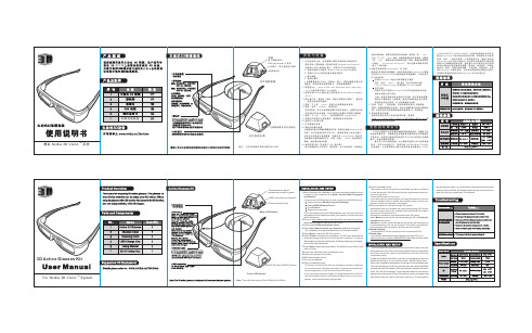
U s e r’s M a n u a lv1.00© 2022VERSITRON, Inc.83 Albe Drive / Suite CNewark, DE 19702Copyright VERSITRON, Inc. All rights reserved. All brand and product names are trademarks or registered trademarks of their respective companies.PROPRIETARY DATAAll data in this manual is proprietary and may not be disclosed,used or duplicated, for procurement or manufacturing purposes,without prior written permission by VERSITRON.VERSITRON LIFETIME WARRANTYAll VERSITRON products are covered by a Lifetime Warranty against defects in materials and workmanship. This coverage is applicable to the original purchaser and is not transferable.We repair, or at our option, replace parts/products that, during normal usage and operation, are proven to be defective during the time you own the products, provided that said products and parts are still manufactured and/or available. Such repair/replacement is subsequent to receipt of your product at our facility and our diagnostic evaluation and review of the unit. Advance replacements are not provided as part of the warranty coverage.This warranty does not cover damage to products caused by misuse, mishandling, power surges, accident, improper installation, neglect, alteration, improper maintenance, or other causes which are not normal and customary applications of the products and for which they were not intended. No other warranty is expressed or implied, and VERSITRON is not liable for direct, indirect, incidental or consequential damages or losses.In the unlikely event a warranty issue should arise, simply contact us at 302-894-0699 or************************************************************************ Authorization (RMA) number, along with instructions for returning your product.Product OverviewThis installation manual describes the installation procedures of the following VERSITRON Industrial Media Converter products:For efficient and reliable connectivity from the network edge device to a backbone switch or server, the Fast Ethernet and Gigabit Media Converters are designed to extend existing LANs over fiber optic cable.These MF7260P PoE/PoE+ converter provides optimized deployment and reliable power management to PoE edge devices such as IP surveillance cameras, access control panels, wireless access points or Voice over IP phones. Full power POE-af (15.4w) /POE-at (30w) is applied to the copper port.This installation manual describes how to install and use the Industrial Media Converters. “Industrial Media Converter” is used as an alternative name for the above products in this user’s manual.Packet ContentsOpen the box of the Industrial Media Converter and carefully unpack it. The box should contain the following items:If any of these are missing or damaged, please contact VERSITRON immediately; if possible, retain the carton including the original packing material, and use them again to repack the product in case there is a need to return it to us for repair.Unpacking, Inspecting, and Storing⑥ Removing the transport packagingExamine the delivered product thoroughly to ensure that the product has not been damaged during transportation. Remove the transport packing carefully.⑥ Identifying the productLocate the model number of the product from the label the on surface of the product box and check against the ordering information to verify that the received product is correct.⑥ Inspecting the productCheck the product carefully to see if any damage occurred during the transportation. Notify VERSITRON immediately if there are any discrepancies or damage.⑥ StoringIf the product is stored before installation, it must be done with the original transport packaging in a dry and dust free environment.Product Features⑥Physical Ports▪10/100Base-TX Fast Ethernet or 10/100/1000BASE-T RJ45 copper▪1000BASE- SFP Slot⑥Technical Features▪Non-blocking store-and-forward switching▪RJ45 Port Supports 10/100Mbps or 10/100/1000Mbps-Full/Half-duplex Auto-negotiation▪Prevents Packet Loss w/Back Pressure (Half-Duplex) and IEEE 802.3x PAUSE Frame Flow Control (Full-Duplex)▪Available for ST, SC or LC fiber connector▪Available for operation over single mode or multimode fiber over a variety of link budget▪Available for operation over 1 or 2 fibers▪Available for operation in Ring or point-to-point configuration▪Redundant dual power supply inputs 48/52 VDC⑥PoE Features (MF7260P)▪Complies w/IEEE 802.3-af/ w/IEEE 802.3-at Power over Ethernet End-Span PSE▪Supports PoE power up to 15.4/30 watts for each PoE port▪Auto detects power device (PD)▪Remote power feeding up to 100mIndustrial Case and Installation▪IP44-rated aluminum case protection ▪Standard DIN rail design▪Redundant dual power supply inputs ▪4KV Ethernet Surge Protection▪-40°C to 80°C operating temperature Product SpecificationsPhysical DimensionsFront PanelMF7273 (ST)MF7274 (SC) MF7275-2 (SC)MF7275-2SFA (SC) MF7275-2SFB (SC)MF7260 (SFP)MF7260P (SFP)This section describes the hardware features and installation procedures of Industrial Media Converter. For easier management and operation of the product, familiarize yourself with its LED indicators and ports. Front panel illustration in this chapter display LED indicators. Please read this chapter carefully before connecting any network device to the Industrial Media Converter. ⑥LED Indicators⑥Power Input Assignment▪Insert the upper lip of the DIN rail into the DIN-rail mounting kit. Push the front of the Media Converter toward the mounting surface until it audibly snaps into place.▪Make sure that the Media Converter is attached securely to DIN rail.▪Dismantling: Lightly press down and pull out the lower edge and then remove the Media Converter from the DIN rail.Installation StepsStep 1: Unpack the Industrial Media ConverterStep 2: Check the DIN-Rail that is pre-installed on the Industrial Media Converter.(Please refer to DIN-Rail Mounting section for DIN-Rail installation).Step 3: Connect the copper Ethernet port of the Industrial Media Converter to a PC or other Ethernet device with a network cable (straight through Category 5 or above cable). Step 4: For single fiber or dual fiber SC/ST models, connect the fiber cable to the SC/ST connector of the fiber ports of the media converter.For SFP models, insert the appropriate SFP module into the SFP port. Connect the fiber cable to the LC connector of the SFP installed into the media converter.Step 5: Power on the Industrial Media Converter (Please refer to the Power Input Assignment Section for power input wiring). All the LEDs on the media converter will flash on andthen off which means the unit has been reset successfully. Then please refer to the LED Indicators section for meaning of LED lights.Step 6:When all connections are set and all LED lights show normal, the installation is complete.Notice:▪Do not place any heavy objects on the top of media converters and ensure that the media converter always has good ventilation. Do not block the ventilation holes on each side of the media converter.▪Please power off before plugging in the power cord or removing the power adapters.。
DirectX中文手册Microsoft老王翻译Alpha整理alpha_nuaa@目录第一章DirectX基础(初级篇)第一节什么是DirectX一、什么是DirectX ?二、DirectX的组成部分三、关于DirectDraw四、为什么要使用DirectDraw?五、DirectX5.0的新特性?六、什么是部件对象模型(COM)七、自我检测第二节如何安装和使用DirectX一、编译库和运行库二、安装VC++ 5.0三、安装DirectX5.0 的SDK四、DirectX 5.0 的文件说明五、卸载DirectX第三节一个DirectDraw入门程序一、一个小测验二、牛刀小试三、分析代码1)程序结构2)定义和创建DirectDraw对象3)设置控制级和显示模式4)创建主页面5)输出文字6)释放对象7)主窗口类型四、小结第四节DirectDraw图形编程基础知识一、像素和分辨率二、RGB色彩三、设备无关位图(DIB)四、位深度(Bit depth)五、抖动处理(Dithering)六、调色板(Palette)七、GDI与DirectDraw八、位块传送(Blit)九、翻页(Page flipping)十、矩形(Rectangle)十一、精灵动画(Sprite animation)十二、关键色(Color Key)十三、补丁(Patching)十四、范围检查与碰撞检测第二章DirectDraw核心(高级篇)第一节、DirectDraw架构一、DirectDraw结构概览二、DirectDraw对象类型三、硬件抽象层(HAL)四、软件仿真层(HEL)五、系统集成第二节、控制级第三节显示模式一、关于显示模式二、测定支持的显示模式三、设置显示模式四、恢复显示模式五、Mode X和Mode 13显示模式六、对高分辨率和真彩色的支持第四节DirectDraw对象一、什么是DirectDraw对象?二、IDirectDraw2接口的新特性?三、单进程的多DirectDraw对象四、使用CoCreateInstance创建DirectDraw对象第五节页面一、页面的基本概念1)什么是页面2)页面接口3)宽度和宽距4)关键色5)像素格式二、创建页面1)创建主页面2)创建离屏页面3)创建复杂页面和换页链4)创建超宽页面三、换页四、页面丢失五、释放页面六、更新页面属性七、直接访问帧缓存八、使用非本地视频RAM页面九、色彩和格式转换十、覆盖页面1)覆盖页面概览2)DDCAPS的重要成员和标志3)源和目标矩形4)边界和大小限制5)最小和最大缩放系数6)覆盖页面关键色7)覆盖页面的定位8)创建覆盖页面9)覆盖页面的Z轴次序10)覆盖页面的换页十一、Blit到多窗口第六节调色板一、什么是调色板?二、调色板的种类三、对非主页面设置调色板四、共享调色板五、调色板动画第七节裁减器一、什么是“裁减器(Clipper)”对象二、裁减清单(Clip list)三、共享DirectDrawClipper对象四、独立的DirectDrawClipper对象五、用CoCreateInstance创建DirectDrawClipper对象六、对系统鼠标使用裁减器七、对多窗口使用Clipper第八节多显示器系统一、在多显示器系统中列举显示设备二、焦点窗口和设备窗口三、设置焦点窗口和设备窗口四、缺省设备窗口五、多显示器系统中的显示设备与加速特性第九节、高级DirectDraw主题一、对Mode 13的支持1)关于Mode 132)设置Mode 133)Mode 13与页面特性4)使用Mode 13模式二、从DMA中获益1)关于DMA设备支持2)对DMA支持的检测3)典型的DMA方案4)利用DMA三、在窗口模式下使用调色板1)窗口模式的调色板入口类型2)在窗口模式下创建调色板3)在窗口模式下设置调色板入口四、获得换页和Blit操作的状态五、使用Blit进行单色填充六、测定显示硬件的能力七、在视频RAM中储存位图八、Triple Buffering(三缓冲)九、DirectDraw应用程序和窗口风格十、将真彩色匹配到帧缓冲区的色彩空间第一章DirectX基础(初级篇)第一节什么是DirectX?一、什么是DirectX微软的DirectX软件开发工具包(SDK)提供了一套优秀的应用程序编程接口(APIs),这个编程接口可以提供给你开发高质量、实时的应用程序所需要的各种资源。