德国倍加福超声波传感器UC6000-30GM
- 格式:pdf
- 大小:556.17 KB
- 文档页数:3
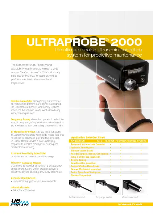
ULTRAPROBE ®2000re-sponse for enhanced leak and fault detection.2) Linear Mode provides a slow, averaging response to stabilize readings for bearing and mechanical monitoring.A 10-turn Sensitivity Adjust Dialprovides a wide dynamic sensitivity range.Trisonic ™ Scanning Modulea patented transducer, consists of a phased array of three transducers, which provides a level of sensitivity beyond anything previously obtainable.Acoustic Headphones:• Noise isolating type for loud environments.Intrinsically Safe:• FM, CSA, ATEX ratedThe ultimate analog ultrasonic inspectionsystem for predictive maintenancePressure & Vacuum Leak Detection Hydraulic Valve Bypass Exhaust System LeaksHeat Exchangers, Boilers, Condensers Valve & Steam Trap Inspection Bearing TestingGear/Gear Box Inspection Tanks, Pipes, Leak Testing, etc.Electrical Inspection••••••••••••••••••• ••••••••APPLICATION KIT # UP2000KT U P2000SC U P2000C U P2000SStethoscope moduleLong range moduleClose focus moduleUltrasonic CD Training Series is IncludedThis professionally produced series was shot in actual plant environments enabling you to see, hear and experience realistic test examples along with practical solu-tions. The training series is applicable for all levels of ultrasonic testing experience and is arranged in an organized format. You’ll be taken step by step through each application. The following sections are included in the CD's:• Introduction to Airborne Ultrasound • Review of each Ultraprobe Feature • O verview of the Specific Application (Leak Detection, Mechanical andBearing Inspection, Heat Exchangers, Boilers & Condensers, Steam Traps & Valves, Electrical Inspection)• Demonstration of Testing Techniques • Problem Solving TechniquesConstruction Circuitry Frequency ResponseProbesTransmitter HeadsetIndicatorsBattery FeaturesOverall SizeSensitivity Threshold*Warranty Display ModesHand-held metered pistol type made with aluminum and ABS plasticSolid State heterodyne receiver with temperature compensation Frequency Detect ultrasonic frequencies between 20 kHz and 100 kHz, continuously variableFrequencies are converted to 50 kHz to 3 kHz audioScanning Module patented Trisonic plug-in type consisting of a phased array of multiple transducers for airborne ultrasound. This probe is shielded against RF interference.Rubber Focusing Probe (flexible) slips over scanning module to concentrate conical directivity and to shield reception of stray ultrasound. Also fits over Stethoscope Module to shield against high ambient ultrasound while unit isat maximum sensitivity.Stethoscope Module – plug-in type, insulated probe with RF shielding; 11.4 cm (4 1/2”) long stainless steel probe tip, conically shaped for uniform surface contact. Stethoscope Extension Kit: 3-piece, segmented metal rods to increasestethoscope contact range for 50.8 cm (20”) and 76.2 cm (31”).Patented warble tone transmissionNoise isolating type: Double headset wired monophonic. Impedance16 ohms. Over 23 dB of noise attenuation.Meets or exceeds ANSI specifications and OSHA standards. For hard hat use.Ballistic output meter; linear calibration scale of 0-100 for logging relative measurements. Meter is accurate 1% throughout entire scale. Low Level Battery LED indicator for main housing internal power supply.Self contained NiMH rechargeable.RECHARGING SYSTEM: Standard 110V . Also available in 220V .Frequency Tuning Adjustment Dial: 20-100 kHz with "fixed band" position for ultra-narrow frequency response.Bi-Modal Meter Switchfor logarithmic and linear meter scale adjustments.Optional Auxiliary Modeselection for chart recorder output: 0-50 mV .Sensitivity Control – Precision 10-turn adjustment dial with numerically calibrated sensitivity increments for finite gain adjustment.Spring loaded trigger switchComplete kit in Zero Halliburton aluminum carrying case:47 x 37 x 17 cm (18.5” x 14.5” x 6.5”)Pistol unit: 0.9 kg (2 lbs.)Complete carrying case: 6.4 kg (14 lbs.)Detects0.127mm(0.005")********************(5psi) at a distance of 15.24 m (50 ft.)1 x 10⁻² std. cc/sec to 1 x 10⁻³ std. cc/sec 1-year parts/labor standard,5 years with completed warranty registration card.Logaritmic and linear*depends on leak configuration**specify Ex rating if needed at time of orderUltraprobe ® 2000 SpecificationsUltraprobe 2000 Kit: Meets and exceeds ASTM E1002-2005 requirements for Leak Detection. Government Codes NSN: 6635-01-156-3927, FSCM (CAGE) Code: 59202. Table of allowance #s: 788, 404, 576, 583, 607. Covered by one or more of the following patents: 0151115; 0303776; 0315199; 1206586; 1297576; 1881263; 2562758; 2689339; 4416145; 4823600; 5955670; 6122966; 6339961; 6341518; 6415645; 6655214; 6707762; 6804992 UE Systems is committed to continual product improvement; therefore specifications are subject to change without notice. Warranty details are available by request.Kit includes:• F requency Selection (20 kHz – 100 kHz)• Precision edgewise meter • 3-way meter/auxiliary mode selector • N umerically calibrated 10-turn sensitivity dial • R echargeable battery with lowlevel indicator light• Anodized aluminum housing • Trisonic™ Scanning Module • Stethoscope/Contact Module • Stethoscope Extension Kit • Rubber Focusing Probe • Warble Tone Generator• Deluxe noise isolating headset • Z ero Halliburton aluminium carrying case • I nstruction Manual andMultimedia Training**UE Systems Europe • Windmolen 22 • 7609 NN Almelo • The NetherlandsT: +31(0)548-659011 • F: +31(0)548-659010 • E:*****************• www.uesystems.euwww.uesystems.eu。
• 56•随着岸桥大型化,智能化的发展,其防撞系统也需要不断升级。
本文对各种常规岸桥防撞系统进行分析研究,详细介绍了激光扫描传感器的在岸桥防撞系统的应用。
岸边集装箱起重机(以下简称岸桥)防撞系统包括大梁防撞系统和大车防撞系统。
功能是在大车运行过程中,保护大梁机构和大车机构不与障碍物碰撞。
随着船舶和岸桥大型化的发展,大梁和大车车道数量不断增加,船桅杆或雷达越来越高,同时作业的船舶、集卡数量越来越多,碰撞风险都大大增加。
而司机在司机室很难准确判断障碍物情况,就需要岸桥防撞系统发挥作用,避免碰撞事故。
岸桥防撞系统在不断发展升级,从机械、感应限位发展到激光扫描传感器(以下简称激光限位),防撞性能不断提高。
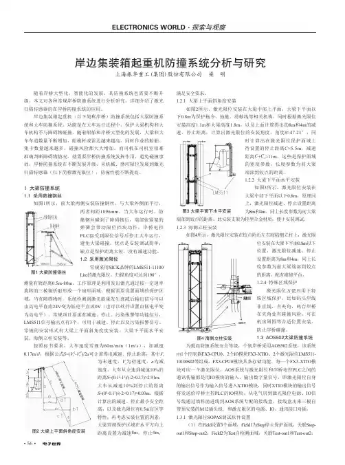
1 大梁防撞系统1.1 采用防撞钢丝如图1所示,前大梁两侧安装防撞钢丝,与大梁外侧面平行,满足安全要求。
1.2.1 大梁上平面斜角度安装如图2所示,激光限位安装在大梁中部上平面,大梁下平面以下0.8m 为保护拖令、拖链、滑触线等相关机构,同时根据激光限位安装高度1.1m 和大梁高度1.8m ,以及上面计算得出的8m 和4m 的减速、停止距离,计算出激光限位的安装角度,角度θ≈47.23°,同岸边集装箱起重机防撞系统分析与研究上海振华重工(集团)股份有限公司 梁 明图1 大梁防撞钢丝两者间距1896mm ,当大车运行时,防撞钢丝碰到了障碍物后,端部张紧架的弹簧会带动限位挡块动作,岸桥电控PLC 接受到限位信号后停止大车运行,避免大梁碰撞。
优点是安装调试简单;缺点是保护距离太短,没有减速功能。
1.2 采用激光限位常规采用SICK 品牌的LMS511-11100Lite 的激光限位,扫描角度可达到190°,测量有效距离0.5m-80m 。
工作原理是利用发出激光通过按一定速率旋转的三棱镜折射形成一个扇形面域,根据需要设置面域的保护区域,当有障碍物时,系统检测到激光能量发生衰减后输出信号可以由高电平直流24V 变为低电平直流0V (也可以软件设置由低电平变为高电平)。
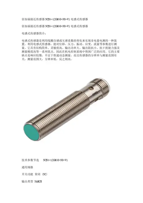
倍加福接近传感器NCB4-12GM40-N0-V1电感式传感器倍加福接近传感器NCB4-12GM40-N0-V1电感式传感器电感式传感器简介:电感式传感器是利用线圈自感或互感系数的变化来实现非电量电测的一种装置。
利用电感式传感器,能对位移、压力、振动、应变、流量等参数进行测量。
它具有结构简单、灵敏度高、输出功率大、输出阻抗小、抗干扰能力强及测量精度高等一系列优点,因此在机电控制系统中得到广泛的应用。
它的主要缺点是响应较慢,不宜于快速动态测量,而且传感器的分辨率与测量范围有关,测量范围大,分辨率低,反之则高。
技术参数节选 NCB4-12GM40-N0-V1通用规格开关功能常闭 (NC)输出类型 NAMUR额定工作距离 4 mm安装齐平确保操作距离 0 ... 3,24 mm实际工作距离 3,6 ... 4,4 mm 类型衰减系数 rAl 0,41衰减系数 rCu 0,39衰减系数 r304 0,78输出类型 2 线额定值额定电压 8,2 V (Ri 约 1 kΩ)开关频率 0 ... 1500 Hz迟滞 1 ... 15 类型 5 %反极性保护反极性保护短路保护是适用于 2:1 技术是,无需反极性保护二极管电流消耗未检测到测量板 min. 2,2 mA检测到测量板≤ 1 mA开关状态指示灯黄色多孔 LED功能性安全相关参数安全完整性级别 (SIL) SIL 2MTTFd 3010 a任务时间 (TM) 20 a诊断覆盖率 (DC) 0 %装置应用传感器作为采集和获取信息的工具,对系统的自动化检测和质量监测起着重要作用。
电感式传感器是一种互感式电感传感器,它可将微小的机械量,如位移、振动、压力造成的长度、内径、外径、不平行度、不垂直度、偏心、椭圆度等非电量物理量的几何变化转换为电信号的微小变化,转化为电参数进行测量,是一种灵敏度较高的传感器,具有结构简单可靠、输出功率大、抗阻抗能力强、对工作环境要求不高、稳定性好等一系列优点,因而被广泛应用于各种工程物理量检测与自动控制系统中 [3] 。
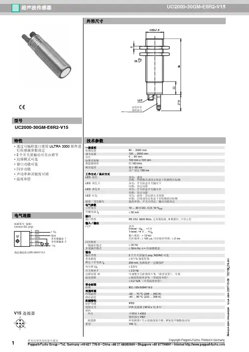
UC4000-30GM-IUR2-V15Ultrasonic sensorUC4000-30GM-IUR2-V15R e l e a s e d a t e : 2018-01-08 10:27D a t e o f i s s u e : 2018-01-09104094_e n g .x m lDimensionsElectrical ConnectionPinoutTemperature probeCoded plug52225128ø40M30x1.527.536LEDStandard symbol/Connection:(v ersion IU)Sync.Core colors in accordance with EN 60947-5-2.0-10 V 4-20 mA + U B - U B15432(BN)(GY)(BK)(BU)(WH)U134521 BN2 WH3 BU4 BK 5GYWire colors in accordance with EN 60947-5-2(brown)(white)(blue)(black)(gray)Additional Information Analogue output functionNear distance of evaluation Far distance of evaluationAnalog functionRising slopeFalling slopeZero line mode20 mA/10 V4 mA/0 V4 mA/0 V 20 mA/10 V20 mA/10 V4 mA/0 VA1= 0 mmA2R e l e a s e d a t e : 2018-01-08 10:27D a t e o f i s s u e : 2018-01-09104094_e n g .x m l Description of Sensor FunctionsProgramming procedureThe sensor features 2 programmable analog outputs with programmable evaluation range. Programming the evaluation range and the operating mode is done either via the sensor's RS232 interface and ULTRA3000 software (see the ULTRA3000 software description) or by means of the programming plug at the sensor's back end which is described here.Programming of Evaluation Range1.Disconnect supply voltage2.Remove the programming plug to activate program mode.3.Reconnect supply voltage (Reset)4.Place the target at the desired position for A15.Momentarily insert the programming plug in position A1 and then remove. This will program the position A1.6.Place the target at the desired position for A27.Momentarily insert the programming plug in position A2 and then remove. This will program the position A2.Notes:•Removing the programming plug saves the new position into the device memory.•The programming status is indicated by the LED. A flashing green LED indicates that the target is detected; a flashing red LED indicates that no target is detected.Programming the Operation ModeIf the program mode is still activated, continue at number 4. If not, activate program mode by performing the sequence numbers 1 to 3.1.Disconnect supply voltage2.Remove the programming plug to activate program mode.3.Reconnect supply voltage (Reset)4.Insert the programming plug in position E2/E3. By removing and reinserting the plug, the user can toggle through the three different modes of operation. The selected mode is indicated by the LEDs as shown below:•Rising slope mode, LED A2 flashes •Falling slope mode, LED A1 flashes •Zero line mode, LEDs A1 and A2 flash5.Once the desired mode is selected, insert the programming plug in position T. This completes the programming procedure and saves the switch points and mode of operation.6.The sensor now operates in normal mode.Note:The programming plug also functions as the temperature compensation. If the programming plug has not been inserted in the T position within 5minutes, the sensor will return to normal operating mode with the latest saved values, without temperature compensation.Factory settings See technical data.DisplayThe sensor provides LEDs to indicate various conditions.Mounting flange, 30 mmBF 30-FMounting flange with dead stop, 30 mm UC-30GM-PROGULTRA3000Software for ultrasonic sensors, comfort line UC-30GM-R2DA5-IU-2K-VProcess control and indication equipment V15-G-2M-PVCFemale cordset, M12, 5-pin, PVC cableA2R e l e a s e d a t e : 2018-01-08 10:27D a t e o f i s s u e : 2018-01-09104094_e n g .x m lSynchronizationThis sensor features a synchronization input for suppressing ultrasonic mutual interference ("cross talk"). If this input is not connected, the sensor will operate using internally generated clock pulses. It can be synchronized by applying an external square wave. The pulse duration must be ≥100 µs. Each falling edge of the synchronization pulse triggers transmission of a single ultrasonic pulse. If the synchronization signal remains low for ≥ 1 second, the sensor will revert to normal operating mode. Normal operating mode can also be activated by opening the signal connection to the synchronization input (see note below).If the synchronization input goes to a high level for > 1 second, the sensor will switch to standby mode, indicated by the green LED. In this mode,the outputs will remain in the last valid output state.Note:If the option for synchronization is not used, the synchronization input has to be connected to ground (0 V) or the sensor must be operated via a V1 cordset (4-pin).The synchronization function cannot be activated during programming mode and vice versa.The following synchronization modes are possible:1.Several sensors (max. number see technical data) can be synchronized together by interconnecting their respective synchronization inputs.In this case, each sensor alternately transmits ultrasonic pulses in a self multiplexing mode. No two sensors will transmit pulses at the same time (see note below).2.Multiple sensors can be controlled by the same external synchronization signal. In this mode the sensors are triggered in parallel and are syn-chronized by a common external synchronization pulse.3.A separate synchronization pulse can be sent to each individual sensor. In this mode the sensors operate in external multiplex mode (see notebelow).4.A high level (+U B ) on the synchronization input switches the sensor to standby mode.Note:Sensor response times will increase proportionally to the number of sensors that are in the synchronization string. This is a result of the multiplex-ing of the ultrasonic transmit and receive signal and the resulting increase in the measurement cycle time.Note on communication with the UC-30GM-R2 interface cableThe UC-30GM-R2 interface cable allows for communication with the ultrasonic sensor using ULTRA3000 software. The cable creates a connection between a PC RS-232 interface and the programming plug socket on the sensor. When connecting to the sensor, make certain the plug is lined up correctly; otherwise no communication will be possible. The key of the cable’s plug must be aligned to the groove of the socket on the sensor (not with the arrow symbol on the sen-sor).Programmable parameters with the ULTRA3000 software •Evaluation limits A1 and A2•Operation mode •Sonic speed•Temperature offset (The inherent temperature-rise of the sensor can be considered in the temperature compensation)•Expansion of the unusable area (for suppression of unusable area echoes)•Reduction of the detection range (for suppression of remote range echoes)•Time of measuring cycle•Acoustic power (interference of the burst duration)•Sensitivity•Behavior of the sensor in case of echo loss •Behavior of the sensor in case of a fault•Average formation via an allowed number of measuring cycles •Selection of the parameter set, RS 232 or manually Note:When connected to a PC and running the ULTRA3000 software, the sensor can act as a long term data logger as well.Green LEDRed LED Yellow LED A1Yellow LED A2During Normal Operation - Temperature compensated - with removed programming plug Interference (e.g. compressed air)On Off Off Off On Flashing Object in evaluation range Object in evaluation range remains in previous stateObject in sensing range Object in sensing range remains in previous stateDuring Sensor Programming Evaluation limit A1: Object detected No object detected Evaluation limit A2: Object detected No object detected Operation mode: Rising slope mode Falling slope mode Zero line mode Flashing Off Flashing Off On On On Off Flashing Off Flashing Off Off Off Flashing Flashing Off OffOff Flashing FlashingOff Off Flashing Flashing Flashing Off FlashingStandbyFlashingOffremains in previous stateremains in previous stateR e l e a s e d a t e : 2018-01-08 10:27D a t e o f i s s u e : 2018-01-09104094_e n g .x m lInstallation conditionsIf the sensor is installed in an environment where the temperature can fall below 0 °C, one of these mounting flanges must be used for mounting:BF30, BF30-F, or BF 5-30.If the sensor is mounted in a through hole using the included steel nuts, it must be mounted at the middle of the threaded housing. If it must be mounted at the front end of the threaded housing, plastic nuts with centering ring (optional accessories) must be used.UC4000-30GM-IUR2-V15。
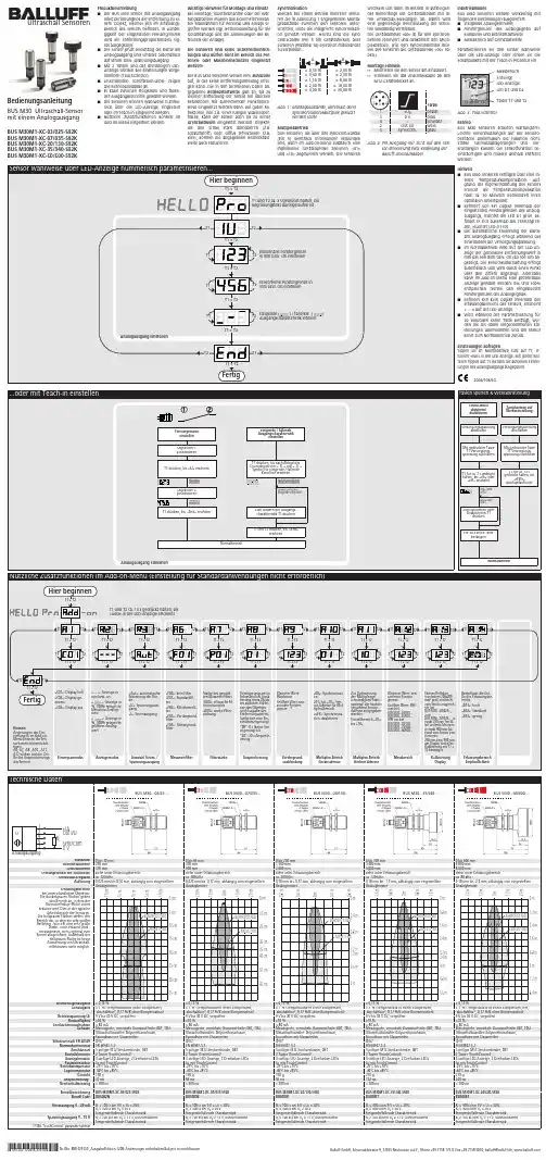
0 bis 30 mm 0 bis 65 mm siehe unter Erfassungsbereich siehe unter Erfassungsbereich 0 bis 200 mm 1.300 mm 0 bis 350 mm 3.400 mm 2.000 mmsiehe unter Erfassungsbereich 5.000 mmsiehe unter Erfassungsbereich 0 bis 600 mm 6.000 mm 8.000 mmsiehe unter Erfassungsbereich ca. 320 kHz0,025 mm bis 0,10 mm, abhängig vom eingestellten ca. 400 kHz0,025 mm bis 0,17 mm, abhängig vom eingestellten AnalogfensterAnalogfenster% (Temperaturdrift intern kompensiert, % (Temperaturdrift intern kompensiert, abschaltbar , 0,17 %/K ohne Kompensation)9 V bis 30 V DC, verpolfest abschaltbar , 0,17 %/K ohne Kompensation)9 V bis 30 V DC, verpolfest ca. 200 kHz0,18 mm bis 0,57 mm, abhängig vom eingestellten ca. 120 kHz0,18 mm bis 1,5 mm, abhängig vom eingestellten AnalogfensterAnalogfensterca. 80 kHz0,18 mm bis 2,4 mm, abhängig vom eingestellten Analogfenster% (Temperaturdrift intern kompensiert,± 0,15 %% (Temperaturdrift intern kompensiert, abschaltbar , 0,17 %/K ohne Kompensation))9 V bis 30 V DC, verpolfest abschaltbar , 0,17 %/K ohne Kompensation)9 V bis 30 V DC, verpolfest ± 0,15 %± 1 % (Temperaturdrift intern kompensiert,iert, abschaltbar , 0,17 %/K ohne Kompensation)9 V bis 30 V DC, verpolfest Messingrohr, vernickelt; Kunststoffteile: PBT, TPU;Ultraschallwandler: Polyurethanschaum,Messingrohr, vernickelt; Kunststoffteile: PBT, TPU;Ultraschallwandler: Polyurethanschaum,Epoxidharz mit Glasanteilen Epoxidharz mit Glasanteilen EN 60947-5-25-poliger M12-Steckverbinder, PBT EN 60947-5-25-poliger M12-Steckverbinder, PBT ±10 % 80 mAMessingrohr, vernickelt; Kunststoffteile: PBT, TPU;Ultraschallwandler: Polyurethanschaum,Messingrohr, vernickelt; Kunststoffteile: PBT, TPU;Ultraschallwandler: Polyurethanschaum,±10 %≤ 80 mAMessingrohr, vernickelt; Kunststoffteile: PBT, TPU;Ultraschallwandler: Polyurethanschaum,Epoxidharz mit Glasanteilen Epoxidharz mit Glasanteilen IP 67EN 60947-5-25-poliger M12-Steckverbinder, PBT EN 60947-5-25-poliger M12-Steckverbinder, PBT Epoxidharz mit Glasanteilen IP 67EN 60947-5-25-poliger M12-Steckverbinder, PBT 2 Taster (TouchControl)3-stellige LED-Anzeige, 2 Dreifarben-LEDs 2 Taster (TouchControl)3-stellige LED-Anzeige, 2 Dreifarben-LEDs Ja, mit TouchControl -25°C bis +70°C Ja, mit TouchControl -25°C bis +70°C -40°C bis +85°C -40°C bis +85°C 2 Taster (TouchControl)3-stellige LED-Anzeige, 2 Dreifarben-LEDs 2 Taster (TouchControl)3-stellige LED-Anzeige, 2 Dreifarben-LEDs Ja, mit TouchControl -25°C bis +70°C Ja, mit TouchControl -25°C bis +70°C 2 Taster (TouchControl)3-stellige LED-Anzeige, 2 Dreifarben-LEDs Ja, mit TouchControl -25°C bis +70°C -40°C bis +85°C -40°C bis +85°C 210 g 172 ms < 300 ms-40°C bis +85°C 270 g 240 ms < 300 msBUS M30M1-XC-03/025-S92K BUS M30M1-XC-07/035-S92K Ω bei 9 V ≤ U ≤ 20 V;Ω bei U ≥ 20 VΩ bei 9 V ≤ U ≤ 20 V;Ω bei U ≥ 20 VSteigende/fallende CharakteristikΩ bei U ≥ 15 V, kurzschlussfest Steigende/fallende CharakteristikΩ bei U ≥ 15 V, kurzschlussfest BUS M30M1-XC-20/130-S92K BUS M30M1-XC-35/340-S92K BUS003TBUS M30M1-XC-60/600-S92K BUS0041Ω bei 9 V ≤ U ≤ 20 V;Ω bei U ≥ 20 V100 Ω bei 9 V ≤ U ≤ 20 V; 500 Ω bei U ≥ 20 VSteigende/fallende Charakteristik100 k Ω bei U ≥ 15 V, kurzschlussfest Steigende/fallende Charakteristik100 k Ω bei U ≥ 15 V, kurzschlussfest R ≤ 100 Ω bei 9 V ≤ U ≤ 20 V;R ≤ 500 Ω bei U ≥ 20 VSteigende/fallende CharakteristikR ≥ 100 k Ω bei U ≥ 15 V, kurzschlussfest Steigende/fallende CharakteristikSteigende/fallende CharakteristikSteigende/fallende CharakteristikSteigende/fallende CharakteristikSteigende/fallende Charakteristikausgerichtete PlatteRohr ø 10 mm5 c m0 c m5 c m10 c mausgerichtete PlatteRohr ø 27 mm10 c m0 c m10 c m20 c mausgerichtete PlatteRohr ø 27 mm0,4 m0 m0,4 m0,8 m0 m0,8 m1,6 m2,4 m 3,2 m 4 m 4,8 m 5,6 m 3,4 mausgerichtete PlatteRohr ø 27 mm1,6 m0,8 m0 m0,8 m1,6 m0 m 1,2 m2,4 m3,6 m4,8 m6 m7,2 m8,4 mausgerichtete PlatteRohr ø 27 mm2,4 m1,2 m0 m1,2 m2,4 mSensor wahlweise über LED-Anzeige nummerisch parametrisieren...BedienungsanleitungBUS M30 Ultraschall-Sensor mit einem AnalogausgangBUS M30M1-XC-03/025-S92K BUS M30M1-XC-07/035-S92K BUS M30M1-XC-20/130-S92K BUS M30M1-XC-35/340-S92K BUS M30M1-XC-60/600-S92KUltraschall SensorenSet sensor parameters alternatively numerically using LED-display...Instruction manualBUS M30 Ultrasonic Sensor with one analogue outputBUS M30M1-XC-03/025-S92K BUS M30M1-XC-07/035-S92K BUS M30M1-XC-20/130-S92K BUS M30M1-XC-35/340-S92K BUS M30M1-XC-60/600-S92K0 to 30 mm 0 to 65 mm Please see detection zone Please see detection zone 0 to 200 mm 1.300 mm 0 to 350 mm 3.400 mm 2.000 mmPlease see detection zone 5.000 mmPlease see detection zone 0 to 600 mm 6.000 mm 8.000 mmPlease see detection zone 0,025 mm to 0,10 mm, depending on the 0,025 mm to 0,17 mm, depending on the analogue windowanalogue window± 0,15 %± 1 % (Temperature drift internal compensated,± 0,15 %± 1 % (Temperature drift internal compensated,may be deactivated , 0,17%/K without compensation)9 V to 30 V DC, short-circuit-proof may be deactivated , 0,17%/K without compensation)9 V to 30 V DC, short-circuit-proof 0,18 mm to 0,57 mm, depending on the 120 kHz0,18 mm to 1,5 mm, depending on the analogue windowanalogue window80 kHz0,18 mm to 2,4 mm, depending on the analogue window± 0,15 %± 1 % (Temperature drift internal compensated,± 0,15 %± 1 % (Temperature drift internal compensated,may be deactivated , 0,17%/K without compensation)9 V to 30 V DC, short-circuit-proof may be deactivated , 0,17%/K without compensation)9 V to 30 V DC, short-circuit-proof ± 0,15 %± 1 % (Temperature drift internal compensated,may be deactivated , 0,17%/K without compensation)9 V to 30 V DC, short-circuit-proof 80 mA80 mABrass sleeve, nickel-plated, plastic parts: PBT, TPU;Ultrasonic transducer: polyurethane foam,Brass sleeve, nickel-plated, plastic parts: PBT, TPU;Ultrasonic transducer: polyurethane foam,epoxy resin with glass content epoxy resin with glass content EN 60947-5-25-pin plug, PBTEN 60947-5-25-pin plug, PBT±10 % 80 mABrass sleeve, nickel-plated, plastic parts: PBT, TPU;Ultrasonic transducer: polyurethane foam,Brass sleeve, nickel-plated, plastic parts: PBT, TPU;Ultrasonic transducer: polyurethane foam,±10 %≤ 80 mABrass sleeve, nickel-plated, plastic parts: PBT, TPU;Ultrasonic transducer: polyurethane foam,epoxy resin with glass content epoxy resin with glass content IP 67EN 60947-5-25-pin plug, PBTEN 60947-5-25-pin plug, PBTepoxy resin with glass content IP 67EN 60947-5-25-pin plug, PBT2 push-buttons (TouchControl)3-digit LED-display, 2 three-colour LEDs 2 push-buttons (TouchControl)3-digit LED-display, 2 three-colour LEDs Yes, with TouchControl -25°C to +70°C Yes, with TouchControl -25°C to +70°C -40°C to +85°C -40°C to +85°C < 300 ms< 300 ms2 push-buttons (TouchControl)3-digit LED-display, 2 three-colour LEDs 2 push-buttons (TouchControl)3-digit LED-display, 2 three-colour LEDs Yes, with TouchControl -25°C to +70°C Yes, with TouchControl -25°C to +70°C 2 push-buttons (TouchControl)3-digit LED-display, 2 three-colour LEDs Yes, with TouchControl -25°C to +70°C -40°C to +85°C -40°C to +85°C 210 g < 300 ms172 ms < 300 ms-40°C to +85°C 270 g 240 ms < 300 msBUS M30M1-XC-03/025-S92K BUS M30M1-XC-07/035-S92K BUS002N100 Ω at 9 V ≤ U ≤ 20 V;BUS005K100 Ω at 9 V ≤ U ≤ 20 V; 500 Ω at U ≥ 20 VRising/falling output characteristic500 Ω at U ≥ 20 VRising/falling output characteristic100 k Ω at U ≥ 15 V, short-circuit-proof Rising/falling output characteristic100 k Ω at U ≥ 15 V, short-circuit-proof Rising/falling output characteristicBUS M30M1-XC-20/130-S92K BUS M30M1-XC-35/340-S92K BUS003F100 Ω at 9 V ≤ U ≤ 20 V;BUS003T≤ 100 Ω at 9 V ≤ U ≤ 20 V;BUS M30M1-XC-60/600-S92K BUS0041R ≤ 100 Ω at 9 V ≤ U ≤ 20 V; 500 Ω at U ≥ 20 VRising/falling output characteristic≤ 500 Ω at U ≥ 20 VRising/falling output characteristic100 k Ω at U ≥ 15 V, short-circuit-proof Rising/falling output characteristic≥ 100 k Ω at U ≥ 15 V, short-circuit-proof Rising/falling output characteristicR ≤ 500 Ω at U ≥ 20 VRising/falling output characteristicR ≥ 100 k Ω at U ≥ 15 V, short-circuit-proof Rising/falling output characteristicausgerichtete Platte Rohr ø 10 mm 5 c m0 c m5 c m10 c mPlateRound barausgerichtete Platte Rohr ø 27 mm10 c m0 c m10 c m20 c mPlateRound bar ausgerichtete Platte Rohr ø 27 mm 0,4 m0 m0,4 m0,8 mPlateRound bar0 m0,8 m1,6 m2,4 m3,2 m 4 m4,8 m5,6 m3,4 mausgerichtete Platte Rohr ø 27 mm 1,6 m0,8 m0 m0,8 m1,6 mPlateRound bar0 m 1,2 m 2,4 m 3,6 m 4,8 m 6 m 7,2 m 8,4 mausgerichtete Platte Rohr ø 27 mm2,4 m1,2 m0 m1,2 m2,4 mPlateRound bar Ultrasonic SensorsUltraschall SensorenBedienungsanleitungBUS M30 Ultraschall-Sensormit einem AnalogausgangBUS M30M1-XC-03/025-S92KBUS M30M1-XC-07/035-S92KBUS M30M1-XC-20/130-S92KBUS M30M1-XC-35/340-S92KBUS M30M1-XC-60/600-S92KSensor wahlweise über LED-Anzeige nummerisch parametrisieren...0 bis 30 mm 0 bis 65 mm siehe unter Erfassungsbereich siehe unter Erfassungsbereich 0 bis 200 mm 1.300 mm 0 bis 350 mm 3.400 mm 2.000 mmsiehe unter Erfassungsbereich 5.000 mmsiehe unter Erfassungsbereich 0 bis 600 mm 6.000 mm 8.000 mmsiehe unter Erfassungsbereich ca. 320 kHz0,025 mm bis 0,10 mm, abhängig vom eingestellten ca. 400 kHz0,025 mm bis 0,17 mm, abhängig vom eingestellten AnalogfensterAnalogfenster% (Temperaturdrift intern kompensiert, % (Temperaturdrift intern kompensiert, abschaltbar , 0,17 %/K ohne Kompensation)9 V bis 30 V DC, verpolfest abschaltbar , 0,17 %/K ohne Kompensation)9 V bis 30 V DC, verpolfest ca. 200 kHz0,18 mm bis 0,57 mm, abhängig vom eingestellten ca. 120 kHz0,18 mm bis 1,5 mm, abhängig vom eingestellten AnalogfensterAnalogfensterca. 80 kHz0,18 mm bis 2,4 mm, abhängig vom eingestellten Analogfenster% (Temperaturdrift intern kompensiert,± 0,15 %% (Temperaturdrift intern kompensiert, abschaltbar , 0,17 %/K ohne Kompensation))9 V bis 30 V DC, verpolfest abschaltbar , 0,17 %/K ohne Kompensation)9 V bis 30 V DC, verpolfest ± 0,15 %± 1 % (Temperaturdrift intern kompensiert,iert, abschaltbar , 0,17 %/K ohne Kompensation)9 V bis 30 V DC, verpolfest Messingrohr, vernickelt; Kunststoffteile: PBT, TPU;Ultraschallwandler: Polyurethanschaum,Messingrohr, vernickelt; Kunststoffteile: PBT, TPU;Ultraschallwandler: Polyurethanschaum,Epoxidharz mit Glasanteilen Epoxidharz mit Glasanteilen EN 60947-5-25-poliger M12-Steckverbinder, PBT EN 60947-5-25-poliger M12-Steckverbinder, PBT ±10 % 80 mAMessingrohr, vernickelt; Kunststoffteile: PBT, TPU;Ultraschallwandler: Polyurethanschaum,Messingrohr, vernickelt; Kunststoffteile: PBT, TPU;Ultraschallwandler: Polyurethanschaum,±10 %≤ 80 mAMessingrohr, vernickelt; Kunststoffteile: PBT, TPU;Ultraschallwandler: Polyurethanschaum,Epoxidharz mit Glasanteilen Epoxidharz mit Glasanteilen IP 67EN 60947-5-25-poliger M12-Steckverbinder, PBT EN 60947-5-25-poliger M12-Steckverbinder, PBT Epoxidharz mit Glasanteilen IP 67EN 60947-5-25-poliger M12-Steckverbinder, PBT 2 Taster (TouchControl)3-stellige LED-Anzeige, 2 Dreifarben-LEDs 2 Taster (TouchControl)3-stellige LED-Anzeige, 2 Dreifarben-LEDs Ja, mit TouchControl -25°C bis +70°C Ja, mit TouchControl -25°C bis +70°C -40°C bis +85°C -40°C bis +85°C 2 Taster (TouchControl)3-stellige LED-Anzeige, 2 Dreifarben-LEDs 2 Taster (TouchControl)3-stellige LED-Anzeige, 2 Dreifarben-LEDs Ja, mit TouchControl -25°C bis +70°C Ja, mit TouchControl -25°C bis +70°C 2 Taster (TouchControl)3-stellige LED-Anzeige, 2 Dreifarben-LEDs Ja, mit TouchControl -25°C bis +70°C -40°C bis +85°C -40°C bis +85°C 210 g 172 ms < 300 ms-40°C bis +85°C 270 g 240 ms < 300 msBUS M30M1-XC-03/025-S92K BUS M30M1-XC-07/035-S92K Ω bei 9 V ≤ U ≤ 20 V;Ω bei U ≥ 20 VΩ bei 9 V ≤ U ≤ 20 V;Ω bei U ≥ 20 VSteigende/fallende CharakteristikΩ bei U ≥ 15 V, kurzschlussfest Steigende/fallende CharakteristikΩ bei U ≥ 15 V, kurzschlussfest BUS M30M1-XC-20/130-S92K BUS M30M1-XC-35/340-S92K BUS003TBUS M30M1-XC-60/600-S92K BUS0041Ω bei 9 V ≤ U ≤ 20 V;Ω bei U ≥ 20 V100 Ω bei 9 V ≤ U ≤ 20 V; 500 Ω bei U ≥ 20 VSteigende/fallende Charakteristik100 k Ω bei U ≥ 15 V, kurzschlussfest Steigende/fallende Charakteristik100 k Ω bei U ≥ 15 V, kurzschlussfest R ≤ 100 Ω bei 9 V ≤ U ≤ 20 V;R ≤ 500 Ω bei U ≥ 20 VSteigende/fallende CharakteristikR ≥ 100 k Ω bei U ≥ 15 V, kurzschlussfest Steigende/fallende CharakteristikSteigende/fallende CharakteristikSteigende/fallende CharakteristikSteigende/fallende CharakteristikSteigende/fallende Charakteristikausgerichtete PlatteRohr ø 10 mm5 c m0 c m5 c m10 c mausgerichtete PlatteRohr ø 27 mm10 c m0 c m10 c m20 c mausgerichtete PlatteRohr ø 27 mm0,4 m0 m0,4 m0,8 m0 m0,8 m1,6 m2,4 m 3,2 m 4 m 4,8 m 5,6 m 3,4 mausgerichtete PlatteRohr ø 27 mm1,6 m0,8 m0 m0,8 m1,6 m0 m 1,2 m2,4 m3,6 m4,8 m6 m7,2 m8,4 mausgerichtete PlatteRohr ø 27 mm2,4 m1,2 m0 m1,2 m2,4 m*103668*MV-DO-120658-356107Nr./No. 888 429 D/E, Ausgabe/Edition 1208; Änderungen vorbehalten/Subject to modification BalluffGmbH,Schurwaldstrasse9,73765Neuhausena.d.F.,Phone+497158173-0,Fax+4971585010,******************,Ultrasonic SensorsInstruction manualBUS M30 Ultrasonic Sensorwith one analogue outputBUS M30M1-XC-03/025-S92KBUS M30M1-XC-07/035-S92KBUS M30M1-XC-20/130-S92KBUS M30M1-XC-35/340-S92KBUS M30M1-XC-60/600-S92KSet sensor parameters alternatively numerically using LED-display...*103668*0 to 30 mm 0 to 65 mm Please see detection zone Please see detection zone 0 to 200 mm 1.300 mm 0 to 350 mm 3.400 mm 2.000 mmPlease see detection zone 5.000 mmPlease see detection zone 0 to 600 mm 6.000 mm 8.000 mmPlease see detection zone 0,025 mm to 0,10 mm, depending on the 0,025 mm to 0,17 mm, depending on the analogue windowanalogue window± 0,15 %± 1 % (Temperature drift internal compensated,± 0,15 %± 1 % (Temperature drift internal compensated,may be deactivated , 0,17%/K without compensation)9 V to 30 V DC, short-circuit-proof may be deactivated , 0,17%/K without compensation)9 V to 30 V DC, short-circuit-proof 0,18 mm to 0,57 mm, depending on the 120 kHz0,18 mm to 1,5 mm, depending on the analogue windowanalogue window80 kHz0,18 mm to 2,4 mm, depending on the analogue window± 0,15 %± 1 % (Temperature drift internal compensated,± 0,15 %± 1 % (Temperature drift internal compensated,may be deactivated , 0,17%/K without compensation)9 V to 30 V DC, short-circuit-proof may be deactivated , 0,17%/K without compensation)9 V to 30 V DC, short-circuit-proof ± 0,15 %± 1 % (Temperature drift internal compensated,may be deactivated , 0,17%/K without compensation)9 V to 30 V DC, short-circuit-proof 80 mABrass sleeve, nickel-plated, plastic parts: PBT, TPU;Ultrasonic transducer: polyurethane foam,Brass sleeve, nickel-plated, plastic parts: PBT, TPU;Ultrasonic transducer: polyurethane foam,epoxy resin with glass content epoxy resin with glass content EN 60947-5-25-pin plug, PBTEN 60947-5-25-pin plug, PBT80 mA±10 % 80 mABrass sleeve, nickel-plated, plastic parts: PBT, TPU;Ultrasonic transducer: polyurethane foam,Brass sleeve, nickel-plated, plastic parts: PBT, TPU;Ultrasonic transducer: polyurethane foam,±10 %≤ 80 mABrass sleeve, nickel-plated, plastic parts: PBT, TPU;Ultrasonic transducer: polyurethane foam,epoxy resin with glass content epoxy resin with glass content IP 67EN 60947-5-25-pin plug, PBTEN 60947-5-25-pin plug, PBTepoxy resin with glass content IP 67EN 60947-5-25-pin plug, PBT2 push-buttons (TouchControl)3-digit LED-display, 2 three-colour LEDs 2 push-buttons (TouchControl)3-digit LED-display, 2 three-colour LEDs Yes, with TouchControl -25°C to +70°C Yes, with TouchControl -25°C to +70°C -40°C to +85°C -40°C to +85°C < 300 ms< 300 ms2 push-buttons (TouchControl)3-digit LED-display, 2 three-colour LEDs 2 push-buttons (TouchControl)3-digit LED-display, 2 three-colour LEDs Yes, with TouchControl -25°C to +70°C Yes, with TouchControl -25°C to +70°C 2 push-buttons (TouchControl)3-digit LED-display, 2 three-colour LEDs Yes, with TouchControl -25°C to +70°C -40°C to +85°C -40°C to +85°C 210 g < 300 ms172 ms < 300 ms-40°C to +85°C 270 g 240 ms < 300 msBUS M30M1-XC-03/025-S92K BUS M30M1-XC-07/035-S92K BUS002N100 Ω at 9 V ≤ U ≤ 20 V;BUS005KΩ at 9 V ≤ U ≤ 20 V; 500 Ω at U ≥ 20 VRising/falling output characteristicΩ at U ≥ 20 VRising/falling output characteristic100 k Ω at U ≥ 15 V, short-circuit-proof Rising/falling output characteristic100 k Ω at U ≥ 15 V, short-circuit-proof Rising/falling output characteristicBUS M30M1-XC-20/130-S92K BUS M30M1-XC-35/340-S92K BUS003F100 Ω at 9 V ≤ U ≤ 20 V;BUS003T≤ 100 Ω at 9 V ≤ U ≤ 20 V;BUS M30M1-XC-60/600-S92K BUS0041R ≤ 100 Ω at 9 V ≤ U ≤ 20 V; 500 Ω at U ≥ 20 VRising/falling output characteristic≤ 500 Ω at U ≥ 20 VRising/falling output characteristic100 k Ω at U ≥ 15 V, short-circuit-proof Rising/falling output characteristic≥ 100 k Ω at U ≥ 15 V, short-circuit-proof Rising/falling output characteristicR ≤ 500 Ω at U ≥ 20 VRising/falling output characteristicR ≥ 100 k Ω at U ≥ 15 V, short-circuit-proof Rising/falling output characteristicausgerichtete Platte Rohr ø 10 mm 5 c m0 c m5 c m10 c mPlateRound barausgerichtete Platte Rohr ø 27 mm10 c m0 c m10 c m20 c mPlateRound bar ausgerichtete Platte Rohr ø 27 mm 0,4 m0 m0,4 m0,8 mPlateRound bar0 m0,8 m1,6 m2,4 m3,2 m 4 m4,8 m5,6 m3,4 mausgerichtete Platte Rohr ø 27 mm 1,6 m0,8 m0 m0,8 m1,6 mPlateRound bar0 m 1,2 m 2,4 m 3,6 m 4,8 m 6 m 7,2 m 8,4 mausgerichtete Platte Rohr ø 27 mm2,4 m1,2 m0 m1,2 m2,4 mPlateRound bar Nr./No. 888 429 D/E, Ausgabe/Edition 1208; Änderungen vorbehalten/Subject to modification BalluffGmbH,Schurwaldstrasse9,73765Neuhausena.d.F.,Phone+497158173-0,Fax+4971585010,******************,MV-DO-120658-356107。
倍加福超声波开关中文讲明书_倍加福超声波开关中文讲明书倍加福超声波开关中文讲明书1两个独立的开关量输出盲区小可设定固定干扰源抑制〔在近距离内调整声锥的宽度〕温度补偿同步功能常开/常闭可选UB2000-F42-E6-V15特性型号Releasedate:releasedateIssuedate:2007-10-09133988_CN.xml倍加福超声波开关中文讲明书倍加福超声波开关中文讲明书2功能描绘使用传感器侧面的两个按键能够进行参数设定。
超声波声锥的宽度可以以根据传感器安装位置的需要进行调整。
设置开关点用户能够根据需要设定开关点,开关点的设定顺序A1A2决定了"窗口+开关点"形式中输出窗口的工作状态〔常闭/常开〕。
A2键用来设置开关点A2,方法与上述A1设置方法类似。
"窗口+开关点"输出形式在"窗口+开关点"输出形式中,开关点A1和A2决定了开关量输出1的输出窗口的两个边界。
第三个开关点A3决定了开关量输出2的开关点。
传感器上电后的5分钟内能够进行开关点调整。
超过5分钟,假如需要更改开关点,只能重新上电后再设定需要的开关点。
输出方式设定和超声波声锥宽度调整按下A1键后再上电,上电后等待1秒钟确保传感器进入参数设定形式后松开A1键,此设定经过包含两步。
步骤1,输出功能的设定显示当前输出功能。
所有可选的输出功能能够通过连续短按A2键进行选择,每次按键后绿色LED的闪烁序列将会发生变化,进而显示不同的输出功能按下A1键2秒钟保存所选的输出形式,完成参数设定并确保传感器返回标准形式。
假如短按A1键将开场进行步骤2〔声锥宽度的选择〕。
用A1键设置开关点A1按A1键>2秒传感器进入学习形式,用户能够设定A1点将目的物放在需要设定的位置黄色LED快速闪烁表明检测到目的物。
红色LED 闪烁表明没有检测到目的物短按A1键传感器完成开关点A1的设定并保存设定值。
德国p+f倍加福超声波传感器的产品性能与特点德国p+f倍加福超声波传感器的基本原理介绍倍加福概况:——倍加福,感应技术的发明者;内安、防爆技术的开拓者;是全球自动化行业久负盛名的专业传感器公司。
总部设于德国曼海姆,分公司遍及六大洲,德国倍加福公司(P+F)是全球自动化行业中久负盛名的专业传感器公司。
倍加福作为全球自动化领域的电子传感与零部件的生产主导者,凭借不断的创新,恒久的质量保证,稳健的发展,保证了迄今六十余年的辉煌成就。
倍加福在全球范围内拥有5200名员工,位于德国,美国,新加坡,匈牙利,印度尼西亚和越南的生产基地几乎全部通过了ISO9001的质量认证。
如今,倍加福公司现已成为电气防爆和传感器技术领域中,享誉世界的开拓者和创新者。
p+f倍加福的业务开展始终聚焦在每个客户的个性化需求上:p+f倍加福满怀对自动化的热情及创新领导科技,致力于成为您现在乃至将来的合作伙伴。
p+f倍加福了解您的市场需求,提供特定的解决方案,并将其整合到您的处理流程中。
p+f倍加福拥有多种多样的产品系列,不仅能提供标准化应用的传感器,同时也为您量身定制解决方案。
数十年来,倍加福持续发展创新,以最gao质量标准发布,用于自动化科技领域的工业传感器及系统产品。
通过与p+f倍加福专家的紧密合作,您将获得迎合您特定需求的、zui理想的传感器系统!用于工厂自动化的工业传感器产品系列,以其高度创新为特点。
它由电感式,光电式,电容式,磁式和超声波传感器组成。
另外,p+f倍加福提供有力的部件如旋转式编码器,定位和识别系统(RFID,Data Matrix,条形码),AS-interface和合适的附件。
工业视觉系统和视觉传感器使综合的产品类别臻于完美。
先进的技术、全球化销售生产网络,使倍加福成为全球市场中各行业的理想合作伙伴。
这些市场行业分支包括如机械工程,汽车,物流,包装,印刷造纸,门控电梯,过程设备,移动设备,可再生能源等。
德国E+H FMU30超声波液位计/物位计性能参数FMU30液体量程:5M OR 8MFMU30分辨率:1mmFMU30精度:±3 mm OR 0.2%FMU30盲区:25cm OR 35cmFMU30供电:24VDC(标准);220VAC(可选)FMU30显示:清晰的多行文本图解显示、包络线显示FMU30输出:4-20mAFMU30过程连接:1-1/2”(5m),2”(8m)FMU30外壳材质:F16塑料透明显示盖FMU30防护等级:IP68FMU30防爆:Eex ia优势特性是FMU230、FMU231的理想升级替代品防护等级好,性价比高菜单引导功能,轻松实现现场操作深圳高准自动化工程有限公司主要产品有:物位仪表(雷达物位计、超声波物位计、导波雷达物位计、放射线物位计、液体音叉开关、固体音叉开关、电容式物位计及开关、电导式物位开关、机电式、静压式物位计、差压式物位计、阻旋式物位开关、重锤式物位计);流量仪表(电磁流量计、科氏力质量流量计、涡街流量计、超声波流量计、明渠式流量计、热式质量流量计);分析仪表(PH氧化还原、余氯、电导率、溶氧、浊度及固体含量、组件、采样站、在线分析仪、污泥界面、监测站、传导率);压力仪表(表压和绝压的测量、差压测量、静压);温度仪表(变送器、温度传感器);系统与罐区仪表;记录仪表(记录仪、过程显示/指示仪);通讯仪表等。
德国E+H FMU30超声波液位计FMU30超声波液位计性能参数FMU30超声波液位计液体量程:5m 8m分辨率:1mm精度:±3 mm 0.2%盲区:25cm 35cm供电:24VDC(标准);220VAC(可选)FMU30超声波液位计显示:清晰的多行文本图解显示、包络线显示输出:4-20mA过程连接:1-1/2”(5m),2”(8m)外壳材质:F16塑料透明显示盖FMU30超声波液位计优势特性是FMU230、FMU231的理想升级替代品防护等级好,性价比高菜单引导功能,轻松实现现场操作FMU30超声波液位计典型应用污水提升泵站、污水处理池废水、泥浆、石灰浆地下油罐流动性好的固体粉料、颗粒料德国E+H FMU30超声波液位计能完全替代FMU231E-AA32和FMU230的超声波液位计FMU30,FMU30超声波液位计性能参数FMU30超声波液位计液体量程:5m 8m分辨率:1mm精度:±3 mm 0.2%盲区:25cm 35cm供电:24VDC(标准);220VAC(可选)FMU30 超声波液位计显示:清晰的多行文本图解显示、包络线显示输出:4-20mA过程连接:1-1/2”(5m),2”(8m)外壳材质:F16塑料透明显示盖FMU30超声波液位计优势特性是FMU230、FMU231的理想升级替代品防护等级好,性价比高菜单引导功能,轻松实现现场操作FMU30超声波液位计典型应用污水提升泵站、污水处理池废水、泥浆、石灰浆地下油罐流动性好的固体粉料、颗粒料超声波液位计FMU30-AAHEAAGGFSPK: FJC[AA] 认证: 非防爆场合[H] 显示,操作: 现场包络线显示,按键[E] 电气连接: 电缆密封套 M20, IP68[AA] 传感器: 1-1/2"; 5m 液体/2m 固体; 0.25m[GGF] 过程连接: 螺纹 ISO228 G1-1/2, PP超声波液位计FMU30-AAHEABGHFSPK: FJC[AA] 认证: 非防爆场合[H] 显示,操作: 现场包络线显示,按键[E] 电气连接: 电缆密封套 M20, IP68[AB] 传感器: 2"; 8m 液体/3.5m 固体; 0.35m[GHF] 过程连接: 螺纹 ISO228 G2, PP应用Prosonic T 适用于对液体及颗粒料位进行非接触式连续物位测量的一体化仪表。
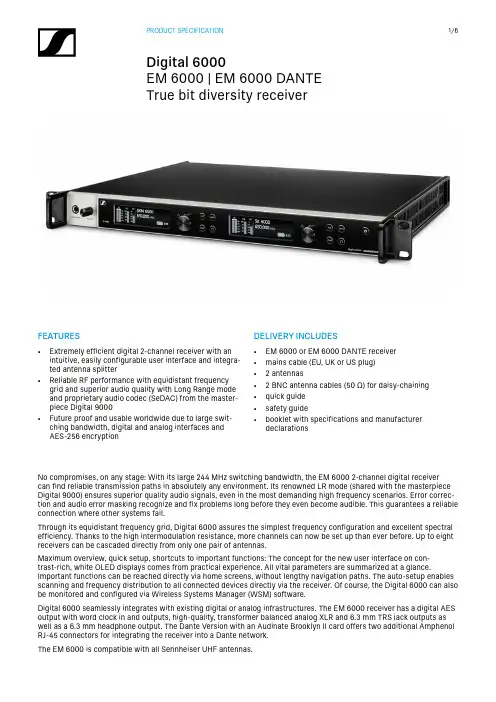
True bit diversity receiverFEATURES• Extremely efficient digital 2-channel receiver with anintuitive, easily configurable user interface and integra-ted antenna splitter • Reliable RF performance with equidistant frequencygrid and superior audio quality with Long Range mode and proprietary audio codec (SeDAC) from the master-piece Digital 9000• Future proof and usable worldwide due to large swit-ching bandwidth, digital and analog interfaces and AES-256 encryptionDELIVERY INCLUDES• EM 6000 or EM 6000 DANTE receiver • mains cable (EU, UK or US plug)• 2 antennas• 2 BNC antenna cables (50 Ω) for daisy-chaining • quick guide • safety guide• booklet with specifications and manufacturerdeclarationsNo compromises, on any stage: With its large 244 MHz switching bandwidth, the EM 6000 2-channel digital receiver can find reliable transmission paths in absolutely any environment. Its renowned LR mode (shared with the masterpiece Digital 9000) ensures superior quality audio signals, even in the most demanding high frequency scenarios. Error correc-tion and audio error masking recognize and fix problems long before they even become audible. This guarantees a reliable connection where other systems fail.Through its equidistant frequency grid, Digital 6000 assures the simplest frequency configuration and excellent spectral efficiency. Thanks to the high intermodulation resistance, more channels can now be set up than ever before. Up to eight receivers can be cascaded directly from only one pair of antennas.Maximum overview, quick setup, shortcuts to important functions: The concept for the new user interface on con-trast-rich, white OLED displays comes from practical experience. All vital parameters are summarized at a glance.Important functions can be reached directly via home screens, without lengthy navigation paths. The auto-setup enables scanning and frequency distribution to all connected devices directly via the receiver. Of course, the Digital 6000 can also be monitored and configured via Wireless Systems Manager (WSM) software.Digital 6000 seamlessly integrates with existing digital or analog infrastructures. The EM 6000 receiver has a digital AES output with word clock in and outputs, high-quality, transformer balanced analog XLR and 6.3 mm TRS jack outputs as well as a 6.3 mm headphone output. The Dante Version with an Audinate Brooklyn II card offers two additional Amphenol RJ-45 connectors for integrating the receiver into a Dante network.The EM 6000 is compatible with all Sennheiser UHF antennas.True bit diversity receiverFrequency range470 to 714 MHzTransmission scheme Digital modulationLong Range ModeMin. frequency spacing forequidistant grid: 325 kHzAudio codec SeDAC (Sennheiser DigitalAudio Codec)Dynamic range111 dB (A) typ.Encryption AES 256Latency Analog audio out: 3 msDigital audio out: 3 ms(AES/EBU)Total harmonic distortion(THD)< 0.03 % (at 1 kHz)Temperature Operation: −10 °C to +50 °CStorage: −25 °C to +70 °CRelative air humidity Operation:max. 85 % at 40 °C(non-condensing)Storage:max. 90 % at 40 °C(non-condensing)Dripping and splashing liquids The product must not be exposed to dripping and splashing (IP2X)Receiving channels2Receiver principle Double superheterodyne Diversity True Bit Diversity Sensitivity−100 dBm typicalImage rejection> 100 dB typical Blocking> 80 dB typicalAudio frequency response30 Hz to 20 kHz (1.5 dB) Analog audio outputs XLR-3 and 6.3 mm jackper channel (transformerbalanced),−10 dBu to +18 dBu in stepsof 1 dB (2 kΩ)Digital audio outputs AES3-2003, XLR-3:48 kHz, 96 kHz, 24 bitDante™, RJ-45(only EM 6000 DANTE):48 kHz, 96 kHz, 24 bitCan be externally synchro-nized using WCLK loop-th-rough with BNC sockets Headphone output 6.3 mm jack,2 × 100 mW at 32 ΩAntenna inputs 2 × BNC (50 Ω)Daisy chain outputs 2 × BNC (50 Ω)0 dB +/− 0.5 dB amplifi-cation relative to antennainputsDaisy-chained receivers(RF)Max. 8 EM 6000 unitsBooster supply voltage12 V DC, max. 200 mA eachvia antenna sockets, shortcircuit proofWord clock input BNC, 75 ΩWord clock output BNC, 75 ΩWord clock sampling rates48 kHz, 96 kHzNetwork IEEE 802.3-2002(10/100 Mbit/s), shieldedRJ-45 connectionDante™(only EM 6000 DANTE)IEEE 802.3 (1000 Mbit/s),2 × shielded RJ-45 connec-tionPower supply100 to 240 V AC, 50/60 Hz Power consumption Max. 35 WPower plug3-pin, protection class I asper IEC/EN 60320-1 Dimensions (H × W × Dwith mounting elements)44 × 483 × 373 mm Weight Approx. 5.2 kgSPECIFICATIONSTrue bit diversity receiverCONNECTIONS EM 6000EM 6000 DANTEPRODUCT VARIANTSEM 6000 EU Art. no. 506657EM 6000 UK Art. no. 506658EM 6000 US Art. no. 506659EM 6000 DANTE EU Art. no. 508475EM 6000 DANTE UK Art. no. 508476EM 6000 DANTE USArt. no. 508477ACCESSORIESA 2003 UHF passive directional antennaArt. no. 003658AD 3700active directional an-tennaArt. no. 502197A 1031-U passive omni-directional antennaArt. no. 004645A 3700active omni-directional antennaArt. no. 502195AB 3700broadband antenna boosterArt. no. 502196A 5000-CPpassive circular polariz-ation antennaArt. no. 500887COMPATIBLE WITH• SKM 9000 in Long Range mode • SK 9000 in Long Range modeSYSTEM COMPONENTS• SKM 6000• SK 6000• SK 6212• L 6000• L 60True bit diversity receiverDIMENSIONSBNC Buchse RCA-Buchse Dual BNC BuchseTrue bit diversity receiver DIMENSIONS14True bit diversity receiverSennheiser electronic GmbH & Co. KG · Am Labor 1 · 30900 Wedemark · Germany · ARCHITECT‘S SPECIFICATIONThe rack-mountable 2-channel receiver shall be for use with two companion handheld or bodypack transmitters as part of a digital wireless RF transmission system.The true bit diversity receiver shall operate in the UHF frequency range between 470 and 714 MHz. The receiver shall be usable with active and passive wide range UHF antennas for the entire supported RF spectrum. RF selection filters shall be integrated into the receiver´s frontend.The receiver shall feature 6 fixed frequency banks with up to 66 compatible frequency presets each and 6 user bankswith up to 66 user programmable frequencies each. The receiver shall feature an automatic frequency setup function with spectrum scan functionality in order to establish an equidistant frequency grid. Additionally, the receiver shall feature a frequency bank/channel setup to all associated receivers connected to the same network range.The receiver shall be menu-driven with an OLED display for each of the 2 channels showing the current frequency or channel name, metering of RF level, a link quality indicator (LQI), metering of AF level, AES 256 encryption status, com-mand mode status and battery status of the associated transmitter. An additional red LED shall indicate warning messa-ges.The following settings shall be configurable by function buttons and an encoder for each channel in the menu: frequency, channel name, AES 256 encryption, command mode, AF output, test tone, user bank frequencies, wordclock settings, network settings, integrated antenna booster settings, display brightness, auto setup settings for automatic frequency setup.Some parameters of the associated transmitters such as frequency, channel name, gain, low cut, auto lock and cable emulation shall be adjustable in the receiver and synchronizable to the associated transmitter via an integrated infrared interface.The receiver shall feature a command mode which allows the audio signal to be routed to a different audio output if a transmitter with a command button is used.The receiver shall provide a walktest mode for monitoring the RF, LQI and AF signal status in the location over time.The receiver shall feature one XLR-3 and one 6.3 mm jack analog audio output for each of the 2 channels with a maximum output of +18 dBu. The analog outputs shall be transformer balanced. The receiver shall also feature an AES3-2003 XLR-3 digital audio output. A headphone output with headphone volume control shall be provided and shall utilize a 6.3 mm stereo jack socket. The headphone output shall support audio monitoring of both channels indepently or a mix of both channels.The receiver shall have an Ethernet port (RJ-45) for remote network-based monitoring and control using the Sennheiser Wireless System Manager software, Wavetool software as well as Yamaha CL/QL and Soundcraft Vi000 consoles.Two BNC-type input sockets (50 Ω each) shall be provided for connecting the antennas. An integrated antenna splitter with two BNC outputs (50 Ω each) shall be capable of daisy-chaining up to eight receivers. Booster supply voltage shall be 12 V DC, max. 200 mA each via the antenna sockets and shall be switchable.The receiver principle shall be double superheterodyne. Sensitivity shall be -100 dBm (typical). Image rejection shall be > 100 dB (typical) and blocking shall be > 80 dB (typical). The audio frequency response shall be 30 Hz to 20 kHz (1.5 dB). The audio output level shall be adjustable in steps of 1 dB between -10 dBu and +18 dBu. Latency for both analog and digital audio out shall be 3 ms. Total harmonic distortion (THD) shall be < 0.03 % at 1 kHz.Supported wordclock sampling rates shall be 48 kHz and 96 kHz internal and external. The sampling rate of the digital audio outputs shall be adjustable between 48 kHz or 96 kHz at 24 bit.For secure transmission the receiver shall feature AES 256 encryption.The receiver shall operate on 100 to 240 V power supplied via a mains cable with EU, UK or US plug. Power consumption shall be max. 35 W. The receiver shall have a rugged metal housing; dimensions shall be approximately 44 x 483 x 373 mm (1.75" x 19" x 14.69"). Weight shall be approximately 5200 grams (11 lbs 7 oz). Operating temperature shall range from −10 °C to +50 °C (+14 °F to +122 °F).The receiver shall be the Sennheiser EM 6000.The Dante™ variant of the receiver shall feature an additional Dante™ interface with an Audinate Brooklyn Card with two RJ-45 sockets (primary and secondary) to support 2 independent redundant Dante™ networks and a daisy-chain mode. The sampling rate shall be adjustable between 48 kHz or 96 kHz internal or external at 24 bit. The Dante RJ-45 network sockets shall be lockable Amphenol™ sockets.The Dante™ variant of the receiver shall be the Sennheiser EM 6000 DANTE.。
位置传感器: 德国IFM电感式传感器,德国IFM电容式传感器,德国IFM磁性传感器,德国IFM 气缸传感器,德国IFM叉式和角型光电传感器,德国IFM激光传感器,德国IFM测距传感器,德国IFM光纤传感器和放大器,德国IFM针对特定应用的光电传感器,德国IFM阀门及阀门执行器反馈系统,德国IFM开关放大器,易福门德国IFM电感式传感器,德国IFM漫反射传感器, 德国IFM镜面反射传感器,德国IFM光电传感器,德国IFM流量传感器现货特卖,IFM传感器价格好货期短,金牌代理德国IFM,ifm电容式传感器质量,ifm电容式传感器价格,ifm电容式传感器报价,专注代理十年IFM传感器,特惠IFM全系列产品,IFM官网,特价代理IFM全系列产品,德国IFM中国一级代理商现货供应德国IFM传感器,正品销售IFM全系列产品,中国一级代理德国IFM,德国IFM上海总代理,德国易福门IFM官网,100%原装正品德国IFM传感器,IFM传感器,IFM上海总代理,易福门IFM—中国,100%正品销售德国IFM产品,德国IFM全系列产品,德国IFM官网,德国IFM中国总经销,德国IFM中国总代理,德国IFM上海总代理,德国IFM苏州总代理,德国IFM华东办事处,德国IFM华东总代理,德国IFM常州总代理,德国IFM天津总代理,德国IFM北京总代理,德国IFM济南总代理,德国IFM南昌总代理,德国IFM江西总代理,德国IFM赣州总代理,德国IFM深圳总代理,德国IFM无锡总代理,德国IFM昆山总代理德国IFM中国,德国IFM上海办事处,德国IFM苏州办事处,德国IFM常州总代理,德国IFM天津办事处,德国IFM北京办事处,德国IFM济南办事处,德国IFM南昌办事处,德国IFM江西办事处,德国IFM杭州办事处,德国IFM深圳办事处,德国IFM无锡办事处,德国IFM昆山办事处100%正品销售德国易福门产品,德国易福门全系列产品,德国易福门官网,德国易福门中国总经销,德国易福门中国总代理,德国易福门上海总代理,德国易福门苏州总代理,德国易福门华东办事处,德国易福门华东总代理,德国易福门常州总代理,德国易福门天津总代理,德国易福门北京总代理,德国易福门济南总代理,德国易福门南昌总代理,德国易福门江西总代理,德国易福门大连总代理,德国易福门深圳总代理,德国易福门无锡总代理,德国易福门昆山总代理,德国易福门沈阳总代理,IFM销量第一传感器德国IFM对射式传感器,原厂拿货德国IFM叉式传感器,IFM角型光电传感器,IFM全系列产品,德国IFM授权代理,IFM单圈实心轴编码器,常期优势供应IFM压力传感器,德国IFM原厂拿货,现货特价IFM传感器,德国IFM易福门全系列产品厂家直销,德国IFM易福门全国总代理经销,德国IFM (易福门)一级经销代理,低价销售德国IFM易福门全系列产品,德国IFM(易福门)全系列产品,IFM增量型编码器,易福门空心轴编码器,IFM传感器说明书,IFM上海代理德国易福门中国总代理,德国易福门天津总代理,德国易福门上海办事处,德国易福门苏州办事处,德国易福门济南办事处,供应易福门全系列产品,IFM价格,德国IFM报价单,德国IFM 详细资料,厂家直供IFM传感器,易福门在线报价德国易福门对射式传感器,德国易福门电感式传感器,德国易福门电容式传感器,德国易福门磁性传感器,德国易福门气缸传感器,德国易福门叉式光电传感器,德国易福门角型光电传感器,德国易福门激光传感器,易福门测距传感器,德国易福门光纤传感器,德国易福门放大器,德国易福门针对特定应用的光电传感器,德国易福门阀门及阀门执行器反馈系统,德国易福门开关放大器,德国易福门电感式传感器,德国易福门漫反射传感器, 德国易福门镜面反射传感器,德国易福门光电传感器,德国易福门对射式传感器,现货供应德国IFM转速传感,特约IFM传感器-代理商,IFM现货特价,IFM气缸传感器工作原理,IFM编码器B6001工作原理现货供应德国易福门传感器,正品销售易福门全系列产品,中国一级代理德国易福门,德国易福门上海总代理,德国易福门官网,100%原装正品德国易福门传感器,易福门传感器,易福门上海总代理,易福门—中国,易福门华东办事处,德国IFM全系列产品原厂拿货,美国威斯特优势供应IFM压力传感器,德国IFM大量库存,德国易福门特约代理,哪里能买到正品的IFM传感器/开关,哪里有卖正品IFM编码器,IFM实心轴编码器德国易福门是我司优势品牌,我司常年优价供应德国IFM电感式传感器,德国IFM电容传感器,德国IFM 磁性传感器,德国IFM气缸传感器,德国IFM红外线传感器,德国IFM叉式传感器,德国IFM角型光电传感器,德国IFM激光传感器,德国IFM光纤传感器,德国IFM编码器,德国IFM转速传感器,德国IFM倾角传感器等IFM全系列产品。
外型尺寸-30G M s e r i e s超声波UC500-30GM-IUR2-V15Notes注意D a t e o f i s s u e 07/19/2002型号此超声波传感器有4个温度/设定插头,可连接到4个不同位置。
功能见下表插头位置 含义A1 设定开关点A2 设定开关点E2/E3 切换: 2个独立开关点/窗口功能T 温度补偿设定功能说明:开关点1或2的设定-断开电源-拨下设定插头-恢复电源(复位)-将目标放在需要的开关点上-在位置1和2插上和拨去设定插头。
开关点A1或A2就设好了。
注意;移去温度/设定插头,目标位置值就被采用了。
-设定过程由LED指示。
绿色LED闪烁,目标被检测到;目标没有检测到,红色LED闪烁 -连接设定插头到位置T。
设定过程完成,传感器在正常方式下工作。
开关功能的设定-断电-拨下设定插头-恢复电源(复位)-连接设定插头到E2/E3。
可设定三种不同的工作方式:-开关点方式,LEDA1闪烁-窗口方式,LEDA2闪烁-滞后方式,LEDA1和A2闪烁连接设定插头到位置下。
设定过程完成,传感器在正常方式下工作。
注意:若温度插头在5分钟内没有插入,传感器将回到正常模式(带最新的存储值),不带温度补偿同步此传感器有一个同步输入,用于抑制相互间的干扰。
若不使用这个同步输入端,窜肝气将通过内部激发的时钟频率来工作。
使用方波电压可能同步。
下降沿使超声波脉冲传输。
≥1s的低电平或同步输入端开路使传感器在正常方式下工作。
高电平>1s使传感器在备用方式下工作(绿色LED指示)。
最新状态下输出中断。
同步不可在设定过程中实施,反之亦然。
多路工作方式可行1.把同步输入端相连,可使2到5个传感器同步。
传感器传输超声波脉冲2.多个传感器可以由同一个同步信号来控制。
传感器被置于同步方式3.同步脉冲循环发送到单个传感器。
传感器以同步方式工作。
4.同步输入端的高电平使传感器失能传感器同步时,响应时间增加,因为同步使得检测循环时间加长-初始设置值A1: 近点A2: 标称距离LED显示UC500-30GM-IUR2-V15D a t e o f i s s u e 07/19/2002超声波传感器用软件 ULTRA 2001设定参数----------------连接PC)开关1和2上升输出/下降输出/零线工作方式音速温度漂移(对固有的传感器温升可考虑温度补偿)育区扩展(用于抑制育区回声)检测范围减小(用于远方回声的抑制)检测循环时间声音功率(破裂干扰)灵敏度回声丢失时传感器的动作出错时传感器的动作允许的检测周期数的平均值参数设定选择,RS232或人工设定。
外型尺寸-30G M s e r i e s超声波UC4000-30GM-IUR2-V15Notes注意D a t e o f i s s u e 07/19/2002型号此超声波传感器有4个温度/设定插头,可连接到4个不同位置。
功能见下表UC4000-30GM-E7R2-V15设定功能说明:开关点1或2的设定-断开电源-拨下设定插头-恢复电源(复位)-将目标放在需要的开关点上-在位置1和2插上和拨去设定插头。
开关点1或A2就设好了。
注意;移去温度/设定插头,目标位置值就被采用了。
-设定过程由LED指示。
绿色LED闪烁,目标被检测到;目标没有检测到,红色LED闪烁 -连接设定插头到位置T。
设定过程完成,传感器在正常方式下工作。
开关功能的设定-断电-拨下设定插头-恢复电源(复位)-连接设定插头到E2/E3。
可设定三种不同的工作方式:-开关点方式,LEDA1闪烁-窗口方式,LEDA2闪烁-滞后方式,LEDA1和A2闪烁连接设定插头到位置下。
设定过程完成,传感器在正常方式下工作。
注意:若温度插头在5分钟内没有插入,传感器将回到正常模式(带最新的存储值),不带温度补偿同步此传感器有一个同步输入,用于抑制相互间的干扰。
若不使用这个同步输入端,传感器将通过内部激发的时钟频率来工作。
使用方波电压可能同步。
下降沿使超声波脉冲传输。
≥1s的低电平或同步输入端开路使传感器在正常方式下工作。
高电平>1s使传感器在备用方式下工作(绿色LED指示)。
最新状态下输出中断。
同步不可在设定过程中实施,反之亦然。
多路工作方式可行1.把同步输入端相连,可使2到5个传感器同步。
传感器传输超声波脉冲2.多个传感器可以由同一个同步信号来控制。
传感器被置于同步方式3.同步脉冲循环发送到单个传感器。
传感器以同步方式工作。
4.同步输入端的高电平使传感器失能。
传感器同步时,响应时间增加,因为同步使得检测循环时间加长-初始设置值A1: 近点A2: 标称距离LED显示D a t e o f i s s u e 07/19/2002超声波传感器用软件 ULTRA 2001设定参数--------------连接PC)开关1和2上升/下降输出/零线工作方式音速温度漂移(对固有的传感器温升可考虑温度补偿)育区扩展(用于抑制育区回声)检测范围减小(用于远方回声的抑制)检测循环时间声音功率(破裂干扰)灵敏度回声丢失时传感器的动作出错时传感器的动作允许的检测周期数的平均值参数设定选择,RS232或人工设定。