Fluorescence or Phosphorescence - UThink Blogs at the 荧光或磷光- uthink博客在
- 格式:ppt
- 大小:2.74 MB
- 文档页数:6
中英互译水势(water potential渗透势(osmotic potential溶质势(solute potential蒸腾作用(transpiration)光合作用(photosynthesis原初反应(primary reaction)光合单位(photosynthetic unit)光补偿点(Light Compensation Point,LCP)光抑制(photoinhibition)CO2补偿点(CO2 compensa-tion point)末端氧化酶(terminal oxidase)长日植物(long-day plant,LDP)短日植物(short-day plant,SDP)日中性植物(day-neutral plant,DNP)植物生理学(plant physiology)质膜(plasma membrane)内膜系统(endomembrane system)内质网(endoplasmic reticulum)高尔基体(Golgi body)液泡(vacuole)过氧化物酶体(peroxisome)乙醛酸循环体(glyoxysome)细胞核(cell nucleus)线粒体(mitochondrion)质体(plastid)白色体(leucoplast)叶绿体(chloroplast)有色体(chromoplast)细胞质基质(cytoplasmic matrix)细胞骨架(cytoskeleton)胞间连丝(plasmodesma)共质体(symplast)质外体(apoplast)扩散作用(diffusion)渗透作用(osmosis)压力势(pressure potential衬质势(matrix potential水孔蛋白(aquaporin)蒸腾速率(transpiration rate)蒸腾比率(transpiration ratio)蒸腾系数(transpiration coefficient)内聚力学说(cohesion theory)矿质营养(mineral nutrition)矿质元素(mineral element)灰分元素(ash element)必需元素(essential element)溶液培养法(solution culture method)水培法(hydroponics)砂基培养法(sand culture method) 有益元素(benefieial element)。


New External Triggering OptionsInstructions for Spectrometers withFirmware Version 3.0 and Above OverviewOcean Optics spectrometers with FPGA Firmware Version 3.0 and above provide several methods of acquiring data (see table below). In the Normal/Free-Run mode, the spectrometer is “free running.” That is, the spectrometer is continuously scanning, acquiring, and transferring data to your computer, according to parameters set in the software. In this mode, however, there is no way to synchronize the scanning, acquisition, and transfer of data with an external event. However, trigger pulses for synchronizing an external event with the spectrometer are available.To synchronize data acquisition with external events, other modes of acquiring data are available. Each mode involves connecting an external triggering device to the spectrometer and then applying an external trigger to the spectrometer before the software receives the data. The length of the integration time and the source for the integration clock depend upon the mode chosen. All other acquisition parameters are set in the software.Also see the External Triggering Options Instructions for triggering information for other Ocean Optics spectrometers with firmware versions below 3.0.Triggering Mode Description Use This Trigger Mode When You …Normal/Free-Run Spectrometer acquires spectracontinuously.No synchronization to other events is neededSoftware Integration time is set in the software.Software receives a trigger event andtransmits spectra obtained in the dataacquisition cycle in which the triggeroccurred.Are using a continuous illumination source, and the light intensity is constant before, during, and after the trigger.Need to set the integration time in the software.External Triggering Options Instructions for FW3.0and AboveTriggering Mode Description Use This Trigger Mode When You …External Hardware Level Trigger Integration time set via software on achip in spectrometer. The spectrometerwaits for a sharp rise in voltage on thetrigger input pin, and then acquiresspectra until the voltage is removed.Need a continuous acquisitionwhenever a certain condition is met,such as:-when reacting to a sample beingpresent or-when a sample reaches a specificstate that you want to measureExternal Synchronous Trigger Spectrometer acquires data from anexternal trigger event (such as a pushbutton) until the next time the trigger isactivated, at which time thespectrometer ceases spectralacquisition and begins a newacquisition. Integration time cannot beset, since the trigger can fire at randomintervals.Must synchronize your scans to anexternal clock sourceAre using a lock-in amplifierAre using a chopperExternal Hardware Edge Trigger Integration time set via software on achip in spectrometer. The spectrometerwaits for a sharp rise in voltage on thetrigger input pin, and then acquiresspectra.This trigger acquires onespectrum each time that there is asharp rising edge (if an acquisition isnot already in progress).Are using a pulsed excitation source orlight source in your experiment (suchas a laser or flash lamp)Are doing LIF (fluorescence withpulsed excitation) or phosphorescenceexperimentsNeed to synchronize an acquisitionwith an external eventSetting Up for External Triggering IMPORTANT:Voltage RegulationThe maximum recommended voltage on the Triggering Pin is 5.5 V.If your triggering device exceeds this voltage, you must regulate or condition the signal (via transistor buffering, transformer isolation or opto-isolation, for example) or isolate the signal from the spectrometer.NoteTo use one of the External Triggering options, you must know the specifications andlimitations of the triggering device. The design of the triggering device may prevent youfrom using one of the external triggering modes as it is described in these pages.External Triggering Instructions for FW3.0and Above Pinout Diagrams for Ocean Optics SpectrometersHR4000,HR2000+,Maya2000Pro and Maya-LSL and Maya-LSL,NIRQuest,QE65000, QE65Pro, and QE ProFor external triggering,supply a line from Pin 10 of the multi-pin connector on the spectrometer to your triggering device.Be sure to also use the Ground Pin when triggering. See the appropriate spectrometer Data Sheet to locate the ground pin(s).Pin-out Diagram of 30-pin Connector on HR4000,HR2000+,NIRQuest,Maya2000Pro and Maya-LSL,QE65000, QE65Pro,and QE Pro SpectrometersUSB2000+ and USB4000For external triggering, supply a line from Pin 7 of the multi-pin connector on the spectrometer to your triggering device. Be sure to also use Ground Pin 6 when triggering.Pin-out Diagram of 22-pin Connector on USB2000+, Flame-S,USB4000, and Flame-T SpectrometersFlame-S,Flame-T, and Flame-NIRFor external triggering, supply a line from Pin 2of the multi-pin connector on the spectrometer to your triggering device. Be sure to also use Ground Pin 1when triggering.When facing the 40-pin Accessory Connector on the front of the vertical wall of the Flame, pinnumber 1 is on the right.Pin-out Diagram of40-pin Connector on Flame-S,Flame-T and Flame-NIR SpectrometersExternal Triggering Options Instructions for FW3.0and AboveSetting Integration Time in SoftwareSoftware,External Hardware Level Trigger and External Hardware Edge Trigger modes can have the integration time set via OceanView or SpectraSuite.Set Integration Time with OceanViewUse the Main Controls of the Set Acquisition Parameters in OceanView to select the trigger mode and to set the integration time.The Automatic button in the Integration Time control box automatically adjusts the spectrometer’s integration time to bring the highest point of the signal to 85% of full saturation value. This value is represented by the horizontal blue line on the preview graph.External Triggering Instructions for FW3.0and AboveThe integration time may also be set manually by using the numeric spinner control and the drop-down units menu.Note that the Nonlinearity Correction control is grayed out until the Electric Dark control is enabled.Also note that once a triggering mode for the spectrometer has been set, the device will wait for an external trigger before continuing. It will appear as though the spectrometer has locked up and no further data acquisitions will occur until the External Trigger pin on the device receives a signal.External Triggering Options Instructions for FW3.0and AboveSet Integration Time with SpectraSuiteUse the External Trigger selection box on the Trigger toolbar to set the trigger mode of the spectrometer to Software.NoteOnce you select an external trigger mode, your computer will appear unresponsive. Thisis normal, as the computer is waiting for a trigger. You must apply one more trigger tothe spectrometer after selecting a new trigger mode.External Triggering vs. Triggering an External EventThere could be some confusion between the concepts of External Triggering and triggering an external event. The following sections explain each of these concepts:∙External Triggering–An event outside the sampling system (such as a push button, lever activation, or laser pulse) triggers the voltage level on the spectrometer’s trigger pin and instructs the spectrometer to begin spectra acquisition.∙Triggering an External Event–When triggering an external event, the spectrometer instructs an external device (typically a lamp such as the PX-2 or the LS-450) to illuminate immediately prior to spectral acquisition.Trigger Mode DescriptionsThe following sections specify the Trigger modes for Ocean Optics spectrometers with firmware versions 3.0 and above and associated timing sequences.For the Maya2000Pro and Maya-LSL,NIRQuest,Flame-NIR,HR2000+,USB2000+, Flame-S,HR4000, USB4000,and Flame-T,the timing sequences specified are for the trigger mechanism interacting with a single-depth FIFO.The hardware implementing these Trigger modes may enhance the capability and performance by implementing buffering schemes using larger or multiple FIFOs.For the QE65000,the timing sequences specified are for the trigger mechanism interacting with a triple-depth FIFO. The hardware implementing these Trigger modes enhances the capability and performance by implementing a buffering scheme using multiple FIFOs.In addition, the QE Pro has a 15,698-deep buffer.External Triggering Instructions for FW3.0and Above Normal ModeIn the Normal (Free-run) mode, the spectrometer will acquire one spectrum for each “get spectrum”command issued from the host software.The integration time for each spectrum is pre-programmed prior to the host issuing its “get spectrum” command.The spectrometer waits in a repetitive idling loop until it receives the next “get spectrum” command.Once the command is received, the spectrometer exposes the detector for the pre-programmed integration time, and its resulting spectrum is written to an internal FIFO.The spectrometer signals the host that a spectrum is ready, and the host reads out the new spectrum.Upon reading out the new spectrum, the host immediately commands the spectrometer to acquire the next spectrum.In this process, the spectrometer is responding “on-demand”to the host’s “get spectrum” commands.The spectrometer waits in an idle state between each spectrum and the next “get spectrum” command.The spectrometer does not pre-fetch any spectra in anticipation of the next “get spectrum” command.For the QE65000spectrometer, integrations are continuously performed with the most recent three spectra available to the host software. The QE65000 has an internal FIFO which can hold up to three contiguous spectra.To maximize throughput, the QE6500 is constantly pre-fetching spectra back-to-back, independent of the host’s “get spectrum” command.However, if the host fails to issue a “get spectrum” command by the time the third spectrum is pre-fetched, the QE65000 clears its FIFO and starts 3 new acquisitions.In this process, the QE65000 is pre-fetching back-to-back spectra in anticipation of the host’s “get spectrum” command.For the QE Pro, there are no idle cycles that drop new spectra; all new spectra are stored in the buffer and are available to the user (if buffering is enabled). If the buffer limit is exceeded (15,698), the oldest spectrum is automatically discarded to make room for the new spectrum. The user can clear the buffer at any time.External Triggering Options Instructions for FW3.0and AboveNormal Mode Timing SequenceSoftware Trigger ModeIn this level-triggered mode, the spectrometer is “free running,” just as it is in the Normal mode. The spectrometer is continually scanning and collecting data. With each trigger, the data collected up to the trigger event is transferred to the software. If you continuously apply triggers (for example, by holding down the button on via an external switch), this mode is equivalent to operating in the Normal mode.In the Software Trigger mode, you set the integration time (as well as all other acquisition parameters) in the software.The source for the integration clock comes from the A/D converter.External Triggering Instructions for FW3.0and Above If the software trigger is asserted during integration cycle n, the photons from this integration period will be readout and digitized at the start of integration cycle n+1External Software Triggering–Trigger TimingExternal Synchronous Trigger ModeIn the External Synchronous Trigger Mode, two external triggers are required to complete a data acquisition. The first rising edge starts the integration period and the second rising edge stops the integration while starting the next integration. Thus the integration time is the period between the two external trigger pulses. After the each integration period, the spectra is retrieved and written to the FIFO in the FPGA.For the Maya2000Pro and Maya-LSL, HR2000+,USB2000+,Flame-S and Flame-NIR,as in all nonbuffered modes, no further integrations are possible until the software has read the entire contents of the FIFO.For the QE65000, three spectrum buffers provide software with the most recent spectral acquisitions.External Triggering Options Instructions for FW3.0and AboveExternal Synchronous Trigger Mode Timing SequenceExternal Hardware Level Trigger ModeIn the External Hardware Level Trigger mode, a rising edge detected by the FPGA from the External Trigger input starts the Integration Cycle specified through the software interface. After the Integration Cycle completes, the spectrum is retrieved and written to the FIFO in the FPGA. As long as the trigger level remains active in a logic one state, continuous acquisitions will occur with the following exception. Each subsequent acquisition must wait until a minimum CCD Reset Cycle completes. This Reset Cycle insures that the CCD performance uniform on a scan-to-scan basis. The time duration for this reset cycle is relative to the Integration Cycle time and will change if the integration period is changed. So the timing sequence is Trigger, Trigger Delay,Integration Cycle, Read/Write Cycle, Reset Cycle, Idle Cycle(s), and Integration Cycle (if trigger is still high). The Idle Cycle will on last 2µs if the trigger remains high and the FIFO is empty and a spectrum request is active, otherwise the Idle Cycle will continue until all 3 conditions are satisfied.For the Maya2000Pro and Maya-LSL, HR2000+,USB2000+,Flame-S and Flame-NIR, as in all nonbuffered modes, no integrations are possible until the software has read the entire contents of the FIFO.External Hardware Level Trigger Mode Timing SequenceFor the QE65000, three spectrum buffers provide software with the most recent spectral acquisitions.QE65000 Hardware Level Trigger ModeQE Pro Hardware Level Trigger ModeExternal Hardware Edge Trigger ModeIn the External Hardware Edge Trigger mode, a rising edge detected by the FPGA from the External Trigger input starts the Integration Cycle specified through the software interface. After the Integration Cycle completes, the spectrum is retrieved and written to the FIFO in the FPGA followed by a CCD Reset Cycle. Only one acquisition will be performed for each External Trigger pulse, no matter what thepulse’s duration is. The Reset Cycle insures that the CCD performance uniform on a scan-to-scan basis. The time duration for this reset cycle is relative to the Integration Cycle time and will change if the integration period is changed. So the timing sequence is Trigger, Trigger Delay, Integration Cycle, Read/Write Cycle, Reset Cycle, and Idle Cycle(s). The Idle Cycle will until the next trigger occurs.NoteFor the QE Pro, jitter between external edge trigger and start of column binning (ortrigger delay) is 40ns.Maya2000Pro and Maya-LSL,and QE65000 Hardware Edge Trigger Mode Time TableQE Pro Hardware Edge Trigger Mode Time TableHR2000+,USB2000+and Flame-S Hardware Edge Trigger Mode Time TableNIRQuest Hardware Trigger Mode Time TableHR4000,USB4000and Flame-T TimetablesIt is important to note that the trigger timing in the USB4000and Flame-T will vary depending upon the integration time.This is further detailed in the Time Tables that appear below. These tables reveal that the trigger timing will be different for the following ranges of integration times:∙< 3.8 ms∙ 3.8 ms to 199 ms∙200 ms to 2097 ms∙2097 msUSB Command Description for TriggeringThe USB command Set Trigger Mode sets the spectrometer trigger to one of the trigger mode states as shown below.HR2000+,USB2000+and Flame-S Set Trigger ModeData Value = 0→Normal (Free running) ModeData Value = 1→Software Trigger ModeData Value = 2→External Hardware Level Trigger ModeData Value = 3→External Synchronization Trigger ModeData Value = 4→External Hardware Edge Trigger ModeHR4000,USB4000and Flame-T Set Trigger ModeData Value = 0→Normal (Free running) ModeData Value = 1→Software Trigger ModeData Value = 2→External Hardware Level Trigger ModeData Value = 3→Normal(Shutter)ModeData Value = 4→External Hardware Edge Trigger ModeMaya2000Pro and Maya-LSL,QE65000, QE65 Pro, and QE Pro Set Trigger ModeData Value = 0→Normal (Free running) ModeData Value = 1→External Hardware Level Trigger ModeData Value = 2→External Synchronous Trigger Mode*Data Value = 3→External Hardware Edge Trigger Mode*Not yet implemented on the QE ProNIRQuest Set Trigger ModeData Value = 0→Normal (Free running) ModeData Value = 3→External Hardware Edge Trigger Mode。
荧光磷光tadf发光原理英文回答:The principle of fluorescence phosphorescence in TADF (Thermally Activated Delayed Fluorescence) can be explained as follows. TADF is a process in which the excitons (electron-hole pairs) generated in the organic molecules can undergo intersystem crossing (ISC) from the excited singlet state to the excited triplet state, followed by reverse ISC from the excited triplet state back to the excited singlet state. This process is known as reverse intersystem crossing (RISC). During RISC, the excitons can emit light, resulting in fluorescence or phosphorescence.In TADF materials, the energy gap between the singlet and triplet states is small, allowing for efficient ISC and RISC processes. This means that both singlet and triplet excitons can contribute to the emission of light. When an electric current is applied to a TADF material, electrons and holes are injected into the organic molecules, creatingexcitons. These excitons can undergo ISC and RISC processes, leading to the emission of light.One example of a TADF material is TADF emitter TADF-1, which consists of a donor and an acceptor unit connected by a conjugated bridge. When an electric current is applied to TADF-1, the donor unit donates an electron to the acceptor unit, creating an exciton. This exciton can undergo ISC and RISC processes, resulting in the emission of light. The emission color of TADF-1 can be tuned by modifying thedonor and acceptor units, allowing for the development of TADF materials with various emission colors.中文回答:荧光磷光TADF(热激活延迟荧光)的发光原理可以如下解释。
Biologists and physicians have al-ways searched for answers to thefollowing questions: How is the cell structured? Which cell mod-ules are responsible for which processes? How does the individ-ual cell function? How does the cell act in tissues?I n addition to many other ex-amination techniques, fluores-cence microscopy also provides answers to these questions. Fluo-rescence micrographs help re-searchers understand the structure of cells and their components, as well as the mechanisms withinthem. Fluorescence microscopy has long been one of the most important research tools in medicine and natural sciences,allowing more than just the examination of bacteria and viruses. Today, fluorescence forms the basis of many modern tech-niques in the life sciences.finally emit light of less energy and greater wavelength in the visible range when these electrons return to their previous, lower energy level.Luminescence and illumination are closely related: if the body is no longer illuminated, luminescence will disappear.Autofluorescence, primary and secondary fluorescence are variations of fluorescence. Fluorescence is some-times called photoluminescence.When a chemical reaction releases energy, it can also appear as light: in other words, chemoluminescence or chemical light. One familiar example of this is luminol, used by police departments, that lights up bluish green in the presence of blood. One particular type of chemolumi-nescence is bioluminescence, i.e. the ability of living creatures to produce light either on their own or with the help of symbionts.The Fluorescence PhenomenonLuminescence effects Luminescence (Latin word lumen =light) is a body’s ability to emit light when illuminated by a light source.Scientifically speaking, luminescence is the optical radiation of a physicalsystem produced during the transfer from an excited condition to a basic condition. Light emission is triggered by excitation in the UV , IR or visible light range.Phosphorescence and fluorescence Luminescence can be divided into two phenomenons: phosphorescence and fluorescence. In phosphores-cence, the body continues to light up even if it is no longer illuminated.Fluorescence is the ability of certain chemical substances to absorb short-wave light energy and reflect itseemingly simultaneously as long-wave light: for example, invisible,short-wave, high-energy daylight portions (e.g. UV light or X-rays), are absorbed first and then stored for a more or less long period of time; they then excite electrons for quantum leaps into a higher energy level andMany centuries later,Nicolás Monardes (1493-1588) observed luminescence for the first time in 1565 in an extract of Lignum nephriticum – a drug recommended at the time for the treatment of kidney diseases.Nicolás Monardes1493–1588Brief history of fluorescenceThe fluorescence phenomenon has been observed for thousands of years.However,it was not until today that we understand this pheno-menon and have been able to control and make use of the process.Phenomenons now known as fluorescence and phosphorescence were mentioned in Chinese books as far back as 1500 BC.Fig.1:Glial cell culture from the optic nerves (visual nerve)of a goldfish.Astrocytes were identified with a GFAP (glial fibrillary acidic protein) antiserum,an intermediate filament (green fluorescence).Oligodendrocytes express myelin-specific gangliosides on their surface that have been detected using a monoclonal antibody (red fluorescence).All cell nuclei are stained blue with DAPI.Micrograph:Martin Bastmeyer,Friedrich Schiller University,JenaIn his book …Ars MagnaLucis et Umbrae“,Athanasius Kircher(1602-1680) describes theeffect of a wood extract(lignum nephriticum) inwater and discussed theapplication of fireflies toilluminate houses. Athanasius KircherWhile experimentingwith silver chlorideat Jena University,Johann Wilhelm Ritter(1776-1810) discoveredthe ultraviolet end of thespectrum in 1801. Johann Wilhelm Ritter1602–1680 1776–1810In his “Theory of Colors”,Johann Wolfgang vonGoethe(1749-1832) alsodescribes fluorescent lightphenomenons.He asks hisreaders to “… dip a freshpiece of horse chestnutbark into a glass of water,which will then turnsky-blue immediately”.Johann Wolfgang v.Goethe1749–1832Sir David Brewster(1781-1868),the inventorof the kaleidoscope,described the red radiationof chlorophyll in 1833.Sir David BrewsterIn 1845,Sir John FrederickWilliam Herschel(1792-1871) discoveredthe phenomenon offluorescence in a quininesolution.Sir John Frederick William HerschelIn 1842,Sir GeorgeGabriel Stokes(1819-1903) describedthe luminescence observedin the fluorspar mineral(calcium fluoride) asfluorescence.Sir George Gabriel Stokes1781–1868 1792–1871 1819–1903returns to its original condition after the emission of light, enabling it to be reused again and again. The green luminescence of these jellyfish is generated by the combination of GFP (Green Fluorescent Protein) and aequorine.GFP variants modified by genetic engineering play a major role in cur-rent research in the natural sciences.As early as 1994, it was demonstrat-ed that GFP can be coupled with other proteins without loss of the flu-orescent features of GFP or the func-tions of the GFP-coupled proteins.Further types of luminescence in-clude electro and carthodolumines-cence. In electroluminescence, excita-tion is achieved through an electrical current, such as in the case of light-emitting diodes. In carthodolumines-cence, excitation is achieved through electron bombardment (example: TV screen).Bioluminescence therefore is a special type of luminescence that performs various functions in flora and fauna,including the luring of prey and also of partners. Further functions are warning, threat and communication signals. Nature also uses biolumines-cence for deterrence and camou-flage. Familiar phenomena include marine luminescence, caused by plankton, such as dinoflagellate noc-tiluca, that react to current changes by emitting light. Fireflies, krills and fish use bioluminescence for various functions. Bioluminescent bacteria are also known for this phenomenon.The Vibrio Fischeri bacterium repro-duces on dead saltwater fish, for example, and its growth can be easily observed on a dead salted herring. In bioluminescence, energy is frequently released in the form of light resulting from the oxidation of luciferin with the help of the luciferase enzyme.The aequorea victoria jellyfish and the renilla reniformis coral produce light slightly differently, namely by using photoproteins. Aequorea victo-ria uses aequorine, a Ca 2+ dependent primary photoprotein. Unlike lu-ciferin, it is not chemically transferred in the course of the reaction, butIn 1935,Alexander Jablonski (1898-1980)presented his diagram to explain fluorescence: a fluorochrome features different energy states,the so-called singlets (S0,S1,S2...).Alexander Jablonski Beginning in 1950,Albert Hewett Coons (1912-1978) and Melvin Kaplan developed the immunofluorescence technique that led to sensational results in cell research,an area of natural sciences.Albert Hewett Coons1898–1980In 1911,Max Haitinger (1868-1946),who is considered the founder of modern fluorescence microscopy and thefluorochroming technique,coined the term “fluorochrome”.Max Haitinger 1868–19461912–1978Fig.2:Cerebellum (rat),super-oxide dismutase (blue),Glial Fibrillary Acidic Protein (yellow)Institute for Medical Neurobiology,Magdeburg,Germany.Fluorescence microscopy – the key technology formany modern methods in the life sciences enabling life functions to be made visible. Increasingly differentiated fluorescence applications have enabled science to track down molecular interactions within cells image by image.Carl Zeiss has pioneered the development of fluores-cence microscopy right from the start. Today, new optical systems visualize weakest fluorescence signals,separate overlapping fluorescence spectra anddocument dynamic life processes at highest recording speed. Complex applications are made accessible to a wide variety of users.The growing demands made on optical systems can be easily implemented with LSM 5 LIVE and Axio Imager . Our focus on key techniques for the research of life has now been given a name: FluoresScience from Carl Zeiss.FluoresScience from Carl Zeiss specialThe development team around Dr. Ulrich Simon,Dr. Bernhard Zimmermann and Ralf Wolleschensky from theMicroscopy Group was nominated for the 2004 German Future Prize for the market-ready development of the LSM 510 META laser scanning microscope.Nominated for German Future PrizeThe German Future Prize, awarded by the German Federal President,is an annual award honoring outstanding innovations in tech-nology, engineering and natural sciences within Germany. It is not possible to apply for the prize. The right to make recommenda-tions for the German Future Prize lies with leading German establish-ments in science and industry. The “LSM 510 META ” project was nominated by the Federal Associa-tion of German Industry (BDI).1904August Köhler published his study reports about the ultraviolet microscope.1913Beginning in 1913,H.Lehmann and Stanislaus von Prowazek promoted development of the first apparatus allowing visualization and also measurement of fluorescence.The first optical instrument – still called a luminescencemicroscope – was introduced by Carl Zeiss as early as 1913.1935The Ellinger-Hirt luminescence microscope was mainly used for intravital microscopy.1982The development of the first laser scanning microscope by Carl Zeiss laid the founda-tions for today's ultramodern three-dimensional reconstruction of cell structures in fluorescence microscopy.detailsFluorescence-optical instruments from CaFig.3:Endothelial cells,nucleus (blue:DAPI),F-actin (green:BODIPY FL),Mitochondria(red:mitotracker red).Fluorescence is the basis of many modern methods in the life sciences.Fluorescent proteins in particular have become the key method in the search for the secrets of life in the early 1990s. Today, an increasing number of new, more differentiated fluorescence applications such as FRET, FRAP or FlAsH allow tracking of molecular interrelations inside the cell.In the beginning, fluorescence mi-croscopy was performed as transmit-ted-light fluorescence microscopy.The far more efficient epi-fluores-cence microscopy then replaced the transmitted-light technique almost completely.The modern reflected-light tech-nique has one major optical benefit:the objective also acts as a con-denser, thus ensuring optimum align-ment of the light beam.www.zeiss.dewww.deutscher-zukunftspreis.de www2.uni-jena.de/biologie/zoologie2001The LSM 510 META ideally implements the confocal principle like no other system.It permits the recording of multifluorescence without making any concessions on resolution and efficiency.1986Carl Zeiss made another major contribution to the further development of fluorescence microscopy with its microscopes in the Axio series featuring ICS optics.2004One hundred years after Köhler’s invention of the “ultraviolet microscope”,Carl Zeiss set a further milestone in fluorescence microscopy with the new Axio Imager microscope.2002In traditional microscopy,ApoTome enables very fast,high-quality optical sections through fluorescence-labeled specimens – e.g.for the 3-dimensional display of nerve cells.rl Zeiss。
荧光fluorescence发光luminescence纳米颗粒nanoparticle稀土离子rare earth ions稀土发光luminescence of rare earth ions激光光谱laser spectroscopy表面增强荧光surface enhanced fluorescence 等离激元光子学plasmonicsWikipedia光,称为诱发荧光。
2原理光照射到某些原子时,光的能量使原子核周围的一些电子由原来的轨道跃迁到了能量更高的轨道,即从基态跃迁到第一激发单线态或第二激发单线态等。
第一激发单线态或第二激发单线态等是不稳定的,所以会恢复基态,当电子由第一激发单线态恢复到基态时,能量会以光的形式释放,所以产生荧光。
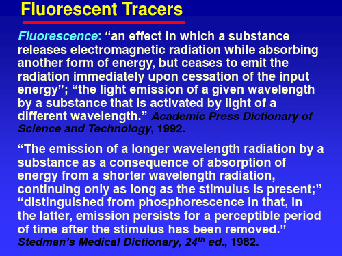
荧光是物质吸收光照或者其他电磁辐射后发出的光。
大多数情况下,发光波长比吸收波长较长,能量更低。
但是,当吸收强度较大时,可能发生双光子吸收现象,导致辐射波长短于吸收波长的情况发生。
当辐射波长与吸收波长相等时,既是共振荧光。
常见的例子是物质吸收紫外光,发出可见波段荧光,我们生活中的荧光灯就是这个原理,涂覆在灯管的荧光粉吸收灯管中汞蒸气发射的紫外光,而后由荧光粉发出可见光,实现人眼可见。
3相关参数(1)激发光谱:激发光谱是指不同波长的激发引起发射出某一波长荧光的相对效率。
(2)发射光谱:又为荧光光谱,是分子吸收辐射后再发射的结果。
(3)荧光强度:荧光强度与该种物质的荧光量子产率、消光系数以及含量等因素有关。
(4)荧光量子产率Q:量子产率表示物质将吸收的光能转化为荧光的本领,是荧光物质发出光子数与吸收光子数的比值。
(5)斯托克司(stokes)位移:斯托克司位移为最大荧光波长与最大激发波长之差。
(6)荧光寿命:当一束光激发荧光物质时,荧光物质的分子吸收能量后从基态跃迁到某一激发态,再以辐射的形式发出荧光回到基态,激发停止时,分子的荧光强度降低到激发时最大强度的1/e时所需的时间为荧光寿命。