科显电子大屏幕手册
- 格式:doc
- 大小:1.32 MB
- 文档页数:9

Electric Motorized Projection Screen VMAX 2 SeriesUser’s GuideCaution: The screen’s Black Top Drop is already set to its maximum drop distance. There is NO extra Black Top Drop in the roller. Please be aware of this as it will void your warranty with Elite Screens. Unapproved changes or modifications (except for cutting the power cord for hardwire installations) to this unit are prohibited and will void your warranty. For more information, please contact our Technical SupportDepartment at (877) 511-1211 Ext. 604.•Please retain this user’s guide for future reference.•To avoid damaging the unit, do not use with any unauthorized accessories not recommended by the manufacturer.•Handle the unit carefully during transportation to avoid any damages.•To ensure safe and reliable operation, direct connection to a properly grounded power source is advised.•The power outlet supplying power to the unit should be close to the unit and easily accessible.•Do not install the unit on uneven or inclined surfaces.•Do not put heavy objects on the power cord and position it properly to avoid creating a trip obstacle.•Never overload the power cord to prevent an electric shock or fire due to a loose contact or a short circuit.•There are not user serviceable parts in this unit. Do not attempt to disassemble this unit by yourself. No one except authorized technicians can open and make repairs to thisunit.•Make sure the power source this unit is connected to has a continuous power flow.•If there is need to use an extension cord, make sure the cord has an equal rating as the appliance to avoid overheat.•Do not handle the power plug when your hands are wet or your feet are in contact with water.Do not use this unit under the following circumstances.•Disconnect the power cord under the conditions of heavy rain, wind, thunder or lightning.•Avoid direct Sunshine, rain shower and moisture.•Keep away from fire sources and high temperature to prevent this device from overheating.•Cut off the power supply first before transportation or maintenance.•Fully disconnect from the power supply when the unit is not in use for a long period of time, as should be done with any other electric household appliance.•To avoid possible injury and/or an electric shock, do not attempt to use the screen if there is obvious damage or if there are any evident broken parts.Due to various installation environments, the instructions provided in this user’s guide are for reference only. Please consult a professional installation company for further installation and safety advice. The installer must insure that proper mounting hardware is used to provide adequate strength suitable for the installation. Elite Screens is not liable for any faulty installations.The Screen’s Top Black Drop is already set to its maximum drop distance. There is NO extra top black drop in the roller. Please be aware of this as it will void the limitation of your warranty.Individual modifications to this product are prohibited and will void the warranty with the manufacturer. Please contact Elite Screens Customer Service for any questions.NOTE:This equipment has been tested and found to comply with the limits for a Class B digital device, pursuant to Part 15 of the FCC Rules.These limits are designed to provide reasonable protection against harmful interference in a residential installation. This equipment generates and can radiate radio frequency energy and, if not installed and used in accordance with the instructions, may cause harmful interference to radio communications.However, there is no guarantee that the interference will not occur on a particular installation. If this equipment causes harmful interference to radio or television reception, which can be determined by turning the equipment off and on, the user is encouraged to try to correct the interference by one or more of the following measures.Reorient or relocate the receiving antenna of the device which may be casing the interference.Increase the separation between the screen and the device’s receiver.Connect the equipment into a different power outlet other than the device.1.Carefully unpack the screen.2.Always handle the screen in a leveled position on a clean surface.3.In order to protect the screen from exposure to stains, keep the screen out of contact withforeign particles such as dust, sawdust, and/or liquids.Regardless of the mounting method, the screen should be securely supported so that the vibration or pulling on the viewing surface will not cause the casing to become loose or fall. The installer must insure that the fasteners used are of adequate strength and suitable for the installation location.Red+Green-A. B. C. D.Infrared Remote Radio Frequency 12 Volt Trigger 3 Way Wall Switch D. E. F.Infrared Eye Receiver AAA Batteries Bubble LevelUP1. 5-12V Trigger: The built-in 5-12V trigger input allows your screen to synchronize its drop & rise with the projector’s power cycle. The screen deploys when the projector powers up and will retract when the projector powers down. The 5-12 volt adaptor connects to your projector’s triggeroutput via a separate cable that may or may not be provided by the manufacturer of the projector. The trigger feature will not work without an output cable from the projector, but it can be tested by connecting the Red (+) and Green (-) cable to a 9-volt battery. 3-prong power cable2. 3 -Way Wall Switch: The 3-way wall switch is a wall mount control box with an up/stop/down button and plugs directly into the screen’s RJ-45 input.3. IR “Eye” Receiver: The IR “Eye” Receiver plugs directly into the screen’s RJ-45 input to present a low profile line-of-sight control option for your IR remote control even ina recessed ceiling installation.Please consult a professional installer. Elite Screens is not liable for any faulty installations.1.Select the installation location for your screen. Ensure that it is within reasonable proximity from yourpower source.2.For best support of your screen, it is ideal to secure your screen into the studs of your house’s internalframework. If studs are not available, use hollow anchors for mounting your wall screws into drywall. If you’re installing in a concrete structure, use concrete bolts to secure your screen.Always consult a professional installer or hardware professional to ensure that the proper screws and/or hardware are being used.3.Ensure that both brackets are in perfect level alignment with one another. Use wall/c e iling wood screwsto secure to the wood studs. Use hollow anchors if mounting in drywall.4.The screen casing is designed to accept the wall screws directly. If not using the Optional L-Brackets/accessories.aspx, be sure to position the washer between the head of the wall-screw and the anchor slots on the screen’s casing.ing a tape measure, mark the keyholes that are located at the back of the screen’s casing end cap.6.After marking the area and predrilled hole, insert the screw and have at least 1/8” from the wall to mountthe screen. (See example in Figure 1.)7.Figure 2 will show you an optional installation using chains (not included).For additional information, please contact Elite Screens at ****************************1.If your screen does not move, please check the power supply. The screen will understandablynot move without power.2.Make sure the power cord is firmly plugged to the power outlet.3.Make sure that all cable connections are secure.4.If the screen works well with the line switch but not with the remote control, please make surethe remote controls have fresh batteries. Change the batteries every 6 months to ensure proper operation of the remotes.1.Q: Why does my screen no longer function?A: Make sure your wall plug has power and that the screen is properly plugged. The fuse on the screen will also need to be checked. Please contact **************************** for the location. The tubular motor in this screen is equipped with a thermal relay. This feature will automatically shut off the screen in the event of the motor becoming too hot. This will prevent the motor from overheating. If you should experience this, please let the screen’s temperature decrease for 10-15 min. before usage.2.Q: How is the screen material cleaned?A: The screen material can be cleaned with mild soap and water.3.Q: What type of batteries do the remote controls require?A: The IR and RF remote controls use AAA alkaline batteries.4.Q: Can you manually pull down the screen?A: No, manually pulling down the screen will damage the electronic motor rolling system and void your warranty.5.Q:How could I setup my Screens IR receiver to work with my learning remote control systemDo you have any IR codes I can use to achieve this?A: Our IR remote controls have been evaluated and entered in to the databases of someUniversal remote control manufacturers. Please contact the manufacturer of your remote to inquire about your remotes ability to function with ours. If they have not evaluated our remote control then the following list of Binary codes will be used for most remote setups.For Spectrum, VMAX2 (Plus), Home2 and CineTension 2 SeriesUp: 1111 0000 0001Stop: 1111 0000 0010Down: 1111 0000 0100*Measurement dimensions are intended as a reference only and subject to change without notice. Note: Data Error may be ±1"•Two (2) Year parts and labor warranty from defects in workmanship from purchase date as follows (except for refurbished units as specified below).•Three (3) Year parts and labor warranty from defects in workmanship for GEMR (Government, Educational, Military, & Religious) purchases of new product only.•Refurbished Units carry a 90-DAY parts and labor warranty.•Each party will be responsible for one way shipping during the warranty period.•A RMA (Return Merchandise Authorization) number must be issued in order to process a replacement or to authorize a return for warranty repair. Elite Screens will, at its sole option replace or repair the defective unit with a replacement *(see exceptions below) after thedefective unit or parts have been received. Once the product is received, Elite Screens will send out a replacement *unit to the customer by ground service (subject to inventory availability). •Do Not Return Any Unauthorized Items to Elite Screens, as they will be refused and returned at your expense. The RMA Number must be included on the outside label of your shipping box. Our warehouse is not authorized to accept returns without an RMA number on the shipping label.•RMA Numbers are valid for 45 days from the date issued.•Missing Parts must be reported within 7 days of receipt. If reported after 7 days, the customer will be responsible for shipping and handling fees. If reported after 30 days of receipt, the customer will be responsible for cost of parts and shipping & handling fees.*A New or refurbished replacement will be send out to the customer depending on the type of purchase (new or refurbished) and based on stock availability.North America only U.S. and CanadaFor Warranty and Service requests, please submit an RMA/Service Form at:/warrantysupportformPlease visit this link for full Warranty information:/warrantyFor Customer Service and Technical questions, please contact Elite Screens at:Telephone: (877) 511-1211 ************************Fax: (562) 926-8433 ****************************REMEMBER TO REGISTER YOUR PRODUCT AT:US & Canada Tech Support & Warranty ClaimPlease contact us at ************************ or call +1 877-511-1211 #3 or fax +1-562-926-8433 Europe Tech Support & Warranty ClaimPlease contact us at *********************** or call +49-(0) 40-30392958Asia Tech Support & Warranty ClaimPlease contact us at ************************.cn or call +86-(0) 755-8461-7989Taiwan Tech Support & Warranty ClaimPlease contact us at ************************.tw or call +866+2+8990-1999America:Europe:Elite Screens Inc Elite Screens Europe16410 Manning Way Lübecker Straße 1Cerritos, CA 90703 USA 22087 Hamburg, GermanyTel: +1-877-511-1211 Tel: +49-4030392494Fax: +1-562-926-8433 Fax: +49-40-49219200***************************************** www.elitescreens.euAsia: Elite Screens France S.A.SElite Screens China Corp.11, Allée William PennLongxi Duimianling Industry Zone 92150 Surenes, France Longcheng Longgang District, Tel: +33-1-45064735ShenZhen GuangDong,China Fax: +33-1-45064735Tel:+86-(0)755-8461-7989 ************************Fax:+86-(0)755-8461-7669 /fr*********************.cnJapan:Taiwan: Elite Screens Japan Corp.Elite Screens Taiwan Corp. 467-2-606 Tsuruma, Machida-shi, 4F., No. 42-1 Wuguan Rd. Wugu Township Taipei Tokyo, 194-0004 JapanCounty 248, Taiwan (Wugu Industrial Park) Tel: 0120-07-0008Taiwan (R.O.C) Fax: + 81(0)42-706-9130Tel:+886+2+8990-1999 ********************Fax:+886+2+8990+1366 www.elitescreens.jp*********************.twLatin America Contact:************************East Asia Contact:************************India Contact:***************************。

DLP大屏幕系统操作手册1.1 DLP大屏幕系统组成矿业DLP大屏幕投影拼接显示系统包括拼接单元组合墙体、图像拼接控制器、大屏控制控制管理软件、矩阵切换器、接口设备、专用线缆等,由以下部分组成:◆拼接单元组合墙体:本大屏幕投影显示墙由6套50″拼接单元组成,组合方式为2×3(行 列);✧50单元屏幕尺寸:1026mm宽×762 mm高x 680 mm 厚;✧整屏显示面积为:(1026 mm×3)×( 762mm×2)= 3078mm宽×1524mm高✧整屏分辨率为:(1024×3)×(768×2)=3072×1536✧单元底座高度:实际高度根据用户现场确定;✧核心部件采用美国TI公司最新发布的12°偏转角0.7″ LVDS DMD,DDP3020F投影芯片,物理分辨率达1024×768。
✧采用复合玻璃幕,采用纯无机材料,整墙屏幕平整度≤0.3mm,增益度为3.7,水平视角为>160度,垂直视角为>80度无缝拼接组合方式,物理拼缝小于0.5mm。
附上大屏系统尺寸图如下:50 2x3 大屏系统尺寸图◆多屏全硬件拼接图像处理器-拼接控制器是一款性能强大的高端图像处理设备,能够在多个显示终端上同时显示多个动态画面,主要用于大屏幕拼接显示系统,是系统的核心显示控制设备。
拼接控制器采用目前最新的计算机集成技术、网络技术,并具有特有的独立PCI64/66总线传输技术,系统资源占用少,稳定可靠。
控制器集超宽带视频信号采集、实时高分辨率数字图像处理、二维高阶数字滤波等高端图像处理技术于一身,具有强大的处理能力。
控制器采用多总线并行处理机制,能从根本上保证对所有输入视频进行全实时处理,图像没有延迟,无丢桢现象。
拼接控制器支持多种视频输入模式,包括复合视频(DVD 或摄像头信号),计算机视频(电脑信号VGA 或DVI )等。

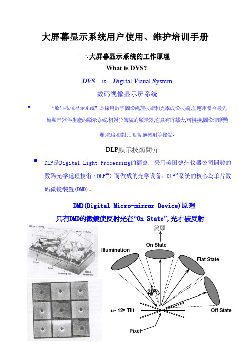
大屏幕显示系统用户使用、维护培训手册一.大屏幕显示系统的工作原理DVS is D igital V isual S ystem数码视像显示屏系统• “数码视像显示系统” 是採用數字圖像處理技術和光學成像技術,並應用當今最先進顯示器件生產的顯示系統.相對於傳統的顯示器,它具有屏幕大,可拼接,圖像清晰艷麗,亮度和對比度高,無輻射等優點.What is DVS?DLP顯示技術簡介•DLP是Digital Light Processing的簡寫. 采用美国德州仪器公司開發的数码光学處理技術(DLP TM)而做成的光学设备。
DLP TM系统的核心為单片数码微镜装置(DMD)。
DMD(Digital Micro-mirror Device)原理On State鏡頭只有DMD的微鏡使反射光在“On State”,光才被反射120W 燈泡和橢圓反射鏡 色輪=50mm 紫外線-紅外線 濾鏡透鏡1透鏡 2 反射鏡透鏡 3稜鏡DMD 芯片 發射鏡DLP 光學引擎 VW-50A 燈泡 色輪 透鏡 稜鏡 DMDProjection Lens DLP(Digital Light Processing)光學引擎成像原理透鏡 紫外線-紅外線濾鏡光机的构成主要部件及位置电源模组AC BOX 控制模组DLP光机点灯模组输入连接端口透镜散热DMD板光機灯泡组件二.中达电通DVS產品中达DVS的产品特性:採用美国德州仪器公司的数码光学处理(DLP TM)技术可轻松接入多路信号以VW-50A為例,它可直接輸入1路C-VIDEO信號,2路RGB信號,並可實現多台DVS信號串聯,由於閉路電視信號為已調制信號,需增加解調器方可接入内部圖像分离器很容易用内部分离器将圖像分割。
各单元间数码信号的转移和交换本系统的投影单元有数码的输入/输出接口(RS232和DVI)。
输入到第一个单元中的数码信号可利用传输线分发到其它的有传输线相连的单元中。
可利用设备间数码信号的转换功能实现用一个信号转换器控制和接拨多路信号。

PXL2430MW LED Touch Monitor 触控屏液晶显示器USER'S GUIDE使用手册ContentOperation Instructions (1)Unpacking Instructions (2)Safety Precautions (2)Front View of the Product (3)Rear View of the Product (4)Quick Installation (5)Basic Operation and Calibration/Reset Instructions (6)Advanced Operation—OSD Menu (8)Supporting Timing Modes (11)Technical Information (12)Wall-Mount Installation Instructions (13)Troubleshooting (14)Product Registration and Technical Support (15)Thank you for purchasing the PX L2430MW multi-touch LED monitor. Please read this guide thoroughly before installation.FCC RADIO FREQUENCY INTERFERENCE STATEMENTWARNING: (FOR FCC CERTIFIED MODELS)This LED Monitor has been tested and found compliant with the limits for a Class B digital device, pursuant to part 15 of the FCC Rules. These limits are designed to provide proper protection against harmful interference to a residential installation. This Touchscreen LED Monitor generates, uses, and can radiate radio frequency energy. Harmful interference to radio communication may be the result if it‘s not properly installed and used. However, there is no guarantee that interference will not occur in a particular installation. If this Touchscreen LED Monitor does cause serious interference to radio or television reception, resetting may correct it. Moreover, users are encouraged to reduce interference by doing one or more of the following:Reorient or relocate the receiving antenna.Move the Touchscreen LED Monitor and the receiver further away from each other.Connect the Touchscreen LED Monitor into an outlet on a circuit different from that to which the receiver is connected.Consult your local dealer or a qualified technician.FCC Warning:To assure a continued FCC compliance, a user must use a grounded power supply cord and the provided shielded video interface cable with bonded ferrite cores. Also, any unauthorized changes or modifications to this Touchscreen LED Monitor would void the user‘s authority to operate this device.Note: If necessary, shielded interface cables and AC power cord must be used to meet the emission level limits.According to WEEE regulation, this Touchscreen LED Monitor can't be handled as normal trash in Europewhen it is out of usage. Please refer to the recycle information on Planar’s website to handle it.For more information on how to recycle your product, please visit /GREENMove the LED Monitor out of the package and take off the plastic bag and Polystyrene Foam. Pull the base from Parallel versus Panel to Vertical.Adjust the Panel between 0° leaning forward and 20° leaning backward.Safety PrecautionsFollow all warnings, precautions and maintenance as recommended in this user’s manual to maximize the life of your unit.Do:Turn off the product before cleaning.Touch screen surface may be cleaned using a soft clean cloth moistened with mild window glass commercial cleaners or 50/50 mixture of water and isopropyl alcohol.Use a soft cloth moistened with mild detergent to clean the display housing.Disconnect the power plug from AC outlet if the product is not going to be used for an extended period of time.Don’t:Do not touch the LED Display screen surface with sharp or hard objects.Do not use abrasive cleaners, waxes or solvents for your cleaning.Do not operate the product under the following conditions:o Extremely hot, cold or humid environment.o Areas susceptible to excessive dust and dirt.o Near any appliance generating a strong magnetic field.o In direct sunlight.If smoke, abnormal noise or odor emits from your Touchscreen LED Monitor, remove the power cord immediately and call your service center.Never remove the rear cover of your Touchscreen LED Monitor. The display unit inside contains high-voltage parts and may cause electric shock.Never try to repair your Touchscreen LED Monitor yourself. Always call your service center or a qualified technician to fix it.①②③④⑤⑥⑦①Touch Pen Slot②OSD Turn On/ Off③Volume Adjust/ Scroll Down/ Adjust Decrease④Preset Mode/ Scroll UP/ Adjust Increase⑤Input select/ Confirm Selection⑥LED Indicator⑦Power On/ OffEnglish⑧⑨⑩⑪⑫ ⑬⑭⑧Power Input⑨U SB - Type A to B⑩Headphone Jack⑪Audio Input⑫HDMI input (HDMI 19 pin)⑬DVI Input (DVI 24 pin)⑭VGA Input (D-Sub 15 pin)Quick Installation1. Connect either VGA, DVI or HDMI Video Source from the monitor to the computer. Makesure both monitor and computer are powered OFF.2. Connect the audio cable from audio output of computer to the audio input of the monitor.3. Connect the USB cable from the computer to the monitor.4. Connect power cord to a properly grounded AC outlet, and then to the monitor.5. Power-ON computer and then POWER-ON the monitor.6. Set the timing mode on your computer. Recommended resolution and refresh rate is 1920 x1080 @ 60Hz.Figure 1: PCAudio cableUSB 2.0 cableDVI cableVGA cable Power cableHDMI cable(not supplied)Basic Operation and Calibration/Reset InstructionsBefore using the Touchscreen LED Monitor:Connect external equipment properly.Insert the power plug, and the power LED indicator will light orange.Power On/OffTo turn the Touchscreen LED Monitor on/off:Press POWER button on the front. The power LED indicator light will be blue when the Touchscreen LED Monitor is on.Using the OSD MenuUse OSD menus to adjust settings by using the menu button on the front of the Touchscreen LED Monitor.Displays main menu1Exits from OSD menu2 Selects between VGA, DVI, HDMI or Auto modeSelect the desired item when in OSD menu▼When not in OSD menu, directly enters Volume adjustSelect the desired item when in OSD menu▲When not in OSD menu, directly enters Preset Mode▼ + ▲Recalls both Contrast and Brightness (when not in OSD menu)OSD Lock Out FunctionWhen Touchscreen LED Monitor is in normal mode, the “OSD Lock Out” function can be enabled. Option 1: OSD lock – all 4 buttons are locked except the “POWER” button.Press and hold the 1 button and the ▲ button for 10 seconds to lock the OSD buttons.The Touchscreen LED Monitor will show an “OSD Lock Out” message for 3 seconds and the message will disappear automatically.Repeat this step to unlock.Option 2: OSD & Power button lock – all 5 buttons including the “POWER” button are locked. Press and hold the 1 button and the ▼ button for 10 seconds to lock all 5 buttons.The Touchscreen LED Monitor will show a “Lock Out” message for 3 seconds and the message will disappear automatically.Repeat this step to unlock.PX2430MW Calibration/Reset Instructions:The PX2430MW is available with USB connection. It is Microsoft® Windows® 7 HID (Human Interface Device) compatible if you use the USB touch screen interface. No additional software driver is required. Calibration is a simple process and can be invoked by running Tablet PC Settings from Control Panel and clicking the Calibrate button.Click the Reset button to reset the touchscreen to the factory calibration settings. To reset the existing calibration data, click "Reset" in the Tablet PC Settings window.Advanced Operation—OSD MenuYou can use the OSD menu to adjust various settings for your Touchscreen LED Monitor. Press the1 button to display the OSD Menu, and use ▲▼to select the desired OSD menu.Short Cuts Function from the button(s)Auto Image Adjust: To auto adjust Horizontal Position, Vertical Position, Phase (Fine Tune) and Clock (H. Size) of the screen.Contrast: To adjust the foreground white level of screen image. ▲: increase contrast, ▼: decrease contrast.Brightness: To adjust the luminance of the video. ▲: increase brightness, ▼: decrease brightness.ECO Mode: Allows the user to turn the ECO On or Off. Contrast and Brightness adjustment disabled when ECO is active.Input Select: When Input Select is pressed, change Input signal to VGA, DVI, HDMI or Auto.Audio Adjust: To adjust the audio functions. Volume: To adjust the volume of speaker output. Mute: To turn the Mute ON/OFF.EnglishColor Adjust: To select the color for improving brightness and color saturationbetween 9300K, 6500K, 5400K, and User Color.9300K: Adds blue to screen image for cooler white.6500K: Adds red to screen image for warmer white and richer red.5400K: Adds green to screen image for a darker color.User Color:Individual adjustments for red (R), green (G), blue (B).1. Press button 2 to select the desired color.2. Press ▼ or ▲ button to adjust selected color.Information: To display the information, regarding the current input signal comingfrom the graphic card in your computer.Note: See your graphic card user guide for more information about changing the resolution and refresh rate.Manual Image Adjust: To manually adjust the Horizontal Size, H. /V. position, FineTune, Sharpness, Video Mode adjust and Preset Mode.Horizontal Size: To adjust the width of the screen image.▼: decrease the width of screen image, ▲: increase the width of screen image.H./V. Position: To adjust the horizontal and vertical position of the video.H. Position: ▲: move screen to the right, ▼: move screen to the left.V. Position:▲: move screen up, ▼: move screen down.Fine Tune: To adjust the delay time of data and clock.Press ▼ or ▲ to adjust to your preference.Sharpness: To adjust the clarity of a non-Full HD Resolution (1920x1080) signal with ▼or ▲ button.Video Mode Adjust:To select the video mode from Full Screen, Over Screen or Aspect Ratio.Full Screen: To select full-screen size image.Over Screen: To select over-screen size image.Warning: “Over Screen” may cause deviation in touch accuracy. If this occurs, we recommend using “Full screen”. Aspect Ratio: To select input timing image size.Preset Mode: Provides an optimum display environment depending on the contentsdisplayed. It contains 5 user-selectable presets.Standard is for general windows environment and monitor default setting.Game optimized for PC game environment.Cinema optimized for movie and video environment.Scenery optimized for displaying outdoor scenery images.Text optimized for text editing and viewing in a word processing environment.Setup Menu: To set up Language, OSD Position, OSD Time Out and OSD Background.Language Select:To allow users to choose from available languages.OSD Position: Press ▼ or ▲ button to select between horizontal and vertical OSD Position adjustment.H. Position: To horizontally adjust the OSD position.▲: move OSD to the right, ▼: move OSD to the left.V. Position: To vertically adjust the OSD position.▲: move OSD up, ▼: move OSD down.OSD Time Out: To automatically turn off On Screen Display (OSD) after a preset period of time.OSD Background: Allows the user to turn the OSD background On or Off.Memory Recall: To recall factory settings for Video & Audio controls.Press button 2 to select the Memory Recall menu option.Supporting Timing ModesSTANDARD RESOLUTIONVGA 720 x 400 @ 70HzVGA 640 x 480 @ 60HzMAC 640 x 480 @ 67HzVESA 640 x 480 @ 72HzVESA 640 x 480 @ 75HzVESA 800 x 600 @ 56HzVESA 800 x 600 @ 60HzVESA 800 x 600 @ 72HzVESA 800 x 600 @ 75HzMAC 832 x 624 @ 75HzVESA 1024 x 768 @ 60HzVESA 1024 x 768 @ 70HzVESA 1024 x 768 @ 75HzVESA 1280 x 960 @ 60HzVESA 1152 x 864 @ 75HzMAC 1152 x 870 @ 75HzVESA 1280 x 1024 @ 60HzVESA 1280 x 1024 @ 75HzVESA 1440 x 900 @ 60HzCVT 1400 x 1050 @ 60HzVESA 1600 x 1200 @ 60HzVESA 1680 x 1050 @ 60HzVESA 1920 x 1080 @ 60HzNote:1. DVI and HDMI supports 480i, 480p, 576i, 576p, 720p, 1080i, and 1080p.2. Simultaneously press 1 and 2 keys on monitor panel to switch between similar PC timings. Similar PC Timing on list below:• 720 x 400 @ 70Hz / 640 x 400 @ 70Hz • 1400 x 1050 @ 60Hz / 1680 x 1050 @ 60Hz Warning: Do not set the graphic card in your computer to exceed these maximum refresh rates. Doing so may result in permanent damage to your monitor.Technical InformationPanel 23.6” TFT (with LED backlight)Power Management On: 21 Watts (typical), 40 Watts (maximum)Standby Mode: < 0.5 WattOff: < 0.5 WattDisplayable Resolution Full HD 1920 x 1080 max. Vertical Frequency 60Hz max.Pixel Dimension 0.2715 x 0.2715 mmDisplay Color 16.7MTilt 4° (+3/-3) ~ 40° (+3/-3)Active Display Area 521.28 mm x 293.22 mmTemperature Operating: 0°C ~ +40°CStorage: -20°C ~ + 60°CCompliance FCC-B, CE, UL/cUL, CCCPower Input Voltage AC100-240 VSpeaker 2W x 2 (typical)Touchscreen Technology Touchscreen Interface Touch Method Supported O/S Optical TouchUSBFinger(s) and stylus input Microsoft Windows® 7Wall-Mount Installation InstructionsWall Mount Arm not includedTurn the power OFF then disconnect the cables from theTouchscreen LED Monitor before performing the procedurebelow.1. Lay the Touchscreen LED Monitor face down on a softsurface.2. Remove the two pieces of flake and Hinge Cover.3. Remove the two screws under the flake.4. Remove the stand.5. Follow instructions included with the Wall Mount kit.NOTE100mmx100mm VESA hole pattern (n=4), M4, pitch =0.7 mm100mm x 100mm ScrewMounting OptionsTroubleshootingNo powerMake sure A/C power cord is securely connected to the power adapter and the power supply is firmly connected to the Touchscreen LED Monitor.Plug another electrical device into the power outlet to verify that the outlet is supplying proper voltage.Make sure all signal cables are installed.Power on but no screen imageMake sure the video cable supplied with the Touchscreen LED Monitor is tightly secured to the video output port on back of the computer. If not, tightly secure it.Adjust brightness.Wrong or abnormal colorsIf any colors (red, green, blue) are missing, check the video cable to make sure it is securely connected. Loose or broken pins in the cable connector could cause an improper connection. Connect the Touchscreen LED Monitor to another computer.Product Registration and Technical SupportRegister Your Planar Products TodayThank you choosing Planar. To assure you receive all the benefits of your Planar product and services, register your Planar product today. Visit our website to register your product at/support/product_registration.htmlCables, Replacement Lamps, AccessoriesTo find cables, replacement lamps and accessories for your Planar projector, LCD monitor, touch screen or other Planar products visit our online store at or find other stores who carry Planar products at /howtobuyTechnical SupportVisit Planar at /support for product registration, operations manuals, touch screen drivers, warranty information and access to Planar's Technical Library for online troubleshooting. To speak with Planar Customer Support please have you model and serial number available and dial:Planar SupportTel: 1-866-PLANAR1 (866-752-6271) or +1 503-748-5799 outside the US.Hours: 24 hours a day, 7 days a week.Toll or long distance charges may apply.目录操作说明 (1)开箱说明 (2)安全预防措施 (2)产品前视图 (3)产品后视图 (4)快速安装 (5)基本操作和校准/复位说明 (6)高级操作—OSD菜单 (8)支持的时钟模式 (11)技术信息 (12)符合RoHS规范声明 (13)壁掛安裝說明 (14)故障排除 (15)产品注册和技术支持 (16)感谢您购买PXL2430MW多点触控屏液晶显示器。

VTRON操作维护手册大屏幕系统操作维护手册一┅┅┅┅┅┅┅┅┅┅┅┅┅┅┅┅┅┅┅┅┅┅┅┅┅┅┅┅开机二┅┅┅┅┅┅┅┅┅┅┅┅┅┅┅┅┅┅┅┅┅┅大屏幕管理软件操作三┅┅┅┅┅┅┅┅┅┅┅┅┅┅┅┅┅┅┅┅┅┅┅┅┅┅┅┅┅关机四┅┅┅┅┅┅┅┅┅┅┅┅┅┅┅┅┅┅┅┅┅┅┅┅┅┅故障及排除五┅┅┅┅┅┅┅┅┅┅┅┅┅┅┅┅┅┅┅┅┅┅┅┅┅┅日常维护请操作人员务必按照操作手册进行操作一、开机打开投影墙系统设备的所有电源开关→开D igicom图形处理器→在大屏幕控制机上用VWAS软件打开所有投影机。
(开机后等待4分钟左右投影墙会一起点亮)警告!!!在日常使用投影系统时,必须严格遵守系统使用注意事项,严禁在使用系统时突然断电,这样会引起系统的硬件和软件故障,严重的会损害系统设备!二、大屏幕管理软件操作1.软件的登陆步骤1.双击控制PC桌面的图标,就会弹出下图所示登录界面,在控制主机输入:“127.0.0.1”在用户名输入:“admin”;在密码输入: 111111 (6个1)按“确定”即可进入管理软件菜单。
如下图步骤2.右键点击模拟墙打开全部机芯即可开启投影机:接着调度(操作)员把临时PC接上会议室的网口,使用IE登录网址http://192.168.0.1:8080/VWAS5.5方式访问机房的大屏控制PC登录控制软件(确保控制电脑正常启动)。
2.信号的调用:当调用信号时,先要确定信号不能处于屏幕保护状态或在锁定状态,否则信号显示会出现不正常。
1.模式的调用如图所示,点击菜单中列表的“”就会弹出列表选中需要在大屏投影墙上显示的模式,双击鼠标“执行”,即可将对应的信号调用到大屏投影墙上显示。
2.视频信号源和RGB信号源的调用如图所示,点击菜单中列表的“”就会弹出列表把需要显示的视频信号用鼠标点击信号源按住Ctrl键在模拟屏上任意开处理器窗口输出,窗口大小和位置都可以用鼠标任意操作,可支持四路处理器VIDEO信号。
第一章.硬件设备简介1.1光源1.2接口接口输入端口的定义:输出通道0口可输出输入通道0或输入通道1信号,输出通道1口只能输出输入通道1信号.零通道输入端口的定义:1.3投影单元结构投影单元光学成像结构如下图2.1:反射镜成像幕投影机投影机 等效位置调整架调节螺母调整架调节螺母1) 投影机的光程决定图像的大小。
2) 投影机的投射角决定图像的方正形状。
3) 反射镜会影响上述因素。
第二章.控制软件的登陆步骤1.双击控制PC桌面的VWASExplorer图标,就会弹出下(图1)所示登录界面,(图1)在用户名输入:“ADMIN”;在密码输入:“111111”按“确定”即可进入管理软件菜单。
如下图(图2)(图2)步骤2.右击右面:(图4)步骤3.然后点击“打开所有机芯”即可点亮大屏幕【大约2分钟才亮起来】。
第三章.屏幕管理软件操作3.1 信号的调用:添加信号源点击信号源图标在信号源栏点击右键,选择菜单“添加信号源”,弹出如下图所示的信号源属性对话框。
在“名称”栏填入信号源的名字,在“输出”栏选择信号类型,信号的类型主要有:DRGB、ARGB、HDTV、SVIDEO、VIDEO、VLINK、音频、USER_CUSTOM、网络摄像头和DVS。
在“制式”栏选择信号的制式。
注意:某些类型的信号源可能没有制式,如DRGB。
若该信号源为可控制设备(如摄像头),选中复选框“可被外部程序控制”后,该信号源将可以被信号源控制程序控制。
用户还可以根据需要把一个或多个信号源放在一个“组”中。
“组”是指多个具有某种相同属性的信号源归类或集合。
通过使用组对不同类型的信号源进行分门别类地管理,可以让用户对信号源的操作和管理更加方便和快捷。
要添加组,可以在信号源栏上点击鼠标右键,在弹出的菜单中选择“添加组”,弹出组属性对话框。
3.2“模式”的使用:添加模式在“模式”栏点击右键,在弹出的左键菜单中选择“添加”项,将弹出如下图所示的模式属性对话框:首先填写的是该模式的名称,用于唯一识别该模式。
XK-2000 显示控制器使用手册本手册用于皮带机积算系统在安装和操作前请仔细阅读本手册并严格遵守设备操作规范南京文佳机电设备有限公司目录1、仪表概述 (2)2、技术规范 (5)3、仪表安装 (9)4、仪表接线 (10)5、操作运行 (20)6、系统校准 (31)7、控制调整 (49)8、参数说明 (50)第一章 XK-2000 概述1.1 功能简介:XK-2000 是以美国CYGNAL公司推出的高速、高性能混合信号处理单片计算机为核心而设计的多功能显示控制仪表,可以配合螺旋给料机、皮带机、称重料斗等使用。
仪表检测来自控制设备上的各种传感器信号,经过处理后在液晶显示器(4行汉字显示器)上显示、远程显示或通过数字通讯口传输给上位计算机显示,也可输出模拟量mA信号、继电器工作状态及报警输出信号。
XK-2000 仪表可应用于计量(控制)皮带机、固体流量计、质量流量计、质量加料机、称重加料机、减量喂料机。
XK-2000带两个隔离的RS485通讯接口:采用独立的多功能通信协议,并支持MODBUS 协议(附数据地址表)。
1.2 性能特点:●汉字显示菜单式用户操作界面:128×64点阵液晶显示器,四行汉字显示,六键操作系统。
●丰富的I/O资源:六个可编程开关量输入六个可编程继电器输出一路可用于PID控制的模拟量输入二路16位D/A(PWM)用于控制、流量、重量、速度的电流选择输出。
二路PID(0 ~ 20mA)电流控制输出●双路数字通讯接口:二个隔离的RS-485接口,用于:通讯口1、2,皆可选择专用独立的多功能通信协议及兼容的标准MODBUS 通讯协议。
通讯机器号:0 ~ 999数据传输率:0.3kbit/s ~ 115.2kbit/s。
多功能控制系统:软件集成多功能控制系统,可根据不同的工艺应用要求及称重方式选择不同的控制系统功能。
仪表控制具有手、自动选择。
自动清零(皮带秤自动整圈)、称重传感器满量程校准、流量校准功能。
L E D电子显示屏使用说明(精)LED FOR WINDOWS LED电子显示屏使用说明书北京金特维技术有限公司目录一、异步显示屏系统构成及安装 (2)二、软件的安装 (3)三、软件使用 (4)四、常见问题回答 (21)五、功能键说明......... ......... (22)一、异步显示屏系统构成及安装本系统由 LED 电子显示屏屏体、上位计算机、与计算机和控制器串口通讯线缆组成。
用户主要完成串口通讯线缆的制作。
线缆两头为两 DB9插孔头(如图 1.1所示 ,制作时 2对 2(主机信号接收可不连 , 3对 3(主机信号发送 , 5对 5(地线即可。
使用时,将线缆一头与计算机的一个串口相连,另一头与 LED 电子屏屏体相连。
DB9插头 DB9插孔图 1.11 2 3 4 5 5 4 3 2 19 8 7 6二、软件的安装1、 1 安装:对于像文件名后面的后缀是 .EXE 的软件直接将其复制到您的计算机中既可使用 , 如果是 setup 的安装文件 , 打开它 , 按照提示进行安装即可 .1、 2 卸载:如果您需要进行对此软件的卸载 , 只要找到此软件的卸载程序启动即可 . 如果是直接复制到您计算机的软件 , 它将不会有卸载程序 . 而您只要将其删除就可以啦 .1、 3 运行环境:◆操作系统中文 Windows95/98/ME(不建议使用 XP 系统◆最低配置CPU :奔腾 100MHz 以上内存:32M显卡:SVGA 16位色显示模式以上其它:RS232口◆建议配置CPU :奔腾 233MHz 或更高内存:64M 以上显卡:SVGA 24位色以上显示模式其它:RS232口 USB口 ( 需要 USB 对 COM 口的数据转换线三、软件的使用安装完成后,可在“开始”的“程序”菜单中找到 LED 电子显示屏目录,点击 LED 电子显示屏图标,启动软件,或通过直接在软件安装目录下,点击 LED.EXE 文件 ,来启动软件。
KXV2.01液晶图像拼接处理器
使
用
手
册
西安科显电子科技有限公司
前言
欢迎选用我公司产品,感谢您对我公司产品的支持!为了您能更好的使用本产品,使用前请仔细阅读本手册。
KXV2.01E是我公司大屏幕拼接产品家族中的一员,采用独特的嵌入式结构设计,可接受各种图像信号源输入,直接驱动全系列的大尺寸液晶屏(26 寸以上),并经分割、放大后,实时无失真地在各种大屏幕图像拼接墙体上显示。
处理过程完全硬件化, 不需要电脑和启动软件等操作,非常简便。
画面无延时,无拖尾现象, 自然流畅,画质细腻,最大支持10X10 的液晶屏拼接。
KXV2.01E液晶图像拼接处理器采用了运动侦测与补偿运算、内插运算、边缘平滑处理及杂波信号抑制等尖端处理技术,其3D 视频亮色分离电路单元, 3D 的逐行处理及帧频归一转化电路单元, 3D 数字信号降噪单元,可将普通PAL/NTSC 隔行扫描视频信号采集变为逐行扫描的,高画质、高分辨率的高清电视和计算机图像信号。
KXV2.01E液晶图像拼接处理器支持计算机图像信号输入及其显示,可实现最高达1920x1080 高分辨率WUXGA 输出,支持全系列的大尺寸液晶屏。
KXV2.01E系列处理器可以支持多路不同的视频源,同时显示在不同的屏幕上,使用者也可选择一路视频源或R GB 信号放大至原始图像
的N×M倍,在由显示单元组成的墙体上实现大屏幕拼接显示。
注意事项
○防止明火、高温和碰撞,请不要置于雨中或潮湿的地方。
○在调试和使用过程中,操作不当可能导致设备损坏。
○此设备可以连续使用。
○请勿在工作中频繁开关机,严禁敲打设备,以上行为都可能使设备损坏和加速设备老化。
○做到轻拿轻放。
安全使用说明
清洁——用软布擦拭清洁,勿使用酒精等化学溶液。
电压——该设备使用标准220V 交流市电。
能耗——本产品功耗根据所驱动液晶屏型号而定,总功率不大于300W。
长期不使用时请关闭电源,并拔掉插头。
环境——不要将本产品暴露在潮湿、雨、沙地或温度过高的地方存储和使用(加热设备或太阳光下)。
注意——该设备在工作时请将之置于通风干燥无强烈震动的地方。
常见故障处理
当本产品发生故障时,请立即切断电源,请不要试图拆开本机进行维修,可能会造成产品进一步损坏。
可按以下步骤进行排除,仍不能解决请与当地经销商或专业维修人员联系。
对用户自行维修过的产品,不在公司保修范围。
开始系统系统运行前,确保下列连线正常:
1:运行本软件的计算机的R S232 线已正确连接至控制器。
2:相关控制器的信号线,电源线已连接正确;系统运行步骤:
1:打开控制器电源,控制电源指示灯将亮起。
绿色,代表处于开机运行状态;橙色代表待机状态。
2. 运行本软件
找到控制软件文件夹,点击KX.exe 运行。
出现程序操作界面:
根据安装软件版本不同,上图示例中的界面及其内容可能会存在某些差别,可咨询我们的相关的售后服务人员。
上图中用红色字体标出操作界面的各部分的功能说明:
1. 菜单区:一些相关的菜单功能选择执行区。
2. 操作区:每一个方格单元代表对应的控制屏幕,可以通过鼠标或键盘的点选,拖拉的方式选择相应控制单元。
3.功能区:包含常用的功能按钮。
4.用户标题区:用户可根据本身要求,更改界面上的标题显示
5.信号切换区:用户可根据本身要求,可切换为用户所需信号
6.附加功能区:调用LED显示屏软件,远程控制,矩阵通道更改名称,外挂程序接口。
7.状态区:显示通讯口状态,操作权限状态,和当前的本机时间,日期等。
如何开始使用
1. 通讯设置单击主菜单中“系统配置”――》
“通讯配置”
选择正确的通讯端口号,系统才能正常工作。
可以设置打开程序时自动打开串口。
2.系统配置
用户名称:定义用户操作界面的用户标题显示,您可以根据需求自由更改
拼接操作
1.如状态栏的串口状态不死打开状态,请在功能区点击“打开串口”按钮,成功打开后,即可以进行拼接操作。
2. 选择信号类型,请跟据您的系统来选择:VIDEO, SV,RGB,DVI,HDMI
3. 如配有矩阵,可以选择要显示的矩阵输入的通道。
具体设置参照矩阵说明。
* 某些软件不支持该功能,无效。
4. 选择拼接区域
以上图为例,系统是6X6 矩阵,需要将坐标(2,2)-(4,4)区域拼接成一个3X3 的大屏显示。
信号类型是”VIDEO”,矩阵通道为1。
按一下范例操作:
1.首先鼠标移至(2,2)坐标方框格,按下左键,然后保持按下状态,鼠标移至(4,4)坐标方框格,然后松开左键,蓝色区域即选定拼接区域。
(在串口打开的状2.确认型号类型为“VIDEO”,矩阵通道为“1”
,点击“执行”按钮。
态下有效)
系统即可响应并执行拼接操作。
如要保存当前设定拼接状态,请点击功能区“本机保存”。
当前拼接形式将保存在控制器的记忆体里。
在关掉电源重启动后,仍可恢复之前状态。
注意:“本机保存”需要大概2-3 秒种,请在点击后,不要经行其他操作或关掉电源。
功能区:
a.关闭串口:单击此按钮可关闭串口。
关闭后,所有和通讯相关的功能均无效。
b.打开串口:单击此按钮可打开串口。
打开后,根据权限对应的所有和通讯相关的功能均
打开。
c.位置调整:当某个单元图像发生变形时,单击此按钮,可以位置自动校正。
d.画面静止:单击此按钮,将所选区域的显示单元画面静止
e.单元显示:单击此按钮,将所选区域的显示单元分屏显示
f.电源关:单击此按钮,将关闭所选区域的显示单元电源,使其处于待机状态
g.电源开:单击此按钮,将打开所选区域的显示单元电源。
注意:“电源开”过程需要大概5-6 秒种,请在点击后,不要经行其他操作或关掉电源。
特效功能区本区根据客户或软件版本不同,其中包含的项目可能会不同也。
a.框架效果
如下图所示,使用框架功能可以消除因拼接单元之间的物理缝隙,而形成的拼接后的图形变形不对位。
调节水平框架尺寸和上下框架尺寸以达到比较好的效果。
b.预案管理:该项功能是出厂时预置的一些常用的拼接形式的通讯命令宏定义。
用户可以选择项目,用户也可以自定义保存和调出预案。
C.矩阵循环:
d. 预案循环:。